Abstract
At present, the need for hydraulic system application in different fields, such as an excavator, is increased. The power of liquid is used in the hydraulic machines to achieve its task. Thus, the power of liquid requires precise control to become its work more accurate. The goal of this paper is to find the best parameter for the fractional proportional integral derivative (FPID) controller using particle swarm optimization (PSO). Moreover, at the end of the paper, the simulation will be applied on MATLAB-SIMULINK. Based on the results, the PSO with the FPID controller is better than related work.
1. Introduction
The hydraulic servo system (HSS) is considered a magic tool in many applications for non-industrial and industrial to provide high power and high actuating forces by using hydraulic actuators. Although electric drives are becoming increasingly common for high-performance motion control, HSS is still used in a wide variety of applications in today's industrial motion systems [1]. This is due not only to its large-force power supply which desires in an application such as weightlifting needs this force to move concrete [2] but also to its simple design and low cost. The applications of HSS [3] are instrument tool drives, mobile lifting, aviation simulators, drilling, material handling devices, and aircraft control faces. The HSS is to use in machines, motion simulators, robots, fatigue testing systems, mining, metalworking plants, building, agricultural machinery, etc. [4]. The hydraulic servo-system has disadvantages such as the nonlinear dynamic behavior of the system, given the liquid compressibility, complex flow valve properties, and hydraulic actuator friction. These drawbacks depend on factors that are difficult to calculate, such as viscosity, temperature, and oil bulk modulus [4]. A servo, motor, controller, sensor (location, speed, force, or compression), power supply, and operating cylinder [4] are the main components of the HSS. Using the simulation programs to model the HSS can be created to study the behavior of the HSS and find the best design for our application. Nonlinear HSS models depend on differential equations that control the behavior of the system. It is possible to model very complex structures because of the general availability of increasingly advanced computer hardware and computer software with enhanced mathematical and simulation programs. Below are the advantages of using simulation programs [4].
1) A simple method allows for the designer to encode mathematical models in the required programming language.
2) The possibility uses the basic mathematical model several times by using particular libraries and their combinations.
3) The ability examines systems with models with significantly extended coefficient ranges.
A wide range of approaches uses to control the response of the HSS which design and implementations depend on modeling physical. The nonlinear state-space equations were based on and derived from basic physical laws for hydraulic servo systems in the literature by Šulc and et al. [1]. They were then applied to Proportional Differential (PD) and Fuzzy Logic Controllers (FLC) to control hydraulic servo systems and compare between the two methods. While the simulation experiments in [3] used MATLAB-SIMULINK to model and simulate a hydraulic servo system (HSS) and applied a microcontroller to an experimental system with a proportional derivative (PD) controller.
Also, Aboelela et al. [5] introduced a nonlinear simulation model of the HSS and their model was based on physical laws as well as experimental piston position recognition. The tuning of the parameters of the PID/PI controller used the technique of the PSO in their proposal. Milić et al. [6] had used a controller to enhance the response of HSS and developed control algorithms that have been tested experimentally in the laboratory model of HSS. The optimization of the Genetic Algorithm (GA) to tune the PID controller parameter for the HSS was by Samakwong et al. [7]. They were the obtained results by using GA is better based on their work.
When the design and implementation of a controller for a specific application, the difficulty that faced researchers are the processes of creating a model to emulate the system required. The architecture for simulations is the start point for any design of a controller strategy. For these purposes, the focus of this research was on implementing a simulation model of the HSS and enhancement by taking all parameter which effects on the response of the system which is neglect by other researchers. Therefore, this research aims to present the modeling and simulation of the piston, servo valve, hydraulic chambers, and spool valve via MATLAB Simulink and gain a robust response with linking FOPID controller which can be tuned through techniques of the PSO.
1.1. Mathematical modeling
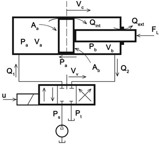
The mathematical modeling describes details of all parts of the HSS. Thus, the nonlinear dynamic effects should be included in the creating of a mathematical model for HSS. The HSS is to consist of a piston, servo valve, hydraulic chamber, and spool valve. Fig. 1 is shown the all part of HSS [5].
Fig. 1Hydraulic servo system
1.2. Equation in the Piston
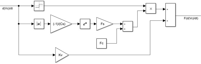
One of the physical drawbacks of the HSS is friction forces that occur in the cylinders of HSS. it can be defined by one experimental function concerning the Stribeck curve [8]. Eq. (1) [1] is illustrated the friction forces in the HSS:
where the viscous friction is , the stribeck friction is , and the Coulomb friction is The represent stribeck velocity range and the is to represent the velocity of the cylinder piston. The simulation for the equation of friction forces is shown in the Fig. 2.
Fig. 2The simulation for equation of friction forces
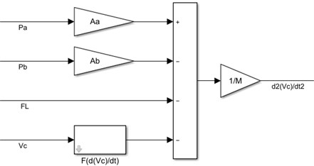
The piston will move due to increase pressure on one of the sides and decrease pressure on another side. The piston movement can be derived based on the second law of Newton to the forces on the piston. It is possible to determine the piston acceleration equation that is related to the piston motion. The piston acceleration load equation is explained below [1]:
where the force of load is . Moreover, the piston mass is . The pressure of oil in the chamber and piston area in the chamber a and b are denoted, , , and . The simulation for the equation of the piston acceleration is shown in Fig. 3.
Fig. 3The simulation for equation of piston acceleration
1.3. Equation in Servo Valve
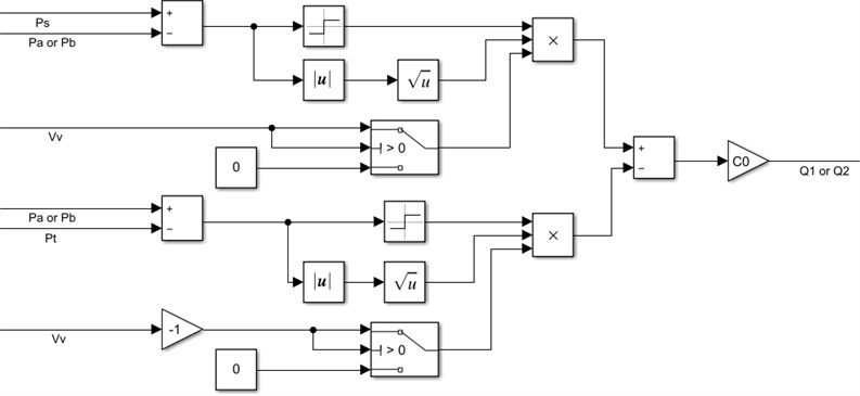
In the HSS, a valve has an important influence on flowing fluid and it may be mechanical or electrical. The classical equation of continuity governs the direction of flow in the servo valve takes into account the direction of the pressure and is being given in Eq. (4) [4]:
The flow equation depends on the change in pressures and the position of the valve piston . If the spool valve considers the four-way with an ideal critical center then it is possible to write the flow equation as in Eq. (5) and Eq. (6) [3]:
where, , , and are a tank compression, working supply pressure Valve, the position of valve piston, and a flow coefficient. The flow equation is shown in Fig. 4.
Fig. 4The simulation for the flow equation
1.4. Equation in hydraulic chambers
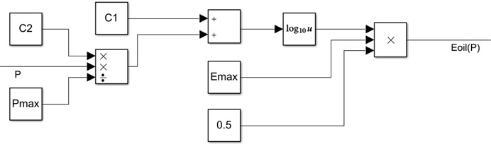
In the HSS, the displacement depends on the force of pressure. One of the terms in the pressure equation is effective bulk modulus for the hydraulic cylinders which can be determined by Eq. (9) [1]:
where is a maximum hydraulic cylinder effective bulk modulus. The and are hydraulic cylinder’s effective bulk modulus coefficients. The is maximum pressure and the is pressure. The simulation of effective bulk is shown in Fig. 5.
Fig. 5The simulation for the effective bulk
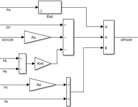
The equation of pressure dynamics in the chamber for differential cylinder depends on the equation of hydraulic capacitance of chamber () and internal chamber leakage flow (). These equations are given below [8]:
where the is internal chamber leakage flow coefficient. The simulation of pressure dynamics in chamber is shown in Fig. 6.
Fig. 6The simulation for pressure dynamics in chamber a
Equations of pressure dynamics in the chamber for the cylinder are the same in pressure dynamics in the chamber but it additionally contains a term of the external leakage flow . These equations are given below [9]:
where the is external chamber leakage flow coefficient. The simulation of pressure dynamics in chamber is shown in the Fig. 7.
1.5. The equation in spool valve
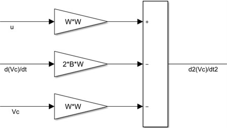
A spool valve is an important part of the HSS that controls the hydraulic fluid flow. The valve consists of spools that rotate or slide to block and open channels in the HSS. The equation of the spool valve is given in Eq. (19) [1]:
where is to represent the natural frequency and it takes a value between 300-500 s-1. B is the damping factor and its value between 0.7-1.0. A spool valve of appropriate modeling includes resetting the integrators by bringing their inputs to zero as soon as the spool valves and positions are surpassed [1]. The simulation for spool valve is shown in Fig. 8.
Fig. 7The simulation for pressure dynamics in chamber b
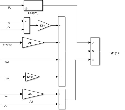
Fig. 8The simulation for spool valve
1.6. Hydraulic servo system (HSS)
The equation in the spool valve, hydraulic chambers, servo valve, and the piston mainly represent behavior in the response of the HSS. Every equation is dependent on another. So, the controller will put on the input of the spool valve that will enhance the response of the HSS. The FOPID will give the appropriate signal to the spool valve to open and close the valve. The simulation of the HSS is shown in Fig. 9.
2. Fractional order proportional integral derivative (FOPID)
The FOPID controller has taken important attention from both an industrial and an academic point of view in the last years. It has a similarity with the conventional PID controller but it is more stable and more complex in the controller design because they have five parameters to select instead of three in the PID controller. The FOPID controller tuning can be even more complex but when the FOPID controller uses to control a system, the response of a system will become more robust compared to the PID controller. The FOPID controller and system are illustrated in Fig. 10. In 1997, Podlubny had proposed the concept of FOPID controllers [10]. The equation of FOPID is illustrated in Eq. (21) [10]:
where and are error signal and controller signal. And , , and are proportional, integral, and derivative gain respectively. and is a power parameter of integral and derivative for the FOPID controller. When the FOPID controller design for any system, the FOPID need five parameters , , , , and . The and should be any real number [11].
Fig. 9The simulation of the HSS
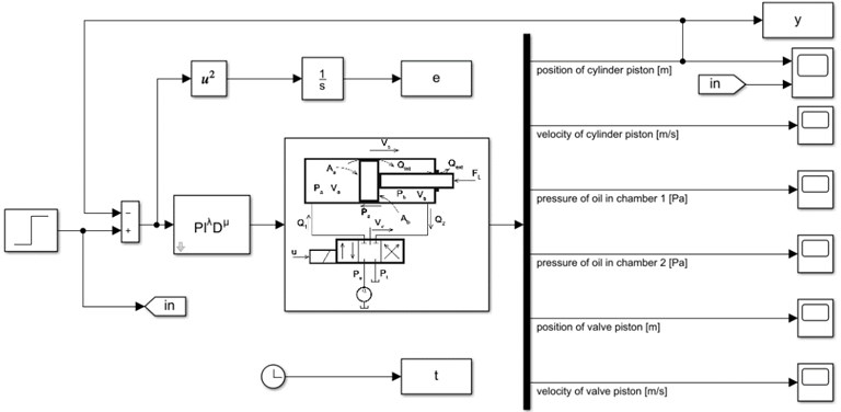
Fig. 10FOPID control and system [7]
![FOPID control and system [7]](https://static-01.extrica.com/articles/21872/21872-img10.jpg)
3. Particle swarm optimization (PSO)
The PSO is a popular algorithm of optimization that finds the best solution for a problem. In 1987, Reynold inspired the simple equations from the behavior of individuals in flying swarms [12]. Separation, alignment, and cohesion are fundamental principles in particle swarm which is illustrated in Fig. 11. It can be shown in this figure that forces to avoid a collision are applied by the separation. In the alignment, the flying path of an individual is changed basing on its neighbors. In cohesion, a certain distance is maintained between the individuals to prevent separation.
Every bird in the swarm has location and velocity where the location represents a solution for probable and velocity is a bird’s speed toward the best solution. The location and velocity of the bird are initialized by random and update by Eq. (16) and Eq. (22) [12]:
where is inertia weight for which is the velocity of a bird at the position . There are the local best bird and global best bird , where the best one in neighbors is the local best bird, while the best one in the neighborhood is the global best bird. and are two values that are denoted cognitive and social learning factors respectively. and are stochastic numbers in the range between 0 and 1.
Fig. 11The fundamental principles in particle swarm [12]
![The fundamental principles in particle swarm [12]](https://static-01.extrica.com/articles/21872/21872-img11.jpg)
a) Separation
![The fundamental principles in particle swarm [12]](https://static-01.extrica.com/articles/21872/21872-img12.jpg)
b) Alignment
![The fundamental principles in particle swarm [12]](https://static-01.extrica.com/articles/21872/21872-img13.jpg)
c) Cohesion
The inertia weight regulates the behavior of convergence in PSO. Originally, the inertia weight was a constant value. However, experimental results showed that it was easier to set the inertia weight to a higher value initially and progressively decrease it to obtain refined solutions. Inertia weight is given as linearly decreasing in Eq. (24) [13]:
where the is the smallest value of the inertia weight and the is the highest value of the inertia weight, the current iteration, the the greatest number of admissible iterations.
The main reason to use the PSO with the FOPID controller is to improve the response of hydraulic actuators. The PSO algorithm will find optimal values for the five parameters of controller , , , , and . Each bird represents the five parameters of controller , , , , and where is [, , , , ], and , , , , and are real numbers. PSO algorithm uses a population of birds called a swarm. Let’s assume be the number of birds. Hence, the size of the swarm is , as shown below in the matrix:
The main objective of the PSO with the FOPID is to find a set of best parameters for controller , , , , and which can improve the output of system response. This set obtains by the fitness function described in Eq. (26) [14]:
where the and the are the settling time and system error of the response of the system. The , , and are a constant value. The coefficient is important for the smooth curve and can be reduced the settling time of the response of the system. The punishment overshoot method (POM) is adopted to prevent the overshoot in the response of the system. The punishment item is added to the fitness function. The is much larger than . The parameters choosing of , , and is very important for optimization results. Our experiment shows that it is very necessary to select and carefully [14].
4. Results
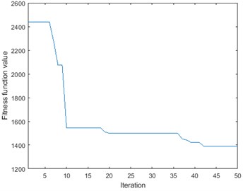
The five parameters of the controller will be given by the PSO. Then the fitness function will be returned to the PSO. The PSO will calculate the global best bird and the local best bird. This behavior of PSO to find the best parameter for the FOPID controller is shown in Fig. 12.
Fig. 12The PSO convergence characteristic in the HSS
The step signal with 0.03 m height is applied to the model of the HSS as the input. The results such as settling time and percentage overshoot are illustrated in Table 1. The simulation results are to show that using the punishment overshoot method gives a better settling time and percentage overshoots in comparison with [9]. This is due to the use of system error and settling time and multiple by weights in the fitness function.
Table 1The results of the simulation model based on the PSO
Method | Settling time (sec) | Overshoot (%) |
IAE in [9] | 1.65 | 1.4 |
ISE in [9] | 1.64 | 1.4 |
ITAE in [9] | 1.7 | 0.71 |
POM | 1.06 | 0.47 |
Fig. 13The time response for the position of cylinder piston
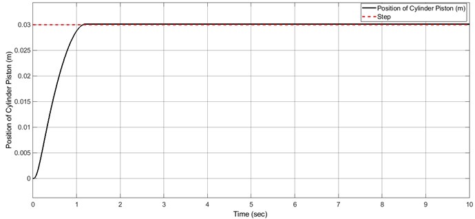
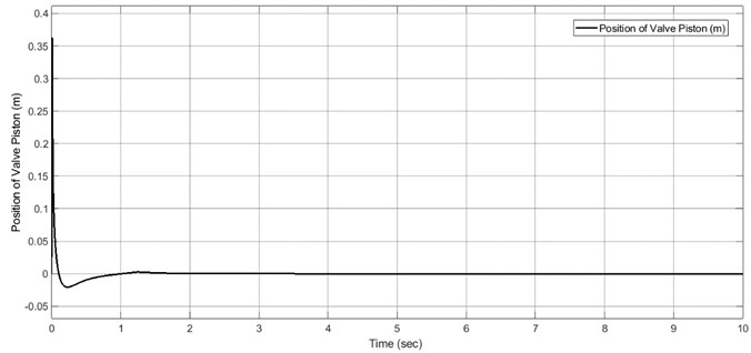
Fig. 14The time response for the position of the valve piston
5. Conclusions
The modeling for the HSS was based on a physical system that had introduced by another researcher but it improved by our proposal. The MATLAB-SIMULINK had used for the simulation for modeling of the HSS. This work takes all parameters and effects for the HSS to get results near to a real physical system. The tuning for parameters of the FOPID controller has been developed based on the PSO. The simulation results show that the superiority of using the FOPID controller in case of minimum settling time and minimum overshoot when it is the comparison with [9].
References
-
Sulc B., Jan J. A. Non linearmodelling and control of hydraulic actuators. Acta Polytechnica, Vol. 42, Issue 3, 2002, https://doi.org/10.14311/354.
-
Salimbahrami Reza S., Shakeri Reza Experimental investigation and comparative machine-learning prediction of compressive strength of recycled aggregate concrete. Soft Computing, Vol. 25, Issue 2, 2021, p. 919-932.
-
Maneetham Dechrit, Afzulpurkar Nitin Modeling, simulation and control of high speed nonlinear hydraulic servo system. Journal of Automation, Mobile Robotics and Intelligent Systems, Vol. 4, Issue 1, 2010, p. 94-103.
-
Goran Gregov, Dubravka Siminiati Computer simulation of a laboratory hydraulic system with Matlab-Simulink. 8th International Scientific Conference on Advanced Engineering, Computer Aided Design and Manufacturing CADAM 2010 Proceedings, 2010.
-
Magdy Aboelela A. S., Mohamed El Sayed Essa M., Mustafa Hassan M. A. Modeling and identification of hydraulic servo systems. International Journal of Modelling and Simulation, Vol. 38, Issue 3, 2018, p. 139-149.
-
Milic Vladimir, Situm Zeljko, Essert Mario Robust H∞ position control synthesis of an electro-hydraulic servo system. ISA Transactions, Vol. 49, Issue 4, 2010, p. 535-542.
-
Tanasak Samakwong, Wudhichai Assawinchaichote PID controller design for electro-hydraulic servo valve system with genetic algorithm. Procedia Computer Science, Vol. 86, 2016, p. 91-94.
-
Dirk Nissing A vibration damped flexible robot: identification and parameter optimization. Proceedings of the American Control Conference, 2000.
-
Mohamed El Sayed Essa M., Magdy Aboelela A. S., Mohammed Hassan A. M. A comparative study between ordinary and fractional order PID controllers for modelling and control of an industrial system based on genetic algorithm. 6th International Conference on Modern Circuits and Systems Technologies, 2017.
-
Mohamed El Sayed Essa M., Magdy As Aboelela, Mohamed Ahmed Moustafa Hassan Position control of hydraulic servo system using proportional-integral-derivative controller tuned by some evolutionary techniques. Journal of Vibration and Control, Vol. 22, Issue 12, 2016, p. 2946-2957.
-
Aboelela Magdy A. S., Hennas Rania Helmy Mansour Development of a fractional-order PID controller using adaptive weighted PSO and genetic algorithms with applications. Fractional Order Systems, 2018, p. 511-551.
-
Mirjalili Seyedali Evolutionary algorithms and neural networks. Studies in Computational Intelligence, Springer, Vol. 780, 2019.
-
Bansal J. C., Singh P. K., Mukesh Saraswat, Abhishek Verma, Shimpi Singh Jadon, Ajith Abraham Inertia weight strategies in particle swarm optimization. 3rd World Congress on Nature and Biologically Inspired Computing, 2011.
-
Li Xu Zhou, Yu Fei, Wang You Bo PSO algorithm based online self-tuning of PID controller. International Conference on Computational Intelligence and Security, 2007.
About this article

