Abstract
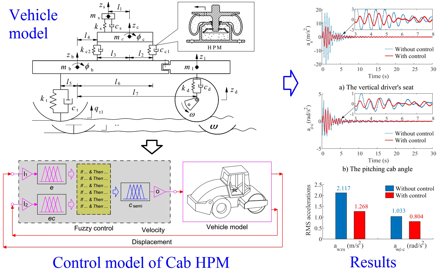
In order to further enhance the ride quality of vibratory roller’s cab used by the hydro-pneumatic mounts (HPM), based on a nonlinear dynamics model of the vibratory rollers under interaction of the deformable terrain and drum established based on Matlab/Simulink software, a semi-active cab’s HPM of vibratory rollers are then controlled by using the Fuzzy controller. The root-mean-square (RMS) of the accelerations of the vertical driver’s seat and the cab’s pitch angle have been used as objective studies. The research results indicate that the ride comfort of the driver's seat and the shaking of the cab are greatly affected under the deformable soil grounds, especially under a soft soil ground. However, with the HPM using the Fuzzy control, the RMS accelerations of the driver’s seat and cab pitch angle have been remarkably decreased by 40.1 % and 22.2 % under a hard soil ground. Therefore, the ride quality of the vibratory roller has been enhanced by the semi-active HPM.
Highlights
- A semi-active cab's HPM of vibratory rollers are then controlled by using the Fuzzy controller further enhance the ride quality of vibratory roller's cab used by the hydro-pneumatic mounts.
- The root-mean-square (RMS) of the accelerations of the vertical driver's seat and the cab's pitch angle have been used as objective studies.
- The research results indicate that the ride comfort of the driver's seat and the shaking of the cab are greatly affected under the deformable soil grounds, especially under a soft soil ground.
- Especially, the RMS accelerations of the driver's seat and cab pitch angle have been remarkably decreased by 40.1 % and 22.2 % under a hard soil ground.
1. Introduction
The vibratory rollers often work in factories and construction site, and its operation process includes a combined static and dynamic forces of all the vehicle and the drum to compress the asphalt, terrain, or other materials. The vibration excitations from the deformable terrain and the drum are thus transmitted the driver via the cab and the vehicle's isolation systems [1-3]. Consequently, in the design process of the vibratory rollers often, the designer always wants the vertical excitations from the drum impacting on the terrain ground to be maximum, and the vibration sources from the vehicle frame transmitted to the cab floor via isolation mounts to be minimum.
Basic research of interaction models of the tyre-soft soil and of the drum-elastoplastic soil showed that the responses the vehicle vibration had been greatly influenced by off-road soil grounds [4-6]. The excitations from off-road terrains and the vibratory drum were almost transmitted to the cab floor via its isolation system and the driver’s drive via its suspension. Consequently, the isolation system of the cab is one of the most important indexes for improving the vehicle's ride quality.
The cab’s isolation system of the vibratory rollers equipped with the hydraulic mounts has been researched and controlled [7-10]. The study results indicated that the ride quality of the vehicle had been greatly improved by semi-active hydraulic mounts. However, the results also showed that vibrations heave of the driver’s seat and the shaking of the cab were still high under various operating conditions. Therefore, to enhance the ride quality of the vehicle and control the shaking of the cab, a combination of the hydraulic and pneumatic mounts for the cab of vibratory rollers was proposed and studies [11, 12]. The combination results between the rubber mounts (RM), hydraulic mounts (HM), and hydro-pneumatic mounts (HPM) in Part 1 showed that the HPM improved the ride comfort of the vibratory roller cab is better than both isolation of the RM and HM. However, the vibrations of the driver’s seat heave and the cab shaking were also still great under various operating conditions. To solve this issue, to control the HPM is necessary. The control method of the Fuzzy control were also applied to control the hydraulic mounts of the soil compactor cab or the vehicle suspension systems [8, 9, 13]. The control results significantly reduced the vehicle vibrations. Thus, the Fuzzy control can be also applied to control the HPM of the vibratory roller cab.
In this research, based on the model of the vibratory roller and deformable terrain interaction, and the dynamics model of the vibratory rollers built under the vibration excitations consisted by the drum/tires-deformable terrain contact in the condition of the vehicle traveling; and of an excitation of the drum 28 Hz in the condition of the vehicle working in an elastic/plastic ground in Part 1. A semi-active hydro-pneumatic mounts (HPM) controlled based on the Fuzzy control to further enhance the ride comfort of the vibratory roller is then researched and applied. The performance of the semi-active HPM is then evaluated via the weighted RMS accelerations of the driver’s seat and the cab’s pitch angle under two working conditions of the hard and soft soil grounds.
2. The dynamics model of vibratory rollers
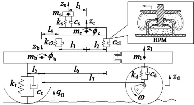
The vibratory roller is mainly composed of the wheel, body, cab, seat, and vibrator drum, among which cab and rear vehicle frame are mainly connected through the cab isolation systems to improve the vehicle’s ride comfort. The vibration system of vibratory roller is composed of vibration mechanism, steel drum, shock absorber, drive plate and vibration frame. The vibration mechanism is the force source of vibration of the vibratory roller, and the centrifugal force generated when the vibratory axis rotates is the vibratory force of the vehicle. Based on the actual vehicle structure, the nonlinear dynamic model of vehicle is modeled as in Fig. 1, where, , , , and are the vertical displacement of the rear frame, front frame, cab, and seat; is the vertical displacement of the flat section of the drum-ground contact surface; , , , and are the weights of the rear frame, front frame, cab, and seat; and are the moment of inertia of the rear frame and the cab; , , and are the stiffness of the vibration isolators of the seat, front and rear cab, respectively; , , and are the damping of the vibration isolators of the seat, front and rear cab, respectively; is excitation of the road roughness; and are the cab and rear frame's pitch angles; , , , , , , and are the geometric dimensions.
Fig. 1The nonlinear dynamics model of vibratory rollers
Based on the vehicle dynamics model, the dynamic differential equation is given by:
3. Semi-active cab hydro-pneumatic mount of the cab
Based on the research results in Part-1, the three types of isolation systems including the rubber mounts (RM), the hydraulic mounts (HM), the hydro-pneumatic mounts (HPM) are compared. The results showed that the HPM is the best on improving the ride comfort. Therefore, to further improve the ride comfort of the vibratory roller, this paper proposes the semi-active HPM controlled by using Fuzzy control to enhance the ride comfort of the vehicle. The model of the semi-active HPM is indicated as in Fig. 2, where, and are the linear stiffness of the HPM, is the main damping coefficient of the HPM mounts, and is the variable damping coefficient. Liquid damping force is expressed by quadratic nonlinear damping characteristics, including on behalf of the coefficient of the hydro-pneumatic damping mounts, is the air’s move in the pipe.
Fig. 2The mathematical model of the passive and semi-active HPM of the cab
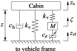
a) Passive HPM
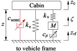
b) Semi-active HPM
The corresponding vertical dynamic forces of the front and rear isolations are given as follows [8, 11]:
where, and are the vertical displacements of suspension of cab and front and rear frames, 1, 2.
4. Application of the Fuzzy control for the HPM
The fuzzy logic controller was incepted by Zadeh in 1965. It is then widely applied in variety situations as well as diverse fields. A fuzzy logic-based control for semi-active suspension of vehicle is suggested and the capabilities for the improvement of ride comfort are studied through the software simulation. In this study, to control the semi-active HPM, the fuzzy control is designed and then applied to control the damping coefficient of the HPM.
The fuzzy logic controller consists of a fuzzification interface, a fuzzy inference system and a defuzzification interface. First, the crisp values in fuzzification are transformed into linguistic variables. The fuzzy inference system is then used by the fuzzy rule in accordance with the inference rule. Finally, the linguistic variables are transformed back to crisp values through defuzzification for use by the physical plant of the air suspension system [13-15]. Herein, the relative displacement z and the relative velocity of the HPM in Fig. 2(b) are considered as two input variables while the damping coefficient is the output of the fuzzy control. The control model is plotted in Fig. 3.
Fig. 3The model of the Fuzzy control for the HPM
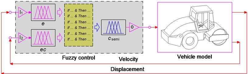
The nine value of the linguistic variables of input/output signals are defined by the positive very big (PVB), positive big (PB), positive medium (PM), positive small (PS), zero (Z), negative small (NS), negative medium (NM), negative big (NB), negative very big (NVB) and ( 1, 2, …, 9).
Fig. 4Membership functions for input and output variables of the PHM
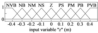
a) The relative displacement
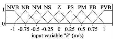
b) The relative velocity
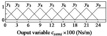
c) The damping coefficient
The membership functions for input and output variables of the semi-active HPM have been represented via a fuzzy set. The shape of membership functions is the triangular function and the value of the degree of memberships is between 0 and 1, as shown in Fig. 4.
In this fuzzy controller, the rules of “if-then” are used to define the relationship of , and according to the designers’ knowledge and experience, the fuzzy controller has all 81 possible rules listed in Table 1.
To calculate the control results of the fuzzy controller, the fuzzy inference system is applied by the minimum function and the centroid method of Mamdani [15, 16]. In this paper, Mamdani’s fuzzy inference system is used to control the semi-active HPM.
Table 1Rules for fuzzy control
NVB | NB | NM | NS | Z | PS | PM | PB | PVB | |
NVB | |||||||||
NB | |||||||||
NM | |||||||||
NS | |||||||||
Z | |||||||||
PS | |||||||||
PM | |||||||||
PB | |||||||||
PVB | |||||||||
5. Simulations and discussions
5.1. Evaluation index
In the vehicle working process, the uneven road surface and rotating parts such as engine, transmission system, and wheels will stimulate the vibration of the vehicles. The vehicle’s ride comfort is mainly to maintain the impact of the vibration and impact environment generated in the driving process on the ride comfort of passengers. Within a certain range, each person's psychological and physical qualities are different, so the sensitivity to vibration is very different. Therefore, the basic evaluation method of the weighted root-mean-square value of acceleration is used to evaluate the impact of vibration on the human's ride comfort and health, as follows [8]:
where, is the weighted acceleration time history recorded by obtained through the simulation process; is the analysis time of vibration.
5.2. Analysis results
To evaluate the performance of the semi-active HPM, based on the lumped parameters of the vibratory roller and cab isolation mounts in Part-1 listed in Tables 2 and 3, a single-drum vibratory roller compacting and moving at the excitation frequency of the drum 28 Hz and 5 km/h on two different grounds of the hard and soft soils is simulated and controlled by using Fuzzy controller. The simulation results of the acceleration responses of the vertical driver and pitching cab angle are plotted in Figs. 5 and 6.
Table 2The lumped parameters of the vibratory rollers
Parameter | Value | Parameter | Value | Parameter | Value | Parameter | Value |
/ kg | 85 | / kgm2 | 1.2×10⁴ | / m | 0.383 | / N m-1 | 1.2×10⁴ |
/ kg | 891 | / kgm2 | 1.9×10³ | / m | 0.1 | / N m-1 | 3.9×10⁶ |
/ kg | 2822 | / kgm2 | 3.0×10³ | / m | 0.524 | / N m-1 | 0.5×10⁶ |
/ kg | 4464 | / m | 0.55 | / m | 0.136 | / Ns m-1 | 1.2×10² |
/ kg | 4378 | / m | 0.7 | / m | 0.76 | / Ns m-1 | 2.9×10³ |
/ kgm2 | 560 | / m | 0.68 | / m | 0.9 | / Ns m-1 | 4.0×10³ |
/ kgm2 | 523 | / m | 0.945 | / m | 0.6 | / Hz | 28 |
/ kgm2 | 3.1×10³ | /m | 0.945 | /m | 1.5 | / km h-1 | 5 |
Table 3The lumped parameters of the cab’s HPM
Parameter | Value | Parameter | Value | Parameter | Value |
/ Nm-1 | 9.1×10⁵ | / Nm-1 | 15.3×10⁵ | / Ns2m-2 | 12.4×10³ |
/ Nm-1 | 1.2×10⁵ | / Nm-1 | 2.01×10⁵ | / Ns2m-2 | 10.7×10³ |
/ kg | 98 | / Nsm-1 | 218 | / Ns2m-2 | 20×103 |
/ Nm-1 | 9.1×10⁵ | / Nsm-1 | 29 | / Ns2m-2 | 4.5×10³ |
/ Nm-1 | 1.2×10⁵ | / kg | 33 |
Fig. 5The acceleration responses under a hard soil
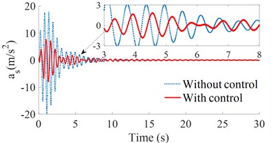
a) The vertical driver’s seat
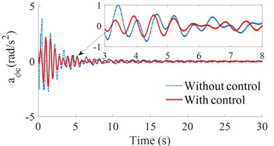
b) The pitching cab angle
Fig. 6The acceleration responses under a soft soil
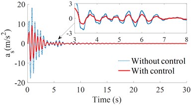
a) The vertical driver’s seat
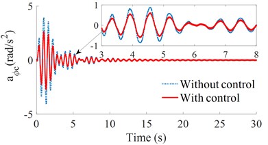
b) The pitching cab angle
By analyzing the images and data in Figs. 5 and 6, it can see that, on the ground of the hard soil, the isolation mounts of the HPM with controlled damping performs better than the uncontrolled isolation mounts, and the values of the crest are also much lower than that of the uncontrolled isolation mounts. Besides, the time to reach the stable fluctuation range is also shorter than that of the uncontrolled HPM, and the advantage of the controlled HPM in the vertical acceleration of the driver's seat is more obvious. On the ground of the soft soil, the controlled damping suspension also has a good control of the vertical driver's seat and cab pitch angle. Therefore, on both the soft or hard soil grounds, the controlled HPM has a better improvement in both the acceleration responses of the vertical driver’s seat and cab pitch angle than the uncontrolled HPM.
Fig. 7The RMS acceleration responses of the cab and driver’s seat
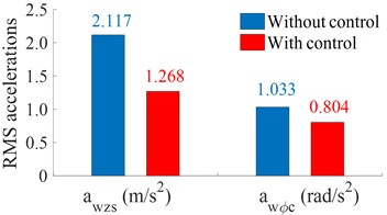
a) Under a hard soil ground
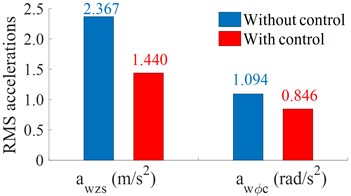
b) Under a soft soil ground
According to the chart and recorded data of the simulation process, the RMS acceleration responses of the cab and driver's seat are also shown in Fig. 7. The comparison results show that the vertical acceleration of the driver's seat with control is greatly reduced by 40.1 % compared to the HPM without control, and the cab pitch angle with control is about 22.2 % less than that of the HPM without control on a hard soil ground. On a soft soil ground, the vertical acceleration of the driver's seat with control is reduced by 39.2 % compared with that without control, and the cab pitch angle with control is lower 22.7 % compared to the HPM without control. This obtained result is due to the damping coefficient of the damper mount is optimized by the Fuzzy control in the vehicle competing and working process. Therefore, the controlled HPM can improve the vehicle’s ride comfort under both the hard and soft soil grounds.
6. Conclusions
The data analysis of the hydro-pneumatic mounts and its semi – active of the vibratory roller cab has obtained the corresponding results through simulation and test. By changing the damping through fuzzy control of the HPM, the RMS accelerations of the vertical driver’s seat and the pitching cab angle under various conditions are obtained to evaluate the ride comfort. These research results are summarized as follows:
1) When the vehicle moving at 5 km/h, whether on the hard or soft soil grounds, the damping coefficient with control has a better improvement the acceleration vibrations in all the vertical driver’s seat and cab pitch angle than the uncontrolled damping coefficients, especially on the hard soil ground.
2) Under the vehicle working condition at 5 km/h and 28 Hz of the vibrator drum, the RMS accelerations of the driver’s seat and cab pitch angle are greatly reduced by 40.1 % and 22.2 % compared to the HPM without control under a hard soil ground, and by 39.2 % and 22.7 % under a soft soil ground. Therefore, the vehicle’s ride comfort is further improved by using the semi-active HPM.
3) The above analysis result shows that the HPM has outstanding performance in various types of isolation mounts in Part-1, and the semi-active HPM used with the Fuzzy control has superior performance compared to the HPM without control.
References
-
Adam D., Kopf F. Theoretical analysis of dynamically loaded soils. Proceedings of European Workshop Compaction of Soils and Granular Materials, Paris, France, 2000, p. 207-220.
-
Le V., Zhang J., et al. Experimental modal analysis and optimal design of cab’s isolation system for a single drum vibratory roller. Vibroengineering Procedia, Vol. 31, 2020, p. 52-56.
-
Nguyen V., Zhang J., et al. Vibration analysis and modeling of an off-road vibratory roller equipped with three different cab’s isolation mounts. Shock and Vibration, Vol. 2018, 2018, p. 8527574.
-
Mitschke M. Dynamik Der Kraftfahrzeuge. Springer-Verlag, Berlin, Germany, 1972.
-
Wong J. Y. Data processing methodology in the characterization of the mechanical properties of terrain. Journal of Terramechanics, Vol. 17, Issue 1, 1980, p. 13-41.
-
Bekker M. Introduction to Terrain-Vehicle Systems. University of Michigan Press, Ann Arbor, Michigan, USA, 1969.
-
Nguyen V., Nguyen K. Enhancing the ride comfort of the off-road vibratory roller cab by adding damper hydraulic mount. Vibroengineering Procedia, Vol. 21, 2018, p. 89-95.
-
Nguyen V. L., Zhang J. R., et al. Low-frequency performance analysis of semi-active cab’s hydraulic mounts of an off-road vibratory roller. Shock and Vibration, Vol. 2019, 2019, p. 8725382.
-
Nguyen V., Zhang J., et al. Performance analysis of semi-active hydraulic system of the off-road vibratory roller cab using optimal fuzzy-PID control. Journal of Central South University, Vol. 35, 2019, p. 399-407.
-
Nguyen V. L., Zhang J. R., et al. Ride quality evaluation of the soil compactor cab supplemented the auxiliary hydraulic mounts via simulation and experiment. Journal of Central South University, Vol. 35, 2019, p. 273-280.
-
Nguyen V., Zhang J., et al. Low-frequency ride comfort of vibratory rollers equipped with cab hydro-pneumatic mounts. Journal of Southeast University, Vol. 36, 2020.
-
Jiao R., Nguyen V., Le V. Ride comfort performance of hydro pneumatic isolation for soil compactors cab in low frequency region, Journal of Vibroengineering, Vol. 22, 2020, p. 1174-1186.
-
Nguyen V. L., Jiao R. Q., Zhang J. R. Control performance of damping and air spring of heavy truck air suspension system with optimal fuzzy control. International Journal of Vehicle Dynamics, Stability, and NVH, Vol. 4, 2020, p. 179-194.
-
Rao M., Prahlad V. A tunable fuzzy logic controller for vehicle-active suspension systems. Fuzzy Sets and Systems, Vol. 85, 1997, p. 11-21.
-
Karray F., Silva C. Soft computing and intelligent systems design: theory, tools, and application. Addison Wesley, New York, 2014.
-
Mamdani E. Advances in the linguistic synthesis of fuzzy controllers. International Journal of Man-Machine Studies, Vol. 8, 1976, p. 669-678.
About this article

This research was supported by Open Fund Project of Hubei Key Laboratory of Intelligent Transportation Technology and Device, Hubei Polytechnic University, China (No. 2020XY105) and Talent Introduction Fund Project of Hubei Polytechnic University (No. 19XJK17R), and Research Project of Hubei Polytechnic University, China (No. 18XJZ05Q).
