Abstract
With the rapid development of automobile industry, electric vehicles are more and more popular. A large part of the excitation comes from the road, so in the early stage of automobile development, we should pay attention to the vibration and noise caused by the road surface. This paper mainly studies how to simulate and optimize the vehicle road noise with the random method, and focuses on the basic principle of the random method and the road noise optimization method. The simulation of road noise with the random method can effectively predict the performance of the full vehicle. Based on the modal energy of vehicle body, the optimization of road noise performance is carried out, which provides effective basis for vehicle research and development.
1. Introduction
The NVH excitation of the full vehicle mainly comes from the external airflow, power-train and road surface. Because of the large excitation of the power-train of the traditional diesel vehicle, part of the external airflow and road surface excitation will be covered up. With the rapid development of automobile industry and the popularization of electric vehicles, the vibration and noise in the vehicle caused by the road excitation has gradually become the main concern of consumers. This paper mainly describes the basic principle of the random method, and how to simulate the vehicle road noise with the random method, and optimize the road noise performance based on the body modal energy.
2. The basic principle of random analysis
There are basically two types of loading conditions typically encountered in noise and vibration work. The first is a deterministic type of load. These loads are do to systematic, periodic, and generally predictable forces. The second type is the random load. Random vibration is vibration that can be described only in a statistical sense. It’s instantaneous magnitude an any time is not known. The probability of it’s magnitude exceeding a certain value is given.
MSC.Nastran performs random response analysis as post-processing to frequency response. Inputs include the output from frequency response analysis as well as user-supplied loading conditions in the form auto-and cross spectral densities. Outputs are response power spectral densities, auto-correlation functions, number of zero crossings with positive slope per unit-time, and the RMS values of response.
There is a system where is the input points, is the output point, and is the transfer function from the input point to the output point.
When the system is subjected to multiple random excitations, the total response of the system is shown below:
Change the above-mentioned formula into matrix form:
Then the conjugate matrix is as follows:
When a matrix is multiplied by its conjugate matrix, it is as follows:
Suppose there is a formula as follow:
Then:
For a four-wheel vehicle, each wheel is excited in six directions, namely , , , , , . Therefore, there are 24 auto-power spectrums and 552 cross-power spectrums in total.
3. Simulation of vehicle road noise based on random method
3.1. Finite element model
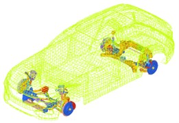
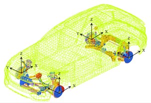
The simulation of vehicle road noise based on random method needs to build a finite element model of vehicle structure and acoustic cavity, in which the finite element model of vehicle structure should include two parts of trimmed body and chassis, as shown in the Fig. 1.
Fig. 1System excited by random signal
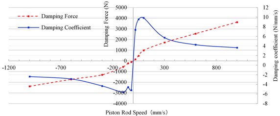
For the equivalent simulation of damper, the damping characteristics varying with frequency should be fully considered.
Fig. 2Dynamic characteristics of damper
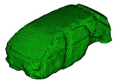
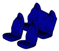
The finite element model of the cavity is built with tetrahedron element, which ensures that the size of the element is 50 mm and the maximum analysis frequency is 680 Hz. The finite element model of the acoustic cavity shall include two parts: passenger compartment and seat, as shown in the figure. Ensuring that 10 elements are distributed in one wavelength.
Fig. 3Acoustic cavity model
3.2. Boundary conditions of road noise analysis
The load acquisition for vehicle road noise simulation adopts the method of combination of test and simulation. Through the test, the acceleration signals of four points that are no coplanar on each steering knuckle are measured, and the vibration transfer function from the wheel core to the test points are analyzed by the simulation method, and then, the loads in six directions at each wheel core are obtained by the inverse matrix method [1, 2].
Fig. 4Loading location
The most important part of the case control is the RANDOM card. The RANDOM card determines which PSD matrix to use for input loads to the system for the random response calculation [3]. This card should be above all sub-case lines.
The DAREA cards have many different options that can lead to confusion. It is strongly suggested that the phase on the DAREA cards be left at zero, and the amplitude left at one. In this case, the output will be the FRF matrix, in modeling units. With this data in the deck, the output of the run will simply be the FRF’s of the system from the input to the output DOF’s. This is the best way to think about a random response run in Nastran.
3.3. Simulation results of road noise
Because the input and output of random analysis are power spectrum [2, 4], so when dealing with the sound pressure response, we should square the output firstly, and then carry on the relevant weight calculation. The road noise of the driver's right ear when the car is traveling on rough road at 60 km/h is shown in Fig. 5. Solid line is simulation value, dotted line is test value.
Fig. 5Road noise
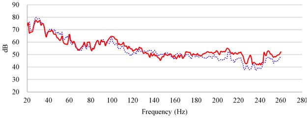
According to comparing with the results of simulation and test, in the frequency band above 180 Hz, the simulation value is higher than the test value, because the effect of floor damping glue on NVH is not considered, so the simulation value is slightly higher than the test value above 180 Hz.
3.4. Improvement of road noise performance based on body modal energy
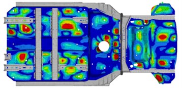
The load from the road surface is transmitted to the car body through the suspension, and part of the energy is gathered in the floor of the body, and coupled with the floor mode to generate vibration, which radiates noise. Therefore, by controlling the vibration of the floor, the noise in the vehicle can be effectively reduced. The effective frequency band of damping glue is above 100 Hz. Therefore, through modal frequency analysis, the floor modes of 100-500 Hz are linearly superposed, and the superposed modal energy of the floor is shown in Fig. 6.
Fig. 6Superposed modal energy of the floor
According to the superposed mode energy, the position and size of the floor damping glue are designed. The blue area indicates the damping glue with a thickness of 2.0 mm, the pink indicates 2.5 mm, and the red indicates 3.0 mm, as shown in Fig. 7.
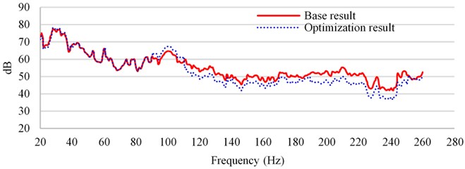
According to the designed floor damping glue, carry out the road noise simulation of the full vehicle again to verify the effectiveness of the scheme. The results are shown in Fig. 8. Through the comparison of the analysis results, it is found that the sound pressure level above 100 Hz is reduced by about 5 dB.
Fig. 7The floor damping glue
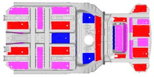
Fig. 8Improvement of road noise performance
4. Conclusions
This paper mainly focuses on the basic principle of the random frequency response analysis, and how to use the random method to simulate the road noise, and the same time, verifies the effectiveness of the road noise performance optimization based on the modal energy. Through the random frequency response analysis, it can effectively predict the road noise performance in the early stage of vehicle development, and provide a reliable basis for design and development. There are three steps to develop vehicle noise caused by road. The first step is to test the road excitation, the second step is to solve the wheel center force load according to the inverse matrix method, and the third step is to simulate and optimize the vehicle road noise.
References
-
Joonhyung Park, Perry Gu, Joe Juan, Archie Ni and James Van Loon Operational spindle load estimation methodology for road NVH applications. SAE 2001-01-1606, 2001.
-
Cho Brian Y. Spindle load application for NVH CAE models by using principal vector approach. SAE 2005-01-1505, 2005.
-
MSC Nastran 2005 R2 Quick Reference Guide, 2005.
-
Park Joonhyung Operational spindle load estimation methodology for road NVH applications. SAE 2001-01-1606, 2001.
About this article

This research was financially supported by two projects that the Key Technology of Acoustic Package Development (011512.07) and the research on Key Technologies of Road Noise Development for Passenger Cars (011907.03).
