Abstract
In view of the phenomenon that the excavator bucket is damaged before it reaches the theoretical life in the actual normal digging process. Based on the continuous trajectory theory, the three-segment continuous trajectory excavated alternately by bucket and rod is selected as the normal digging trajectory. The theoretical digging force (TDF) and limiting digging force (LDF) on the normal digging trajectory are calculated, compared, and analyzed. The influence of bucket structure strength and modal under two different digging force loads on normal excavation trajectory is analyzed. The constrained mode and free mode analysis of the bucket are carried out, and the modal analysis results are compared with the strength analysis results. The results show that on the selected normal digging trajectory, the LDF considering normal force and resistance moment is generally larger than the TDF, and the influence of the LDF load on the bucket structure strength is also larger. The results provide an explanation for the premature damage of the bucket in the process of normal digging.
Highlights
- The normal digging trajectory was selected.
- The structural strength of the bucket was analyzed with the limiting digging force (LDF) as the load.
- The structural strength results are compared with the modal analysis results of the bucket.
- The result provides an explanation for the phenomenon that the bucket is damaged before it reaches the theoretical life in the actual digging process.
1. Introduction
The dynamic characteristics and structural strength of the working device of the excavator have an important influence on the working efficiency of the excavator [1]. Cui [2] takes the whole working device as the research object and analyzes the strength characteristics of the tooling under four typical working conditions. Under the rod digging condition; Huang [3] carries on the modal analysis of the moving arm, obtains the first six natural frequencies and vibration modes of the moving arm, and optimizes the structural strength of the moving arm with the natural frequency as the optimization objective. Zhang [4] compares the static load stress of the tooling stress test with the simulation results, and the finite element model can simulate the static stress characteristics of the tooling under the actual working condition to a certain extent. Zhang [5] based on the theoretical excavation force of the hydraulic cylinder, the static strength analysis and modal analysis of the whole tooling were carried out, and the multi-objective optimization of the working device was carried out by using NSGA-Ⅱalgorithm. The bucket is in direct contact with the material as the executive terminal. When analyzing the structural strength of the bucket, scholars usually take the excavating resistance or the theoretical excavating force (TDF) of the hydraulic cylinder as the load. For example, Sun [6] uses the Drucker-Prager elastic-plastic model to calculate the excavating resistance of the bucket, which is used as the load of the bucket. Xu [7] selected the two working conditions in which the bucket cutting angle was 90° and the bucket cutting radius was parallel to the vertical direction as the premise of bucket strength analysis, and calculated the bucket digging resistance as the load. Yin [8] used the maximum theoretical digging force of the bucket and rod hydraulic cylinder as the load to analyze the bucket strength.
In the process of normal digging, the complex working objects produce random digging resistance, which causes impact and vibration to the excavator bucket, resulting in premature damage to the key parts of the bucket. However, in the previous research on the structural strength of the bucket, only under the ideal condition, on the one hand, the continuous operation trajectory in the normal digging is replaced by the discrete points in the envelope graph, on the other hand, only the tangential resistance is considered. the normal resistance and resistance moment in the real digging process are not considered. That is, when the bucket tooth tip is at a certain digging point, the structural strength of the bucket is evaluated, and the influence of normal digging trajectory and limiting digging force (LDF) on the dynamic characteristics of bucket strength is not considered.
In view of this, a method for analyzing the dynamic strength characteristics of bucket structure based on normal continuous digging trajectory is proposed in this paper, and the LDF model considering normal resistance and resistance moment is used to calculate the load on the continuous digging trajectory. the structural strength analysis results under the action of the TDF and LDF are compared and analyzed. The constrained mode and free mode of the bucket are analyzed and compared with the results of strength analysis.
2. Continuous trajectory theory and normal digging trajectory
In the actual digging process, we will face the operation object of different hardness, in which the bucket and rod hydraulic cylinder play different roles. When the hardness of the operation object is high, because the cutting thickness is reduced, in order to fill the bucket, use the rod hydraulic cylinder for digging, therefore, the digging of different hydraulic cylinders must be fully considered when selecting the digging trajectory. The actual digging process is a continuous digging trajectory, whether it is bucket hydraulic cylinder digging or rod hydraulic cylinder digging, on the premise of avoiding friction between the front wall of the bucket and the working object, the digging action closely related to the working performance of the excavator is determined by the relative angle between the rod and bucket. Different angles can make the working device in different positions, and different digging trajectories can be obtained by changing the angle.
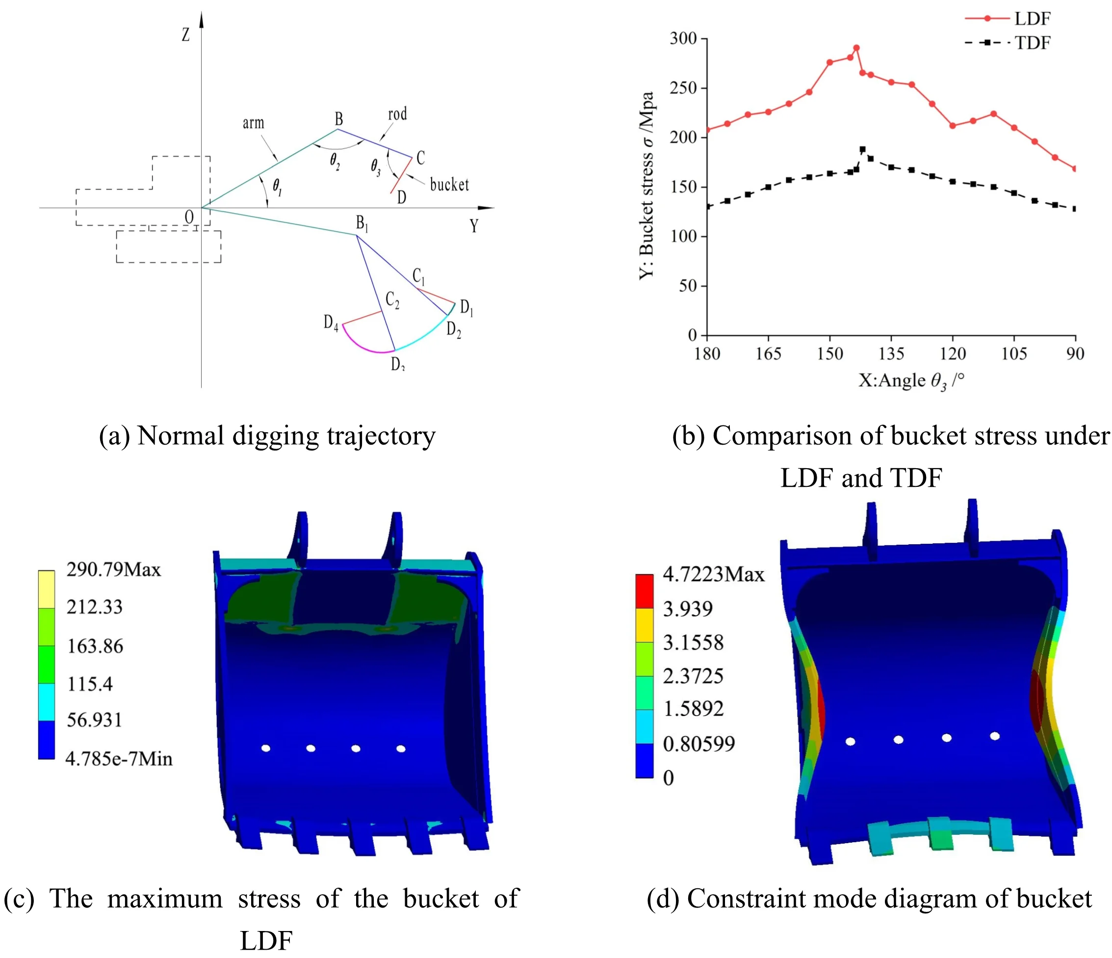
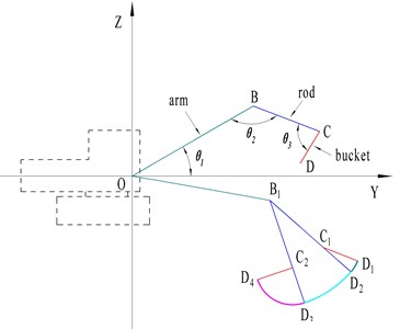
The main digging area of the excavator is below the ground, and the influence of the main digging area on the digging performance is considered at the beginning of the excavator design. Therefore, the digging trajectory in the main digging area is selected as the research premise. The method of selecting the digging trajectory is as follows [9]: first, the digging trajectory is composed of three digging trajectories divided into four feature points (1, 2, 3, 4). The starting point and the ending point of the digging trajectory can be defined separately according to the needs of the designer in the design process, and each other feature point is calculated by changing the angle between the tooling mechanism. Then, in the whole main digging area, by changing the angle between the arm and the horizontal plane , similar multiple digging trajectories can be obtained, and each digging trajectory is composed of three digging trajectories. Finally, several points are selected on the selected digging trajectory to count the working performance of the excavator, including the LDF and TDF of the rod hydraulic cylinder and the bucket hydraulic cylinder on each trajectory. The selected normal digging trajectory is shown in Fig. 1.
In Fig. 1: is the starting point of the trajectory, that is, the angle between the rod and the bucket is in the starting position, the angle between the arm and the horizontal plane is –10°, is the end point of the first section of the trajectory, the initial angle is unchanged, the bucket hydraulic cylinder protrudes, the bucket begins to wedge into the soil, and the bucket angle changes from 219.7° to 180°. The bucket rotates so that the bucket tooth tip , bucket and rod hinge point , rod and arm hinge point are in the same straight line. is the end point of the rod digging of the first section of the trajectory, the bucket angle at point remains unchanged, the rod hydraulic cylinder protrudes, the bucket begins to cut the soil, the angle between the rod and the arm changes from 148.6° to 118.6°, and the bucket tooth tip moves from to . is the end point of the bucket digging in the second section of the trajectory, the angle between the rod at point remains unchanged, the bucket hydraulic cylinder extends again, the soil in the bucket is raised to the specified position, and the angle of the bucket is changed from 180° to 90°. The bucket tooth tip moves from to . In summary, the normal digging trajectory is obtained, which is composed of , and segment trajectories.
Fig. 1Normal digging trajectory
3. Normal digging trajectory load
In the previous research on the dynamic characteristics of the working device, usually only the TDF is taken as the external load, the dynamic characteristics of the tooling are analyzed, and the influence of other factors on the working device is not considered. For the bucket, as the executive terminal where the working device is in contact with the working object, sometimes the bucket is damaged when the theoretical life is not reached, which indicates that the results obtained only under the condition of TDF are not accurate. It is necessary to consider whether the bucket is damaged before reaching the theoretical life because of the existence of a force greater than the TDF. Therefore, this paper takes the TDF and the LDF as the external load of the bucket, compares and studies the influence of the two kinds of digging force on the bucket structure strength, and verifies whether the LDF is the cause of bucket damage.
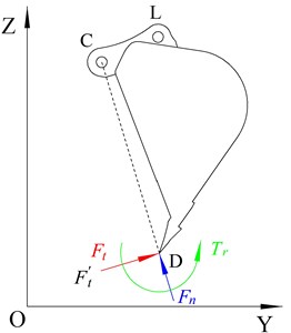
The TDF is the maximum digging capacity of the excavator under specific working conditions. The TDF of a certain digging posture is used to replace the digging force of the excavation point. The TDF obtained is generally less than the actual TDF of the corresponding digging point [10]. Moreover, in the TDF calculation model, only the tangential force and the normal force are considered, and it is considered that the normal force is much less than the tangential force , and the influence of the normal force on the bucket can be ignored in the process of digging, that is, the bucket is only affected by the tangential force , as shown in Fig. 2. In the test, it is found that the calculated TDF is quite different from the actual digging force, which cannot represent the real digging force that the hydraulic excavator can exert. Therefore, scholars put forward the calculation model of LDF [11].
The LDF calculation model holds that in the actual digging process, the bucket bears a complex force system that changes at any time, and when the lateral force is not taken into account, the complex force system can be regarded as a plane force system because of the symmetry of the excavator. It is synthesized into the tangential force , the normal force and the resistance moment , acting on the point in the middle position of the bucket cutting edge, as shown in Fig. 2. Taking the tangential force as a reference, make the resistance coefficient , resistance moment coefficient , where the range of resistance coefficient is –0.4-0.5 and the range of resistance moment coefficient is –0.4-0.2. Different digging trajectories correspond to different tooling angles, and different angles correspond to different resistance coefficient ε and resistance moment coefficient , that is, different tooling posture corresponds to different tangential force , normal force and resistance moment . The normal force and resistance moment in the calculation model of LDF are ignored by TDF, so the LDF is closer to the real situation than TDF.
Fig. 2Bucket load
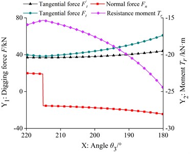
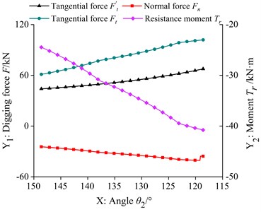
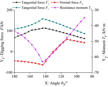
According to the TDF calculation model and the LDF calculation model, two kinds of digging force in each trajectory are calculated respectively, as shown in Fig. 3.
Fig. 3TDF and LDF
a) trajectory
b) trajectory
c) trajectory
As can be seen from Fig. 3(a), in the trajectory, with the decrease of , the tangential force of the TDF of the bucket hydraulic cylinder increases, and the curves of tangential force, normal force and resistance moment of the LDF are almost the same, which decreases at first and then increases with the decrease of . As can be seen from Fig. 3(b), in the trajectory, the tangential force of the TDF and the tangential force and resistance moment curve of the LDF are almost the same, increasing with the decrease of , and the normal force of the LDF increases at first and then decreases. As can be seen from Fig. 3(c), in the trajectory, the tangential force of the TDF and the tangential force and resistance moment curve of the LDF are almost the same, and first increase and then decrease with the decrease of . The angle corresponding to the maximum tangential force of the two kinds of digging force is different, and the normal force curve of the LDF is near zero, showing an irregular up and down fluctuation state. As shown in Table 1, it is the calculation result of the maximum tangential force and the maximum LDF of the theoretical digging force in each section of the trajectory.
Table 1Calculation results of digging force
Trajectory | TDF tangential force / kN | LDF | ||
Tangential force / kN | Normal force / kN | Resistance moment / kN∙m | ||
44.035 | 61.172 | –24.469 | –24.469 | |
67.640 | 101.932 | –35.676 | –40.773 | |
114.37 | 158.458 | –63.383 | –63.383 | |
It can be seen from Table 1 that the tangential force of LDF is about 1.5 times of the tangential force of the theoretical digging force, and the tangential force of LDF corresponding to each trajectory is greater than the tangential force of the theoretical digging force. Comparing the differences of the factors to be considered in the two excavating force calculation models, we can see that the LDF is closer to the real excavating force than the TDF, and the normal force and resistance moment which are not considered in the TDF calculation model may be the important reasons for the damage of the key parts of the bucket.
4. Structural strength analysis under different loads
The three-dimensional solid model of bucket is created by modeling software, and the bucket model is meshed by solid186 element. The number of elements is 226572 and the number of nodes is 419837. A full constraint is imposed on the hinge point C between the bucket and the rod. When the load is applied to the bucket, the maximum tangential force of TDF and the maximum LDF of each trajectory are taken as the external load. In order to prevent excessive calculation error caused by stress concentration, the concentrated force is transformed into a component force distributed in multiple nodes and loaded on multiple nodes [12].
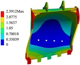
Fig. 4Strength calculation results of LDF
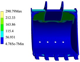
a) Stress
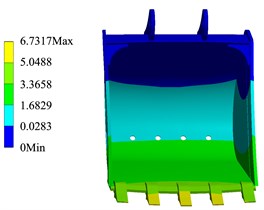
b) Deformation
Through the simulation calculation, the cloud diagram of the bucket structure strength change corresponding to TDF and LDF in each trajectory can be obtained. As shown in Fig. 4 and Fig. 5, when the external load is the LDF and TDF respectively, the calculation results of the bucket structure strength in the trajectory.
Fig. 5Strength calculation results of TDF
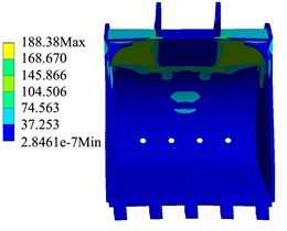
a) Stress
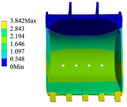
b) Deformation
The simulation results show that when the external load of the bucket is the TDF and the LDF respectively, the stress and deformation of the bucket appear in the same position. It can be seen from Fig. 4 that the larger stress part of the bucket is the welding place of the back plate, the ear plate and the rear wall plate of the bucket, the maximum stress of the bucket in the trajectory is 290.79 MPa, the position of bucket deformation appears in the middle bucket teeth, and the maximum deformation of the bucket in the trajectory is 6.732 mm. As shown in Fig. 6, the stress change of the bucket in the trajectory when the external load is the TDF and the LDF respectively.
Fig. 6Comparison of bucket stress under LDF and TDF
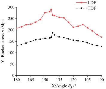
It can be seen from Fig. 6 that the change of normal force and resistance moment in the LDF will have a certain influence on the bucket stress, but the influence of the LDF tangential force on the bucket stress is greater than that of the normal force and resistance moment. At the same time, it can be seen from Section 2 that the tangential force of the LDF is greater than the tangential force of the TDF, so as shown in Fig. 6, the stress of the limit digging bucket is greater than that of the theoretical digging bucket.
The simulation results show that in the whole digging trajectory, when the LDF is taken as the external load, the bucket stress of the point is the highest, and the maximum stress of the bucket is 290.79 MPa, when the LDF is used as the external load. And when the TDF is taken as the external load, the bucket stress is the highest, and the maximum stress of the bucket is 188.38 MPa. The calculation results of bucket structure strength are shown in Table 2.
To sum up, taking the LDF as the external load, the influence on the bucket structure strength is obviously greater than TDF, and the LDF in the trajectory is larger than that in the and trajectories, so the stress and deformation of the bucket in the trajectory are obviously larger than those in the and trajectories. In summary, comparing the differences between the two digging force calculation models, we can see that the normal force and resistance moment in the LDF calculation model is one of the important reasons for the damage of the key parts of the bucket.
Table 2Calculation results of bucket structure strength
Trajectory | TDF | LDF | ||
Stress / MPa | Deformation / mm | Stress / MPa | Deformation / mm | |
84.62 | 1.479 | 149.67 | 4.545 | |
129.18 | 2.272 | 219.47 | 5.715 | |
188.38 | 3.842 | 290.79 | 6.732 | |
5. Modal analysis
In the excavation work of hydraulic excavator, because of the more complex working environment and working object, the bucket often bears strong impact and vibration. When the working frequency of the excavator is close to the natural frequency of the bucket, it will cause resonance and aggravate the vibration of the bucket, thus affecting the working efficiency of the bucket.
Modal analysis is an important method to evaluate the dynamic characteristics of excavator working device [13]. The constraint mode is the inherent vibration characteristic of the bucket under the constrained boundary [14], and the influence of the actual excavation process on the bucket should be considered. According to the constraint method described in Section 3, the constraint on the hinge point of the bucket is imposed, and the constraint modal analysis of the bucket is carried out. The free mode is the inherent attribute of the free vibration of the bucket, which is only related to the bucket structure itself and has nothing to do with the external excitation [15]. Therefore, it is necessary to carry out modal analysis of the bucket without constraint. Through the comparative analysis of the free mode and constraint mode of the 21T excavator bucket, the natural frequency and vibration mode of the bucket are solved, so as to effectively avoid the working frequency being close to the natural frequency of the working device. As shown in Fig. 7, there are the sixth order vibration patterns of the bucket in the constrained mode and the free mod.
Fig. 7Bucket mode diagram
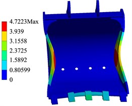
a) Constraint mode
b) Free mode
As shown in Table 3, the natural frequencies and deformations of the first six stages of the bucket in the constrained mode.
It can be seen from Table 3 that the vibration strain of the bucket constraint mode is mainly bending, which is mainly caused by the bending of bucket teeth, side plates, cutting edges and so on. In the first six stages modes, the maximum deformation of each order varies irregularly with the increase of natural frequency. The maximum deformation occurs in the sixth mode, and the maximum deformation is 4.722 mm. As shown in Table 4, the natural frequencies and deformations of the first six stages of the bucket in the bucket in free mode.
Table 3Frequency and deformation of constrained mode bucket
Modal order | 1 | 2 | 3 | 4 | 5 | 6 |
Natural frequency / Hz | 16.124 | 31.210 | 58.774 | 74.189 | 95.507 | 119.717 |
Maximum deformation / mm | 2.544 | 2.435 | 3.436 | 2.336 | 2.042 | 4.722 |
Minimum deformation / mm | 0.00018 | 0.00797 | 0.02178 | 0.00504 | 0.00189 | 0.02273 |
Vibration mode | Bending at the weld of bucket tooth, cutting edge and side plate | Buckle tooth bending | Cutting edge and side plate bending | Bending of bucket teeth and side plates on both sides | Bending of side plate and ear plate | Side plate bending |
Table 4Frequency and deformation of free mode bucket
Modal order | 1 | 2 | 3 | 4 | 5 | 6 |
Natural frequency / Hz | 0 | 0 | 0 | 0 | 1.432e-4 | 48.448 |
Maximum deformation / mm | 1.840 | 2.101 | 1.709 | 2.430 | 2.445 | 2.591 |
Minimum deformation / mm | 0.08093 | 0.09912 | 0.86461 | 0.08041 | 0.12882 | 0.00060 |
Vibration mode | The ear plate and the posterior wall plate of the bucket are bent | Bending of ear plate and back plate | The side plate is bent at the welding joint of the rear wall plate and the back plate of the bucket | Buckle tooth bending | Buckle tooth bending | Bending at the weld of bucket tooth, side plate and back plate |
It can be seen from Table 4 that the natural frequencies of the free mode of first four stages are 0 Hz, showing a rigid body mode, the fifth natural frequency is 1.432e-4 Hz, the vibration mode is mainly bucket tooth bending, and the sixth natural frequency is 44.448 Hz, the vibration mode is mainly bucket tooth bending, side plate and backplane welding bending.
Compared with the constrained mode shape of the bucket, the vibration strain of the free mode of the bucket also shows bending, and in the first four modes, the variation of the strain is irregular; in the fifth and sixth modes, with the increase of natural frequency, the maximum deformation of the bucket is also increasing. The maximum deformation occurs in the sixth mode, and the maximum deformation is 2.591 mm.
To sum up, in the structural strength analysis of the bucket, the stress concentration position of the bucket is the welding of the back wall plate, the back plate and the ear plate, and the larger deformation part is the middle bucket tooth. In the modal analysis, the most frequent distortion phenomenon in the bucket vibration mode is the bucket tooth, which is the same as the structural strength analysis result. therefore, the back wall plate and the back plate, the welding place of the ear plate and the middle bucket tooth are dangerous parts, and the structure can be optimized. reduce the probability of bucket damage.
6. Conclusions
In this paper, aiming at the problem that the bucket is damaged before it reaches the theoretical life, a normal digging trajectory is selected according to the actual digging process of the excavator and the continuous trajectory theory. the changes of two different digging force loads in the normal digging trajectory are compared and analyzed, and the structural strength of the bucket is analyzed by taking the LDF as the external load. The results show that the LDF considering normal force and resistance moment is closer to the real excavating force that the excavator can exert than the TDF. The stress and deformation of the bucket loaded by the LDF is generally larger than that of the TDF, that is, the LDF is one of the important reasons for the damage of the bucket before reaching the theoretical life. The larger deformation part of the bucket mode shape is basically consistent with the larger stress and deformation part of the bucket when the LDF is used as the load. It is proved from the side that the ultimate excavation force will have a certain influence on the structural strength of the bucket. This study provides a certain theoretical basis for the premature damage of the bucket in the process of normal digging, and provides a certain reference for the structure optimization of the working device of the excavator.
References
-
Du W. J., Cui G. H., Liu X. G. Integration finite element analysis on whole working equipment of hydraulic excavator. Transactions of the Chinese Society for Agricultural Machinery, Vol. 10, 2007, p. 20-23.
-
Cui G. H., Zhang Y. W, Zhang Y. S. Strength analysis method for integrated working mechanism of earth-machinery. Transactions of the CSAE, Vol. 24, Issue 1, 2008, p. 157-161.
-
Huang J., Lin S. W., Lin H. Prediction model of boom natural frequency based on modal analysis. Machine Building and Automation, Vol. 48, Issue 4, 2019, p. 100-102+115.
-
Zhang Y. X., Zhao G., Zhang X., et al. Finite element analysis for the hydraulic excavator working device. Modern Manufacturing Engineering, Vol. 2, 2016, p. 89-93+98.
-
Zhang X. M., Li X. L., Wang Y. G. Multi-objective optimization design of backhoe hydraulic excavator working device based on response surface methodology. Journal of Mechanical Strength, Vol. 41, Issue 3, 2019, p. 659-665.
-
Sun J. F., Liu Z. Strength simulation of one hydraulic excavator based on LS-DYNA. Equipment Manufacturing Technology, Vol. 1, 2012, p. 14-15.
-
Xu L. J., Yan S. Z., Li X. Q. Modeling optimization design of excavator bucket based on equal strength mechanics analysis. Journal of Machine Design, Vol. 33, Issue 10, 2016, p. 105-108.
-
Yin S. F., Yin K. Q. Analysis and optimum design of excavator bucket based on SolidWorks. Mechanical Research and Application, Vol. 29, Issue 2, 2016, p. 141-143.
-
Chen J., Qing F., Pang X. P. Optimal design of backhoe hydraulic excavator working device based on synthesis digging. Journal of Zhejiang University (Engineering Science), Vol. 48, Issue 9, 2014, p. 1654-1660.
-
Chen J., Ren Z. G., Pang X. P., et al. Novel digging force calculation method for hydraulic excavator. Journal of Tongji University (Natural Science), Vol. 42, Issue 4, 2014, p. 596-603.
-
Ren Z. G., Wang J. L., Zou Z. H., et al. Modeling of the limiting digging force of hydraulic excavator based on resistance characteristics. Mechanika, Vol. 25, Issue 5, 2019, p. 357-362.
-
Zou W. Strength analysis on propel gearbox of hydraulic excavator. Journal of Mechanical Transmission, Vol. 43, Issue 5, 2019, p. 126-129.
-
Xiao C. Y., Zhang G. J. Modal Analysis on working equipment of hydraulic excavator. The Open Mechanical Engineering Journal, Vol. 9, Issue 1, 2015, p. 173-180.
-
Wang X. B., Tong S. G. Nonlinear dynamics behavior analysis on rigid-flexible coupling mechanical arm of hydraulic excavator. Journal of Vibration and Shock, Vol. 33, Issue 1, 2014, p. 63-70.
-
Li F. Z., Tong S. G., Wang X. B. Dynamic optimization design for working device of hydraulic excavator based on modal analysis. Transactions of the Chinese Society for Agricultural Machinery, Vol. 45, Issue 4, 2014, p. 28-36.
About this article

This research is also funded by National Natural Science Foundation of China (No. 51605270), the Natural Science Research Project of Shaanxi Province (No. 2019JQ-884) and the Shaanxi Provincial Department of Education Scientific Re-search Project (No. 17JK0149).
