Abstract
The present paper discusses impedance and mobility approach integrated with finite element method (FEM) for free vibration analysis of structural-acoustic coupled systems for irregular geometry. In this method, coupled natural frequencies of any irregular geometry with flexible surfaces with different boundary conditions can be estimated. The proposed hybrid method helps to understand the underlying physics of structural-acoustic coupling in complex geometries. The formulation being in impedance and mobility form, gives more insight in understanding coupled modes of the complex geometries. It is for three dimensional irregular geometries, so it can be used in most of the practical applications where coupled natural frequencies play a vital role. The proposed method is demonstrated for regular and irregular geometry with one wall flexible configuration. The results are corroborated with existing literature data for regular geometry and numerical models for irregular geometry.
1. Introduction
Coupled natural frequencies of thin shell structure with fluid medium is an important topic to understand the structural-acoustic coupling in dynamical systems. In 1961, Warburton studied vibration of an infinitely long thin cylinder shell, surrounded by fluid [1]. When fluid is air, system’s resonant frequencies are close to either natural frequencies of uncoupled structural model (structure in vacuum) or uncoupled acoustic model (air with rigid boundary Condition). Dowell developed the theoretical framework further and he formulated the coupled equation of motion in terms of mass, stiffness and damping matrices includes characteristics of flexible wall and acoustic medium [2]. S. M. Kim and M. J. Brennan reformulated the Dowell’s work in the form of acoustic impedance and structural mobility [3, 4]. They have used compact matrix formulation and lumped parameter model. Here, coupled system is divided into several individual linear sub-systems. Each sub-system is characterized by its impedance and mobility. The acoustic and structural interface is expressed in terms of coupling coefficient. G Webster is the first one who applied and found that impedance and mobility representation is useful in structural dynamics and acoustics too [5]. A. Bloch explained the electromechanical analogies and its usage in analysis of electrical and mechanical system [6]. P. Gardonio and M. J. Brennan written a review paper where origin and development of Impedance-Mobility method for structural dynamics is explained [7]. B. Venkatesham extended Kim and Brennan work further and applied the compact matrix formulation to evaluate breakout noise from rectangular duct. Acoustic pressure field inside the duct and normal wall vibrations of flexible surface has been found using analytical formulation and these results are validated using numerical model [8]. Mohamed followed the same methodology to study the structural-acoustic coupling in car tire resonance and compared the results with FEM [9]. Over a last few decades significant development is done in the FEM of the structural-acoustic coupled problem [10]. Several commercial finite element (FE) packages are available to solve structural-acoustic coupled systems [11], however these are computational expenses and hence research is going on to optimize the same. It is very clear that impedance-mobility approach has ease in applications and computational inexpensive as compared to FEM numerical simulations [13]. However, it has some challenges choosing natural frequencies and mode shapes of uncoupled subsystems of complex and irregular geometries. K. S. Sum and J. Pan studied the effects of the inclination of a rigid wall on the free vibration characteristics of acoustic modes in a trapezoidal cavity, and found that for small inclinations, each trapezoidal cavity mode possesses the distorted shape of the rectangular cavity mode that evolves it. When the inclination is increased, the trapezoidal cavity-mode shape becomes complicated and unrecognizable [14]. Dongyan Shi et al proposed a method for the analysis of acoustic modals and steady-state responses of arbitrary triangular prism and quadrangular prism acoustic cavities based on the three-dimensional improved Fourier series [15].
In this paper, hybrid methodology has been developed to study the structural-acoustic coupled problem using the principles of impedance–mobility approach and FE methods. The major contribution in the proposed method is integrating the two methods and deriving equation of motion of structural-acoustic coupled systems. These equations are expressed in terms of modal vectors and natural frequencies which are obtained from uncoupled structural and uncoupled acoustic FE models. These equations are then transformed into standard Eigen value problem to solve for coupled natural frequencies. The transfer factor is then calculated to find the mode coupling strength between acoustic and structural modes. The proposed formulation is for three dimensional irregular cavities, so it can be used in most of the practical applications like off-high way cabins, buildings and automobiles where coupled natural frequencies play a vital role in improving the comfort of the passengers or occupants.
2. Theoretical formulation
Structural-acoustic interaction is a dynamic coupling between acoustic pressure field and structural flexibility. Especially in air and thin shell structure, system response can be expressed in terms of uncoupled sub-systems. In order to address the problem, first it is necessary to formulate the two interacting system independently. For the current coupled problem, it is assumed that strong coupling exists between inside acoustic medium and flexible structure, and weak coupling between outside acoustic medium and flexible structure.
2.1. Impedance-mobility approach
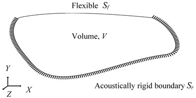
In this section, the impedance and mobility approach is described to predict the coupled natural frequencies of arbitrary shaped volume. It is assumed that coupled natural frequencies of the volume can be described by finite sets of uncoupled acoustic and structural modes. Fig. 1, shows a general schematic diagram of Structural-Acoustic coupled system with inside acoustic volume and flexible structural surface () and acoustically rigid surface () such that surface of the system () is a combination of rigid and flexible surfaces (. Acoustic pressure gradient is zero on the rigid surface and non-zero on the flexible surface.
Fig. 1Structural-acoustic coupled system with inside acoustic volume V and flexible structural surface Sf and rigid surface Sr and total surface area S=Sf∪Sr
Acoustic pressure at some location inside the volume and the wall vibration velocity , at some location on flexible surface can be expressed in terms of finite acoustic modes and structural modes and are given as:
where is the uncoupled acoustic mode shape function and is the complex amplitude of the th acoustic pressure mode. is the uncoupled vibration mode shape function and is the complex amplitude of the th structural mode. uncoupled acoustic modes and uncoupled structural modes can give rise to linear algebraic equations. These equations are rearranged in the matrix form to develop a standard eigen value problem which can be solved for coupled natural frequencies of the system [8]. Same has been elaborated below, first by expressing the in generalized form followed by similar expressions for [3]:
where, and are fluid density and velocity of sound respectively. is acoustic modal mass:
represents the acoustic source strength density function. Here, it is zero for free vibration analysis (no excitation). is acoustic mode resonance term and it is given as:
where and are acoustic natural frequency and damping ratio of th acoustic mode, respectively. Substituting Eqs. (4- 5) into Eq. (3) for free vibration analysis gives:
where is known as coupling coefficient which represents the spatial match (geometric coupling relation) between th uncoupled acoustic and th uncoupled structural mode shapes over the flexible surface :
Complex amplitude of all acoustic modes, represented by can be expressed in terms of finite integration of impedances of each th acoustic mode:
is also defined as modal acoustic pressure vector of size (). is coupling coefficient matrix of size (). is uncoupled acoustic modal impedance diagonal matrix of size () and it is given as:
The matrix () is a diagonal matrix consisting of as diagonal terms. Similarly, complex amplitude of th uncoupled structural mode is given as:
where is structural modal mass which can be expressed in terms of normalized modal vector, density () and are structural density and thickness of the structure:
where represents the force distribution function over surface . Since direction of the force and generated acoustic pressure are in opposite direction, hence negative sign is present inside the bracket. The structural mode resonance term is given as:
where and are uncoupled structural natural frequency and damping ratio of th structural mode, respectively. Substituting Eqs. (11-12) into Eq. (10) for free vibration analysis gives:
where, . Complex amplitude of all structural modes, represented by can be expressed in terms of finite integration of mobilities of each th structural mode:
where is also defined as modal structural velocity of vector of size (). is transpose of the coupling coefficient matrix and its size is (). is uncoupled structural modal mobility diagonal matrix of size () and it is given as:
The matrix () is a diagonal matrix consisting of as diagonal terms. Substituting in the Eq. (6) and rearranging the terms:
Substituting in the Eq. (13) and rearranging the terms:
Now rearranging Eq. (17) and Eq. (19) in a matrix form to establish coupled equation of motion and rearranging the terms:
Eq. (20) can be expressed in generalized form:
where, , and are mass, coupling and stiffness matrices, respectively. is vector comprises of mode resonance terms . By means of matrix transformation, non-standard eigen value problem can be expressed in term of standard eigen value problem by substituting :
Above equation is solved for system’s coupled natural frequencies. Transfer factor which identifies the well coupled modes for structural-Acoustic coupled system is stated as [16]:
It consist of coupling coefficient and structural modal matrices. means weak coupling and , means strong coupling between acoustic and structural modes.
3. A hybrid methodology for coupled problem
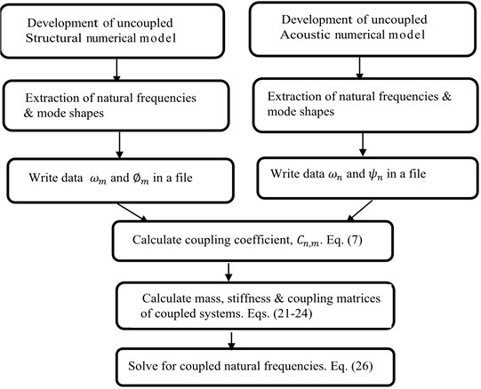
Impedance and mobility approach discussed in Section 2 can be used to predict the coupled natural frequencies of the arbitrary volume provided uncoupled structural and acoustic modes are known. In general, for irregular shaped volumes uncoupled structural and acoustic modes cannot be estimated by analytical approach. Numerical methods like finite element method are used for predicting the coupled modes of irregular shaped volumes. In this section, hybrid methodology for coupled problem is proposed as an alternative which can give more insight in to the prediction of coupled natural frequencies. Fig. 2, shows the flow chart for the hybrid methodology for structural-acoustic coupled systems. The first step of the method involves developing an individual FE models to extract the natural frequencies and modal vectors of the uncoupled structure and acoustic models. Any FE package with eigen solver that supports both structural and acoustic analysis can be used. Next step involves writing of the relative nodal displacements and modal frequencies corresponding to each acoustic and structural modes on a data file using the FE package. These data files are then used as input for the further matrix analysis using any mathematical computational software. The last step is solving the matrices to give system coupled natural frequencies, coupling coefficient and Transfer factor. However, the same equations can be used to find impedance and mobility of the systems.
Fig. 2Flow chart of hybrid methodology for calculating coupled natural frequencies
3.1. Validation of hybrid impedance and mobility methodology
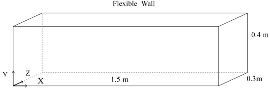
A rectangular duct with one wall flexible as shown in Fig. 3, is considered for validation study. The dimensions of the duct are 0.3 m × 0.4 m × 1.5 m. The top wall (1.5 m × 0.3 m) is 5 mm thickness and flexible. This Flexible wall is modelled using simply supported boundary condition. The material of the duct is considered as aluminum, with density 2770 kg/m3, Young’s modulus of 71 GPa and Poisson’s ratio of 0.33. Air is considered with the density of 1.21 kg/m3 and speed of sound of as 343 m/s. The dimensions and material properties are chosen from reference [3].
Fig. 3Schematic of rectangular duct with one wall flexible
FE modal analysis of uncoupled acoustic and uncoupled structural subsystem is done using commercial software (ANSYS15) [17] and post processing is done in ANSYS as well as MATLAB [18] as mentioned in Fig. 2. For acoustic FE analysis, a 3D acoustic 20 node element is used. It has four degrees of freedom, three displacements (UX, UY, UZ) and one pressure degree of freedom. Same element can be used for with and without structural and acoustic interface in numerical model. For structural FE analysis, shell element is considered with six degrees of freedom (3 translational + 3 rotational). Total of 1621 nodes are considered on interface area of Structural-Acoustic coupling and total acoustic nodes are 32169. Results of the hybrid method are compared with analytical and numerical results.
3.2. Example: an irregular geometry
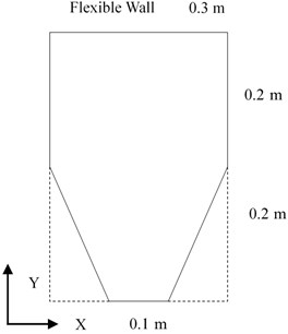
Fig. 4, shows the cross-section of the irregular geometry which is considered for the validation study. The dimensions of the irregular geometry are 0.3 m × 0.4 m × 1 m. The top wall (1 m × 0.3 m) is 5 mm thickness and flexible. Material properties and numerical modelling procedure of the structure and acoustic sub systems are same as the previous duct model The Flexible wall of the irregular geometry is modelled using simply supported boundary condition. FE modal analysis of uncoupled acoustic and uncoupled structural subsystem is done using commercial software (ANSYS15) [17] and post processing is done in ANSYS as well as MATLAB [18] as mentioned in Fig. 2. Total of 1080 nodes are considered on interface area of Structural-Acoustic coupling and total acoustic nodes are 25690. Obtained results from hybrid methodology are compared with numerical one.
Fig. 4Cross-sectional view of irregular geometry
4. Results and discussion
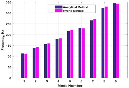
Table 1 shows the comparison of the coupled natural frequencies between the results obtained by hybrid methodology and analytical solution of rectangular duct with one wall flexible [3]. The results are in close agreement and maximum deviation of 2.7 % is observed up to 10 modes indicating, that hybrid methodology estimated the coupled frequencies very accurately. Fig. 5 shows the graphical comparison using bar chart.
Tables 2 and 3 shows the transfer factor by hybrid method and analytical method, respectively for rectangular duct. These results are in good agreement with analytical results. Coupled natural frequencies of irregular geometry obtained by hybrid methodology are compared with numerical results and are in close agreement with each other. Results of the same are listed in Table 4.
For first five modes maximum deviation of 0.9 % is observed. Hence, hybrid methodology is robust and accurate. Maximum transfer factor of 0.95 is observed between 2nd uncoupled structural mode and 1st uncoupled acoustic mode. Hence noticeable shift in the coupled frequencies is observed for irregular geometry, uncoupled structural mode of 180.4 Hz shifted to 186 Hz and uncoupled acoustic mode of 171.5 Hz shifted to 165.4 Hz. However other modes which have very low transfer factor remained unchanged. Transfer factor for rectangular duct as shown in Table 2 is not as significant for irregular geometry. However maximum transfer factor of 0.47 is observed between 1st acoustic and 2nd structural mode. This indicates that irregular geometries have higher transfer factor due to coupling between structural and acoustic modes and noticeable shift in their natural frequencies.
Table 1Comparison of coupled natural frequencies of rectangular duct with flexible wall obtained from hybrid methodology and analytical model
S. No | Analytical method (Hz) | Hybrid method (Hz) | % of Error |
1 | 111.5 | 112.4 | 0.84 |
2 | 141.7 | 137.9 | 2.7 |
3 | 158.9 | 156.1 | 1.7 |
4 | 182.3 | 179.1 | 1.7 |
5 | 221.3 | 217.1 | 1.8 |
6 | 228.5 | 230.2 | 0.7 |
7 | 270.5 | 265.3 | 1.9 |
8 | 328.8 | 322.8 | 1.8 |
9 | 341.8 | 344.3 | 0.7 |
10 | 399.9 | 392.2 | 1.9 |
Table 2Transfer factor for rectangular duct with one wall flexible by hybrid method
Uncoupled structural modal frequency (Hz) | ||||||
Mode 1 138.4 | Mode 2 154.2 | Mode 3 180.5 | Mode 4 217.5 | Mode 5 265.1 | ||
Uncoupled acoustic modal frequency (Hz) | Mode 1 114.3 | 0 | 0.469 | 0 | 0.021 | 0 |
Mode 2 228.67 | 0.041 | 0 | 0.328 | 0 | 0.118 | |
Mode 3 343 | 0 | 0.014 | 0 | 0.061 | 0 | |
Table 3Transfer factor for rectangular duct with one wall flexible by analytical method
Uncoupled structural modal frequency (Hz) | ||||||
Mode 1 138.4 | Mode 2 154.2 | Mode 3 180.5 | Mode 4 217.5 | Mode 5 265.1 | ||
Uncoupled acoustic modal frequency (Hz) | Mode 1 114.3 | 0 | 0.442 | 0 | 0.02 | 0 |
Mode 2 228.7 | 0.048 | 0 | 0.397 | 0 | 0.091 | |
Mode 3 343 | 0 | 0.016 | 0 | 0.073 | 0 | |
Table 4Comparison of coupled natural frequencies of irregular geometry with flexible wall obtained from FE model and hybrid methodology
S. No | FE solution (Hz) | Hybrid method (Hz) | % Error |
1 | 145.9 | 144.5 | 0.9 |
2 | 164.4 | 165.4 | 0.6 |
3 | 187.2 | 186.5 | 0.4 |
4 | 238.3 | 239.1 | 0.3 |
5 | 322.0 | 322.9 | 0.3 |
Table 5Transfer factor by hybrid method for irregular geometry with one wall flexible
Uncoupled structural modal frequency (Hz) | ||||||
Mode 1 145.7 | Mode 2 181.8 | Mode 3 242 | Mode 4 326.2 | Mode 5 434.5 | ||
Uncoupled acoustic modal frequency (Hz) | Mode 1 171.5 | 0 | 0.95 | 0 | 0.03 | 0 |
Mode 2 343 | 0.035 | 0 | 0.1 | 0.5 | 0.096 | |
Mode 3 470.5 | 0 | 0.016 | 0 | 0.093 | 0.4 | |
Fig. 5Bar chart comparing the coupled natural frequencies of rectangular duct with one wall flexible by analytical and hybrid method
5. Conclusions
Hybrid impedance and mobility methodology has been developed to study the free vibration analysis of structural-acoustic coupled systems with irregular geometry. This methodology has been developed by combining two uncoupled sub systems in terms of impedance and mobility to derive the coupled equation of motion. The coupled equation of motion converted in to the standard eigen value formulation for calculating natural frequencies and mode shapes. Uncoupled subsystem responses are expressed in terms of modal parameters using finite-element methods. Proposed methodology results have been validated by comparing with literature and numerical model results for a rectangular duct with a flexible wall configuration. Then, the same formulation has been extended for irregular geometry and results are compared with numerical model. The predicted results are in good agreement. This methodology helps in understanding the coupling phenomena between acoustic and structural modes in terms of the transfer factors. The possible modes to be coupled and extent of coupling between acoustic and structural modes are expressed in terms of transfer factor. The higher value of transfer factor indicates the strong coupling. The current formulation captures the closeness of acoustic and structural natural frequencies and spatial match between mode shapes in coupling behavior. The obtained impedance and mobility data can be used for further studies in identification of dominant critical parameters in coupled response. This information will be useful for designers to understand the critical modes in coupling. The developed hybrid methodology is an alternate way to analyze the physics of structural-acoustic coupled problem associated with irregular and complex geometries.
References
-
Warburton G. Vibration of a cylindrical shell in an acoustic medium. Journal of Mechanical Engineering Science, Vol. 3, Issue 1, 1961, p. 69-79.
-
Dowell E. H., Gorman G., Smith D. Acoustoelasticity: general theory, acoustic natural modes and forced response to sinusoidal excitation, including comparisons with experiment. Journal of Sound and Vibration, Vol. 52, Issue 4, 1977, p. 519-542.
-
Kim S., Brennan M. A compact matrix formulation using the impedance and mobility approach for the analysis of structural-acoustic systems. Journal of Sound and Vibration, Vol. 223, Issue 1, 1999, p. 97-113.
-
Kim S., Brennan Modelling a structural-acoustic coupled system with an equivalent lumped parameter mechanical system. Journal of Vibration and Acoustics, Vol. 121, Issue 4, 1999, p. 453-459.
-
Webster A. G. Acoustical impedance and the theory of horns and of the phonograph. Proceedings of the National Academy of Sciences of the United States of America, Vol. 5, Issue 7, 1919, p. 275-282.
-
Bloch A. Electromechanical analogies and their use for the analysis of mechanical and electromechanical systems. Electrical Engineers-Part I, Vol. 92, Issue 52, 1945, p. 157-169.
-
Gardonio P., Brennan M. On the origins and development of mobility and impedance methods in structural dynamics. Journal of Sound and Vibration, Vol. 249, Issue 3, 2002, p. 557-573.
-
Venkatesham B., Tiwari M., Munjal M. Analytical prediction of the breakout noise from a rectangular cavity with one compliant wall. The Journal of the Acoustical Society of America, Vol. 124, Issue 5, 2008, p. 2952-2962.
-
Mohamed Z., Wang X., Jazar R. Structural-acoustic coupling study of tyre-cavity resonance. Journal of Vibration and Control, Vol. 22, Issue 2, 2016, p. 513-529.
-
Atalla N., Bernhard R. Review of numerical solutions for low-frequency structural- acoustic problems. Applied Acoustics, Vol. 43, Issue 3, 1994, p. 271-294.
-
Kruntcheva M. R. Acoustic-structural coupling of automobile passenger compartment. World Congress on Engineering, Vol. 2, 2007, p. 1236-1241.
-
Puri R. S., Morrey D., Bell A. J., Durodola J. F., Rudnyi E. B., Korvink J. G. Reduced order fully coupled structural-acoustic analysis via implicit moment matching. Applied Mathematical Modelling, Vol. 33, Issue 11, 2009, p. 4097-4119.
-
Kropp A., Heiserer D. Efficient broadband vibro-acoustic analysis of passenger car bodies using an FE-based component mode synthesis approach. Journal of Computational Acoustics, Vol. 11, Issue 2, 2003, p. 139-157.
-
Sum K. S., Pan J. Effects of the inclination of a rigid wall on the free vibration characteristics of acoustic modes in a trapezoidal cavity. Journal of Acoustic Society of America, Vol. 119, Issue 4, 2006, p. 2201-2210.
-
Dongyan Shi, Ying Zhang, Xiuhai Lv Analysis of acoustic characteristics of arbitrary triangular prism and quadrangular prism acoustic cavities. Shock and Vibration, Vol. 2019, 2019, p. 4894610.
-
Louisell W. H. Coupled Mode and Parametric Electronics. Wiley, 1960.
-
ANSYS. User manual, Structural and Acoustics Analysis Guide. Ansys, 2015.
-
User manual MATLAB, Math Works Inc. Natick, Massachusetts, 2015.
About this article

