Abstract
Computer aided engineering analysis is commonly used to evaluate and improve the performance and reliability of the products in today’s manufacturing industry. Computer aided engineering analysis software use finite elements method in their solutions. The most significant problem in practicing these analyses is to form the mesh structure properly. The aim of this study is to research the effects of using surface and three-dimensional solid models in structural stress analysis. In this context, the maximum deformation in a square beam subjected to bending was calculated analytically and numerically. The solid model and surface model were created via CATIA. These models were analyzed under the same conditions in the static analysis module via ANSYS workbench. A difference of 1.32 % was detected between the numerical solution and the numerical displacement value of the surface model, and a difference of 11.84 % was detected between the numerical solution and the displacement value of the solid model. The difference between the von mises stress values of both models is approximately 30 %. In the parametric assessment conducted regarding the change in the mesh size, it was discovered that the results were affected by the mesh size significantly, and the mesh size and stress increased by 1550 % with the singularity problem in the solid model. In systems subjected to bending, using a shell mesh with 6 degrees of freedom is more advantageous in terms of solution time, operational capacity, stability and accuracy of the result.
1. Introduction
Computer aided engineering analysis software are actively used in order to develop and assess the reliability and performance of the products in the manufacturing industry [1]. These systems use the finite element (mesh) method in their solutions. In addition to many advantages of the finite element method, the accurate creation of the mesh model is still a crucial problem. The accuracy of the result directly depends on the suitability of the mesh model. Depending on the geometry, the mesh model can be created as line, shell and solid. The solid mesh has 3 and the shell mesh has 6 (UX, UY, UZ, ROTX, ROTY, ROTZ) degrees of freedom.
The biggest problem of the finite element method, which has been used for solving problems since 1970s, is the accurate creation of the mesh network. There are quite many scientific studies conducted on the completely automatic creation of the mesh structure and the definition of the procedure [2, 3]. Fenkli et al. [4] examined the mesh structure in the box beam-column combination. They observed that the mesh technique used in analyses, where the section changed and the parts with complicated geometries were assessed together, influenced the solution results. In such cases, they concluded that it would be right if the mesh production is executed manually and the decision on the size, form and intensity of the finite elements must be made by the designer. Yamato et al. [5] used machine learning to optimize the necessary operational parameters for mesh modification. They used HyperMesh of Altair Corporation which is a specific mesh production software used in the CAE industry for mesh production. Tomac and Eller [6]: The quality mesh structure was obtained with the comparison of the accurately calculated reference data through iterative solutions. Peeters et al. [7] researched the use of shell and solid mesh in possible parts in their study conducted on the wind turbine blades. They concluded that shell elements needed be used in possible parts. Pandya and Parey [8] touched upon the importance of the mesh structure. They discovered that the accurate stress value will be obtained if the mesh structure is formed in compliance with the geometry. Liu and Glass [9] stated in their study that mesh intensity is closely related to obtaining the accurate stress result. They revealed that a different mesh structure should be formed for different geometries, and the appropriate mesh structure should be selected in the modal, static and impact test. Fogg et al. [10] conducted a study to eliminate singularity, which is one of the biggest problems in mesh production. Singularity leads to obtaining results much higher than the real stress value. Park and Oh [11] explained that a shell element with 6 degrees of freedom should be used because solid elements in systems subjected to bending do not have rotational freedom. Yang [12] stated that all the 2D element types can be used independently or together with 3D element types in the modeling of 3D structures.
In this study, the deformation in a beam system subjected to bending was approached analytically and numerically. In this context, the beam system was defined. The system was solved analytically, and the maximum displacement value was calculated. Models were designed via CATIA. The models were imported to ANSYS workbench static analysis module. The necessary loading and limit conditions were defined for the analysis. The analytical result was compared to the numerical Ansys results. The change in the deformation, stress and skewness values depending on the mesh size was investigated.
2. Material and methods
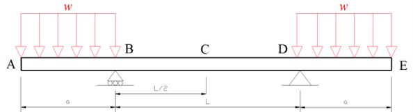
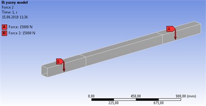
In this study, the 100 mm×100 mm×6 mm beam was used as the assessment sample. Profile material is St37. The total length is 2 m. 1 m, 0.5 m and 30 kN/m (Fig. 1).
Fig. 1Beam subjected to bending
2.1. Creation of the surface and solid models of the system
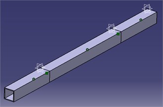
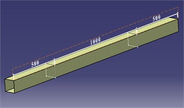
The solid model was created with CATIA part design and Assembly design modules (Fig. 2(a)). The surface model was created via CATIA in Generative shape design module (Fig. 2(b)).
Fig. 2a) Solid model assembly b) surface model
a)
b)
2.2. Analytical solution of the system
The beam and its loading are symmetrical to the midpoint and therefore the tangent at point is horizontal and it is used as the reference tangent. : angle, : moment area, : displacement, :
Slope of the beam at point E; (1st moment-area theorem):
Using Eq. (1):
Displacement in E; (2nd moment-area theorem):
2.3. Structural analysis via ANSYS
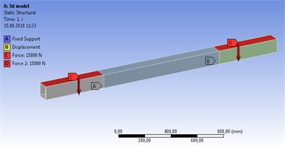
CATIA models were separately imported to ANSYS static structural analysis module. The same loading and limit conditions were defined (Fig. 3).
Fig. 3a) 3D model static analysis definition b) 2D model static analysis definition
a)
b)
2.3.1. ANSYS solid model analysis
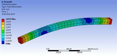
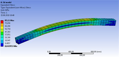
In Ansys solution of the solid model, the total deformation was found as 1.87 mm and the maximum von Mises stress as 85.11 MPa (Fig. 4).
Fig. 4Solid model structural stress analysis results a) Total def., b) Von Mises stress
a)
b)
2.3.2. ANSYS surface model analysis
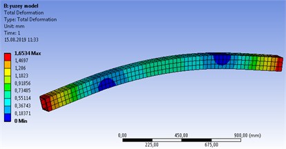
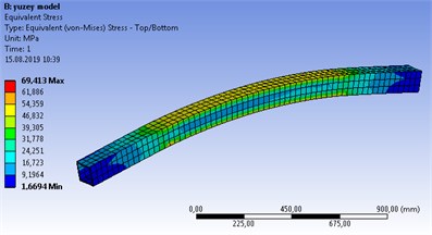
In Ansys solution of the surface model, the wall thickness of the surface was defined as 6 mm. The 3D mesh structure is seen when the mesh structure of this system, which is imported as the surface, is formed. For the surface model, the total deformation was found as 1.65 mm and the maximum von Mises stress as 69.41 MPa (Fig. 5).
Fig. 5Surface model structural stress analysis results a) Total def., b) Von Mises stress
a)
b)
3. Results and discussion
The solution of the problem related to the beam subjected to bending was achieved analytically and numerically. The analytical and Ansys solution results of the maximum deformation are seen in Table 1. There is a small difference as 1.32 % between the surface model and the analytical solution. The difference is 11.84 % as a result of the analysis performed with the solid model solution.
Table 1Solution method and maximum displacement values
Solution method | Analytical solution | Solid model solution | Surface model solution |
Total deformation (mm) | 1.672 | 1.87 | 1.65 |
Difference (%) | – | 11.84 | 1.32 |
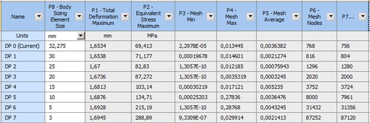
Software related to finite elements determine a mesh size based on the system capacity and geometry. This mesh value was decreased, and the change in the maximum stress, maximum displacement values, skewness values and element numbers were examined parametrically. In two analyses where shell and solid elements were used, the proportions of the deformation are close and acceptable. The first mesh size in the solid model (Fig. 6) and the surface model (Fig. 7) was the value defined by the software and the analysis was performed with 7 mesh sizes. The shell mesh skewness value is appropriate for the mesh value defined by the software. The solution where the skewness value was 0.5 for the solid mesh was found appropriate. The decrease in the mesh size increased the maximum stress values by 1550 % in the solid model and by 210 % in the surface model. The increase in the surface model is reasonable compared to the solid model. This increase in the stress results from the lined definition of the bearings and the occurrence of singularity. The maximum stress values are not accurate. For the solid model, the minimum mesh size that can be realized by computer is 3 mm (Fig. 6). As at least three elements must be available in a section, the adequate mesh size could not be achieved for the solid model. For this reason, a more capable processor is required.
Fig. 6 parametric solution took 28.06 mins for the solid model, and Fig. 7 parametric solution took 16.32 mins for the surface model. Time is saved by 42 % with the usage of the shell model.
When subjected to bending, shell elements have the ability to rotate. Therefore, stress concentration was much higher in the solid model.
Unfortunately for several systems, the solid model design is already available. Most of the time, it may be necessary to create a surface model for the surface model analysis.
It was seen that solid elements in this solid element exhibited shear locking. It is thus recommended that one should avoid using this type of element in bending applications analysis. There was, however, no such shear locking with fully integrated shell solid elements [14, 15].
Fig. 6Parametric solution depending on the mesh size for the solid model
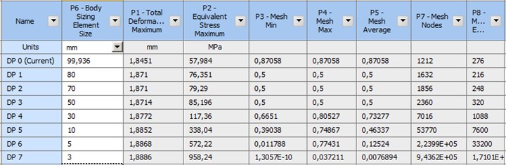
Fig. 7Parametric solution depending on the mesh size for the surface model
4. Conclusions
This study presents (Figs. 6, 7) that if the mesh structure is not selected correctly, the values that are far from the correct result will be obtained. The use of shell and solid elements exhibits great differences in the creation of the mesh structure and the stability of the results. In analyses with appropriate system geometries, it is advantageous to use shell mesh in terms of iterative mesh operation and processor capacity.
In finite element analysis, shell elements provide effective solutions and reliable results. The Shell mesh should be used especially when the size of an axis is less than 20 % compared to other axes.
Mesh structuring is easier in the surface model.
The result is affected by the change in the mesh size much less than the solid model is, and it is possible to analyze considerably thin surfaces with 2D model.
Almost 3 times more elements are needed in solid models for the same mesh size. Therefore, the need for the computer processor capacity is high.
It is advantageous to use shell mesh in terms of the processor need for big models.
Using shell elements decreases the solution period approximately by 40 %, which changes depending on the model complexity.
Especially in systems subjected to bending, surface elements should be preferred due to their 6 degrees of freedom. The three-dimensional solid elements exhibit shear locking when subjected to bending. The two-dimensional elements do not have such a shear locking problem.
References
-
Silori P., Shaikh A., Kumar K. C., Tandon T. Finite element analysis of traction gear using ANSYS. Materials Today: Proceedings, Vol. 2, 2015, p. 2236-2245.
-
Lisle T. J., Shaw B. A., Frazer R. C. External spur gear root bending stress: a comparison of ISO 6336:2006, AGMA 2101-D04, ANSYS finite element analysis and strain gauge techniques. Mechanism and Machine Theory, Vol. 111, 2017, p. 1-9.
-
Kalita K., Shinde D., Haldar S. Analysis on transverse bending of rectangular plate. Materials Today: Proceedings, Vol. 2, Issues 4-5, 2015, p. 2146-2154.
-
Fenkli M., Kımılı N., Çelik İ. D., Sivri M., Zeki A. the effect of mesh quality on shaping in box-section beam-column joints. Suleyman Demirel University Journal of Natural and Applied Science, Vol. 19, Issue 1, 2015, p. 34-39.
-
Yamamoto R., Takemoto Y., Ishikawa Y., Joe K. Optimization of auto mesh generation using genetic. International Conference on Parallel and Distributed Processing Techniques and Application, 2018.
-
Tomac M., Eller D. Towards automated hybrid-prismatic mesh generation. Procedia Engineering, Vol. 82, 2014, p. 377-389.
-
Peeters M., Santo G., Degroote J., Van W. High-fidelity finite element models of composite wind turbine blades with shell and solid elements. Composite Structures, Vol. 200, 2018, p. 521-531.
-
Pandya Y., Parey A. Failure path based modified gear mesh stiffness for spur gear pair with tooth root crack. Engineering Failure Analysis, Vol. 27, 2013, p. 286-296.
-
Liu Y., Glass G. Effects of mesh density on finite element analysis. SAE Technical Papers 2013-01-1375, 2013.
-
Fogg H., Sun L., Jonathan E. M., Armstrong C. M., Robinson T. T. Singularities in structured meshes and cross-fields. Computer-Aided Design Vol. 105, 2018, p. 11-25.
-
Park D. W., Oh S. I. A four-node shell element with enhanced bending performance for springback analysis. Computer Methods in Applied Mechanics and Engineering, Vol. 193, Issues 23-26, 2004, p. 2105-2138.
-
Yang K. H. Meshing, Element Types, and Element Shape Functions. Elsevier Inc., 2017.
-
Beer F. P. Mechanics of Materials. McGraw-Hill Higher Education, New York, 2009.
-
Dufva K. E., Sopanen J. T., Mikkola A. M. A two-dimensional shear deformable beam element based on the absolute nodal coordinate formulation. Journal of Sound and Vibration, Vol. 280, Issues 3-5, 2005, p. 719-738.
-
Sun E. Q. Shear locking and hourglassing in MSC, Nastran, ABAQUS. MSC Software Users Meeting, 2006.
Cited by
About this article

This study has been supported by the projects numbered Tübap 2019/47 and Tübap 2019/158, which are supported financially by Trakya University (Turkey), Coordination Unit of Scientific Research Projects.
