Abstract
Analysis of masonry buildings situated on seismic or mining activity terrains as well as subjected to dynamic human-induced vibrations and influences should base on the appropriated mechanical properties of masonry. There main parameters describing bending and shear stiffness’s of masonry shear walls are modulus of elasticity as well as shear modulus. Values of these parameters under seismic or cyclic loading are rapidly coming down due to the inelastic behaviour of the masonry. The problem of degradation of modulus of elasticity as well as shear modulus is presented and discussed based on the tests results of three types of clay brick masonry wall specimens subjected to compressive cyclic loads and some specimens under cyclic horizontally and vertical shearing (in one cycle) carried out at the Department of Structural Engineering of the Silesian University of Technology in Gliwice as well as results obtained by other researchers and available at the technical publications. As result there is proposed to determine the value of modulus of elasticity as 40 % of calculated with accordance with Eurocode 6 [1]. In case of shear modulus it is suggested to determine the values as 20 % of initial values of modulus of elasticity, that is mean 50 % less than recommended in current version of Eurocode 6 [1] and perfectly correct with requirements given in Eurocode 8 [2].
1. Introduction
Analysis of masonry buildings situated on seismic or paraseismic terrains as well as subjected to dynamic human-induced vibrations and influences should base on the appropriated analytical models and procedures allowing calculation of resistance and deformability of masonry shear walls. These methods should reflect both non-linear elastic-plastic-brittle behaviour of masonry in masonry buildings under seismic influences and the actual failure mechanism – see Tanrikulu et al. [3]. Acceptance in the calculations of masonry walls the values of mechanical parameters of masonry as given in Eurocode 6 [1], usually overstated because they take into account the elastic behaviour of the material, reduces the load-bearing capacity of shear walls and underestimates their deformability. From the safety point of view, such situation is not accepted.
Therefore, the mechanical quantities describing the real stiffness of masonry walls in typical design practice should be possible to take from the appropriate building standards. In case of seismic or paraseismic of loadings and influences is necessary to take into consideration that the main material properties of masonry, like modulus of elasticity as well as shear modulus under these types of loading are rapidly coming down due to the inelastic behaviour of the masonry. Unfortunately, this phenomenon is not taken into account in standard’s regulations: masonry code Eurocode 6 [1] but Eurocode 8 [2] in load bearing elements is recommended 50 % reduction of flexural and shear stiffness of the uncracked elements. This this problem has been discussed for many years by researchers and scientists, among others, Tomaževič [4], Tomaževič et al. [5, 6], Zimmermann et al. [7, 8], Vintzileou [9].
In such a situation, two solutions are possible: the proper values of mechanical quantities for calculation of resistance and deformability of masonry should be determined experimentally by using testing procedures on the basis on which these design and calculation methods were developed or values of modulus of elasticity and shear modulus, given in Eurocode 6 [1] should be modified for seismic, paraseismic and dynamic design of masonry walls.
It is possible to find in the technical literature some information about static and dynamic, cyclic and monotonic tests of different types of masonry specimens (piers, small wallettes, large-scale specimens, etc.) tested at different boundary conditions and made of different types of masonry units and mortars [3-11]. Therefore, it should be necessary to suggest appropriate recommendations for shear stiffness reduction and checking if suggested in Eurocode 8 [2] 50 % reduction is sufficient into design of one of the most popular type of masonry made of clay solid brick with cement-lime mortar.
2. Modulus of elasticity
2.1. Theoretical considerations
In engineering practice as well as in standards, masonry is usually treated as an isotropic material with linear-elastic characteristics. In case of the experimental determination of the modulus of elasticity , (based on the standard EN 1052-1 [12]) the problem of determining the value of the modulus of elasticity is then reduced to determining the tangent of inclination angle of the secant stress-strain relationship in the interval (usually from 0 to 0.33 where is the maximal value of compressive stresses – peak value), to the axis of deformation. Eurocode6 [1], like other European standards, determines this value as an initial modulus of elasticity. The limits of the range may be different, e.g. in the Scandinavian countries, a secant modulus in the range of stresses from 0.1 ) to ( 0.4 ) was usually determined.
In the absence of experimental data, Eurocode 6 [1] allows to determine the value of an ad hoc modulus of elasticity from the following relationship:
where is the coefficient depending of type of masonry units (specified in National Annexes or taken as table value given in [1]; in case of masonry made of clay solid bricks usually is taken 1000), and is the characteristic compressive strength of masonry (taken from tests carried out with the accordance with [12] or from the National Annex).
Obviously, such determined modulus of elasticity describes the behaviour of masonry as typical isotropic body, whereas the real behaviour of masonry is non-linear elastic-plastic with brittle failure. As stress builds up in the masonry, the value of Young’s modulus is changing due to the partial plasticity of the material and the development of micro cracks. According to the concepts of Continuum Damage Mechanics (see e.g. Murakami [13]), the effective stiffness represented by the value of Young’s modulus is changing by the variation of the damage variable :
where is the damage variable from the range (0 ≤ ≤ 1) and is the initial value of the modulus of elasticity for the elastic behaviour of the material. In case of masonry structures the value is taken as the tangent of inclination angle of the secant stress-strain relationship in the interval from 0 to 0.33 where is the maximal value of compressive stresses.
The damage factor is depending on the level of the internal compressive stresses and non-elastic behaviour of masonry. This is particularly evident in the case of cyclically compressed walls, where changes in material properties are mainly caused by the development of micro cracks. As a result, along with the increase of the state of stress and deformation of the wall, the value of the elastic modulus decreases abruptly – see Fig. 1 (taken from [14]).
Fig. 1Change of the elastic (secant or current) modulus of elasticity E of uniaxial cyclic compression of masonry wallettes as a function of a strain in vertical direction
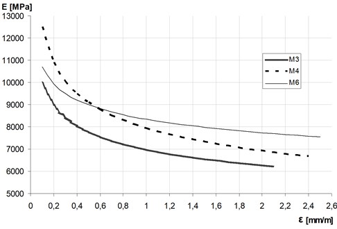
In case of masonry under axially cyclic compression, the damage variable usually is not a linear function of the strain – see Galman and Kubica [14]. The critical value of the damage variable is 0.5 and is generally reached at the point of fracture of the masonry sample. In case of masonry it is corresponding with the state of the visible cracks with width exceeding 3 mm. The theoretical maximum value is one and is corresponding with the state of failure connected with the fully destruction of the masonry. Therefore, in analytical and numerical calculations it is advisable to take the effective value of the modulus of elasticity, determined from the Eq. (2) for the appropriately calibrated value of damage parameter .
2.2. Test’s data and discussion of the problem
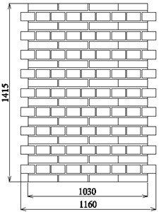
To verify the behaviour and changes of the mechanical properties of masonry made of solid clay bricks strength class “30” ( 30 MPa) and the most wide being in use, cement-lime mortar (1:1:6) strength class M5 research work were carried out by Galman [15] at the Department of Structural Engineering of the Silesian University of Technology in Gliwice. Partially, the results were presented in Kubica et al. [16]. Research programme has consisted of four series of wall specimens of shape and overall dimensions as shown in Fig. 2(a). Masonry wallettes had thickness 25 cm and English bond, which is typical and the most popular in Poland. First specimen, naming as MW-d were the reference number and was subjected to axially compression in one cycle. The other three series included specimens subjected to axially cyclic compression. Elements of series MW-c were loaded cyclically from zero up to failure with gradation of loading force in every cycle every 150 kN and unloading in any cycle to zero. In case of series MW-c-0.33 the compressive force also increased every 150 kN but after firs three cycles the unloading was realize up to the 1/3 of the expected maximal force, whereas in case of specimens of MW-c-0.67 series the unloading, after first 7 cycles, was realized up to the 2/3 of the expected maximal force. The expected maximal compressive force was determined by test of the reference specimen MW-d.
For all tested specimens were determined the envelope curve as it has presented in Fig. 2(b). It is visible the no-linear elastic behaviour of the tested masonry wallettes. During the tests were recorded the value of the compressive stresses and in-plane deformations in both orthogonal directions by the set of LVDT’s transducers, shown also in Fig. 2(a). Very carefully was recorded the moment of the first cracks appearance.
The main results of the tests as well as computational analyses are shown below in Table 1. The values of the initial modulus of elasticity were determined from the stress-strains curve relationship in the interval from 0 to 0.33, whereas the using Eq. (1). The values of correspond to the value of the elastic modulus, determined for the first cracks.
Fig. 2The shape and overall dimensions of: a) masonry wall specimens tested by Galman [15] with visible the localization of the set of LVDT’s transducer, b) typical stress-strain relationship for masonry subjected to cyclic loading of specimens of series MW-c with the construction of the envelope curve
![The shape and overall dimensions of: a) masonry wall specimens tested by Galman [15] with visible the localization of the set of LVDT’s transducer, b) typical stress-strain relationship for masonry subjected to cyclic loading of specimens of series MW-c with the construction of the envelope curve](https://static-01.extrica.com/articles/20417/20417-img2.jpg)
a)
![The shape and overall dimensions of: a) masonry wall specimens tested by Galman [15] with visible the localization of the set of LVDT’s transducer, b) typical stress-strain relationship for masonry subjected to cyclic loading of specimens of series MW-c with the construction of the envelope curve](https://static-01.extrica.com/articles/20417/20417-img3.jpg)
b)
Table 1The main results of the tests as well as computational analyses
Specimen | [MPa] | (Eq. (1)) [MPa] | [MPa] | |||
MW-d | 6951 | 10420 | 4434.04 | 1 | 0.64 | 0.43 |
MW-c-1 | 7714 | 10420 | 3976.00 | 1.11 | 0,57 | 0.38 |
MW-c-2 | 6813 | 10420 | 3532.08 | 0.98 | 0.51 | 0.34 |
MW-c-3 | 8771 | 10420 | 4336.03 | 1.26 | 0.62 | 0.42 |
MW-c-4 | 8342 | 10420 | 3538.78 | 1.20 | 0.51 | 0.34 |
MW-c-5 | 8783 | 10420 | 3649.45 | 1.26 | 0.53 | 0.35 |
MW-c-0.33-1 | 9263 | 10420 | 5623.38 | 1.33 | 0.81 | 0.54 |
MW-c-0.33-2 | 8261 | 10420 | 4900.47 | 1.19 | 0.71 | 0.47 |
MW-c-0.33-3 | 9150 | 10420 | 5141.59 | 1.32 | 0.74 | 0.49 |
MW-c-0.67-1 | 8222 | 10420 | 5252.14 | 1.18 | 0.76 | 0.50 |
MW-c-0.67-2 | 7012 | 10420 | 4273.06 | 1.08 | 0.61 | 0.41 |
MW-c-0.67-3 | 8171 | 10420 | 4411.52 | 1.18 | 0.63 | 0.42 |
Analysis of the comparison of the initial values of modulus of elasticity determined in cyclic tests with obtained in one-cycle test shows generally a little higher values representing cyclic loading. Furthermore the values of modulus of elasticity for the state of the first visible cracks by the reason of the not-elastic behaviour and micro cracking were not exceeds 75 % of the initial values (obtained from the tests) what corresponded with the acceptance of the damage factor in Eq. (2) at the level of 0.25. This same value of damage factor (for plastic and micro cracking of the material) is recommended in [17]. Whereas, the calculation of the Young’s modulus , specified in Eurocode 6 [1] (Eq. (1)) seems to be too high in relation to the experimental data (see the values shown in last column in Table 1). Therefore, in situation when in the calculations we have to rely on standard values and requirements, it is necessary to reduce the value of the elastic modulus by at least 60 % in relation to calculated from Eq. (1).
3. Shear modulus
3.1. Theoretical considerations
According to the most of European national masonry standards, including Eurocode 6 [1] in masonry structure analysis the value of shear modulus can be taken as:
where is an initial secant modulus of elasticity.
In case of in-plane shearing of masonry wall specimens, the value of the shear modulus may be determine based on the value of shear stresses and shear strains using the formula:
This relationship is particularly useful in situations where the displacement of the edge of the wall under the shear load is not directly measured, only the deformation parameters are measured in the middle area of the test element, e.g. in one cycle in-plane shear tests or diagonal compression tests according to ASTM E519/E519M-15 [20] standard.
In the case of testing the elements of walls subjected to cyclic shear, the shear modulus is usually determined based on characteristic parameters, among others, such as elastic stiffness , maximum horizontal force , geometrical data of tested specimens and taking into account the bending and shear deformations, can be calculating as:
where is the elastic stiffness of the wall; , , are the height, length and width of the wall specimen; is the floor area of the wall (), is the modulus of elasticity, is the coefficient for the boundary conditions ( 3 for cantilever and 12 for walls restraint on both sides) and is the shear stress coefficient (for rectangular cross section 1.2).
Of course, masonry is typical anisotropic body and the value of shear modulus is changing with accordance with the state of loading and deformation. Therefore, taking in calculations values of shear modulus according to Eq. (3) is equal with omission of plastic and damage deformation of masonry. In real structures and loading, including seismic and dynamic effects, the values of shear modulus, especially for higher levels of internal stresses, is significantly lower than obtained from Eq. (3). Therefore, such an overvalued determination of shear modulus is increasingly criticized in the literature on the subject [4-9] and [18]. It leads to serious underestimations of structure deformations, which is the basis for the analysis of limit states and safety of structures, e.g. calculated in accordance with Eurocode 8 [2] for seismic areas. Also, the American FEMA P440A [19] regulations also require consideration of material stiffness degradation when calculating buildings for seismic influences.
Therefore, in calculation and analysis of shear (stiffening) walls the following, based on the Continuum Damage Mechanics, reduced values of shear modulus is proposed:
where is the damage variable characterised the variation of the shear modulus and describing the kinetics of the plasticity and damage process of the masonry from the range (0 ≤ ≤ 1) and is the initial value of the modulus of elasticity for the elastic behaviour of the material.
3.2. Experimental results and its discussion
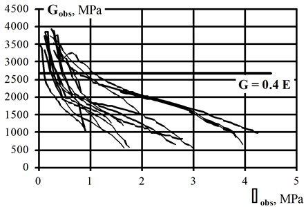
Then problem of shear stiffness degradation is analysed by author for many years, especially from the point of view of calculating masonry buildings in the areas of paraseismic influences caused by mining activity. There were carried out many tests of wall type specimens subjected to vertical or horizontal shearing with and without vertical precompression. All these tests concerned shearing in one cycle. Among others, series masonry wallettes made of clay solid bricks strength class “25” ( 25 MPa) and cement-lime mortar class M5 (1:1:6) were subjected to vertical shearing without and with six levels of precompression ( stresses). The shape and overall dimensions of tested wallettes is shown in Fig. 3(a). Thickness of the specimens was 0.25 m and English bond was used. All wall specimens were tested in one cycle up to the failure. During all tests were recorded the vertical shear force and in-plane deformations using set of LVDT’s transducers used in compression tests and shown in Fig. 2(a).
Fig. 3The shape and overall dimensions of: a) masonry wall specimens in author’s tests, b) relationship Gobs–τobs for tested wallettes
a)
b)
The main results as level of vertical compressive stresses , shear stresses noted for the first visible diagonal cracks and corresponding to them values of the shear strains are shown in Table 2.
Table 2The main results of the author’s tests with computational analyses
Specimen | [MPa] | [MPa] | [mm/m] | (Eq. (4)) [MPa] | (Eq. (3)) [MPa] | |
CMW-v-1 | 0 | 0.504 | 0.328 | 1536.6 | 2680 | 0.57 |
CMW-v-2 | 0.2 | 1.092 | 0.714 | 1529.4 | 2680 | 0.57 |
CMW-v-3 | 0.4 | 1.622 | 1.052 | 1541.8 | 2680 | 0.58 |
CMW-v-4 | 0.6 | 1.752 | 3.421 | 512.1 | 2680 | 0.19 |
CMW-v-5 | 1.0 | 2.579 | 3.088 | 835.2 | 2680 | 0.31 |
CMW-v-6 | 1.4 | 3.073 | 3.023 | 1016.5 | 2680 | 0.40 |
CMW-v-7 | 2.0 | 3.564 | 2.008 | 1779.9 | 2680 | 0.66 |
In the next two columns are presented values of shear modulus determined based on test data using Eq. (4) and based on standard recommendation, Eq. (3), respectively. The last column covers the comparison of these two determined values. It is easy to see the values of shear modulus received from tests are roughly half of the values calculated based on Eurocode 6 [1] recommendations. This results in 0.2. This means that the value of the damage factor , should be taken in this case as 0.5. The relationship for tested wallettes, presented the non-linear decrease of the shear modulus in relation to the vertical shearing stresses in graphical form with recommended in Eurocode 6 [1] value 0.4 is shown in Fig. 3(b).
Interesting cyclic shear tests of masonry wall specimens made of clay solid bricks with the dimensions of 290×140×65 mm corresponded to the old Austrian standard format and cement-lime mortar class M5 were carried out by Zimmermann et al. [8]. The shape of the wallettes of tested series was built with English bond and dimensions of 2390×2990×290 mm (length×height×thickness). In complementary material tests were determined the compressive strength of the masonry 6.52 MPa and modulus of elasticity 1522 MPa.
During the tests the load level of the normal force was determined with 1.30 MPa (20 % of the maximal value) to avoid the occurrence of a pure friction or compressive failure. The horizontal load was applied displacement-controlled, each with three similar displacement amplitudes in one dimension and a subsequent increase ±0.25 mm etc. until failure of the wall.
The results of the computational analysis are shown in Table 3. The tested values of the shear modulus were calculated using Eq. (5) based on the elastic stiffness taking into account the bending and shear deformations of tested wallettes (calculated for 90 % of the maximal horizontal forces from the hysteresis envelope. In fourth column are presented the values of shear modulus calculated using standard recommendation (Eq. (3)).
Table 3The main results of the Zimmermann et al. tests [8] with computational analyses
Specimen | [N/mm] | (Eq. (5)) [MPa] | (Eq. (3)) [MPa] | |
H-01 | 31.30 | 188.2 | 608.8 | 0.31 |
H-02 | 50.78 | 339.3 | 608.8 | 0.56 |
H-03 | 42.42 | 270.5 | 608.8 | 0.44 |
H-04 | 50.06 | 333.1 | 608.8 | 0.55 |
H-05 | 40.39 | 254.7 | 608.8 | 0.42 |
The comparison of the values of shear modulus received from tests were not exceeding 22 % of the calculated using Eq. (3). Thus, it could be assumed 0.22 – quite similar than in case of vertical shearing in one cycle. It could be taken that the value of the damage factor , should be taken in this case as 0.5. A similar results were obtained by the other researchers, among other in [4] are presented the test results of determination of the shear modulus in relation to the Young’s modulus. The values of G modulus vary from 6 % to 25 % of the elastic modulus and never have values as high as 0.4 , as specified and recommended in Eurocode 6 [1].
4. Conclusions
The results of all presented above computational analyses of the problem of stiffness degradation of clay brick masonry made of solid brick and cement-lime mortar under cyclic/seismic loads allow to formulate the following conclusions:
1) The degradation process connected with the non-elastic behaviour with development of the micro cracks, in case of both main parameters, modulus of elasticity and shear modulus gave this same effects;
2) The method of shear modulus determining, recommended in Eurocode 6 [1] leads to almost a double overestimation of their value in case of masonry under degradation. However, the reduction of stiffness by 50 % suggested in Eurocode 8 [2] in the discussed case of solid brick walls on cement-lime mortar is perfectly correct;
3) In case of the modulus of elasticity is proposed to determine the values using Eq. (2) with the damage factor 0.6, which gives 0.4, so the value is 60 % less than recommended in [1];
4) The process of shear stiffness degradation did not show any differences between the behaviour of the shearing masonry in one cycle in the vertical direction and subjected to horizontal cyclic loads. Therefore, it is proposed to determine the values using Eq. (6) with the damage factor 0.5, which gives 0.2 , so the value is 50 % less than recommended in [1].
References
-
EN 1996-1-1:2005 (Eurocode 6) Design of Masonry Structures – Part – 1-1: General Rules for Reinforced and Unreinforced Masonry Structures. CEN, 2005.
-
EN 1998-1:2005 (Eurocode 8) Design of Structures for Earthquake Resistance - Part 1: General Rules, Seismic Actions and Rules for Buildings. CEN, 2004.
-
Tanrikulu A. K., Mengi Y., Mcniven H. D. The non-linear response of unreinforced masonry buildings to earthquake excitations. Earthquake Engineering Structural Dynamics, Vol. 21, Issue 11, 1992, p. 965-985.
-
Tomaževič M. Earthquake-Resistant Design of Masonry Buildings. Series on Innovation in Structures and Construction – Vol. 1. Imperial College Press, London, 1999, p. 268.
-
Tomaževič M. Damage as a measure for earthquake-resistant design of masonry structures: Slovenian experience. Canadian Journal of Civil Engineering, Vol. 34, 2007, p. 1403-1412.
-
Tomaževič M. Shear resistance of masonry walls and Eurocode 6: Shear versus tensile strength of masonry. Materials and Structures, Vol. 2, Issue 7, 2009, p. 889-907.
-
Zimmermann T., Strauss A., Lutman M., Bergmeister K. Stiffness identification and degradation of masonry under seismic loads. 8th International Masonry Conference, Dresden, 2010.
-
Zimmermann T., Strauss A., Bergmeister K. Energy dissipation and stiffness identification of unreinforced masonry. 15th International Brick and Block Masonry Conference, 2012.
-
Vintzileou E. Unreinforced masonry Walls subjected to in-plane shear: from tests to codes and vice versa. Recent Advances in Earthquake Engineering in Europe, 16th European Conference on Earthquake Engineering Thessaloniki, 2018, p. 439-457.
-
Tomaževič M., Lutman M., Petkovič M. Seismic behaviour of masonry walls: experimental simulation. Journal of Structural Engineering, Vol. 122, Issue 9, 1993, p. 1040-1047.
-
Morandi P., Albanesi L., Magenes G. URM walls with thin shell/web clay units and unfilled head-joints: cyclic in-plane tests. Proceedings of the 2nd European Conference on Earthquake Engineering and Seismology, Istanbul, 2014.
-
EN 1052-1 Methods of Test for Masonry – Part 1: Determination of Compressive Strength. CEN, 1998.
-
Murakami S. Continuum Damage Mechanics. A Continuum Mechanics Approach to the Analysis of Damage and Fracture. Springer Verlag, 2010, p. 401.
-
Galman I., Kubica J. An attempt to describe the stiffness degradation of brick masonry subjected to uniaxially cyclic compressive loads. Technical Transactions, Civil Engineering (Czasopismo Techniczne, Budownictwo), Wydawnictwo Politechniki Krakowskiej, Nr 3-B/2016, p. 55-64.
-
Galman I. Masonry Walls Made of Ceramic Solid Clay Bricks Cyclically In-Plane Compressed Or under Out-Of-Plane Bending. Ph.D. Thesis, Faculty of Civil Engineering, Silesian University of Technology, Gliwice, 2012, p. 124, (in Polish).
-
Kubica J., Seweryn I., Wawrzynek A. Behaviour and characteristic of clay brick masonry wallettes subjected to compressive cyclic loads. 14th International Brick and Block Masonry Conference, Sydney, 2008.
-
Krajcinovič D. Damage Mechanics. North-Holland Series in Applied Mathematics and Mechanics, Vol. 41, Elsevier, Imprint North Holland, 1996, p. 774.
-
Kubica J. Analysis of masonry in complex state of stress – determination of scalar damage parameter. Archives of Civil Engineering, Vol. 52, Issue 2, 2006, p. 339-350.
-
FEMA P440A Effect of Strength and Stiffness Degradation on Seismic Response. Federal Emergency Management Agency, Washington, 2009.
-
ASTM E519/E519M-15 Standard Test Method for Diagonal Tension (Shear) in Masonry Assemblages. ASTM International, West Conshohocken, PA, 2015.
About this article

The work was created as part of the implementation of the BK-237/RB6/2018 Project financed by the Ministry of Science and Higher Education of Poland.
