Abstract
This article deals with the experimental verification of the power requirements of the tracked vehicle power unit while driving on a flat terrain. Requirements are based on results of a dynamic simulation. At first, the article presents the description of the simulation model, including the virtual terrain, on which the vehicle was moved. Second, a description of the experiment performed directly on the real prototype is presented. Measured variables were flow rates and pressures in the hydraulic system, whereby the power transmission from the engine to drive sprockets of four tracked undercarriages is ensured. Finally, there is the comparison of the calculated and measured time-power characteristics. The results correspond to each other.
1. Introduction
Correct determination of power requirements for a power unit of a transport machine is an important stage during its development. The possibilities to create a virtual prototype using computational methods, such as multi-body simulation with rigid or flexible structures [1, 2], make it possible to estimate these requirements in different operational situations [1]. Namely, it is the operation mode of the machine, loading and unloading, and the driving mode, for example the movement of the fully loaded machine through a different terrain. The examined machine is a forwarder [3], which has four tracked undercarriages (see Fig. 1). This machine is designed for transporting wood from a forest, mostly on a forest road. In the following chapters, the virtual prototype of forwarder and the dynamic simulation of its movement through the plain terrain are presented. Next, the description of the experiment and its evaluation are presented too. Finally, there are presented time-power characteristics obtained from the dynamic simulation and from the measured flows and pressures in the hydraulic system of the machine. The comparison of the simulation and the experiment is quantified using average values obtained from above-mentioned time characteristics in range from 10 to 50 seconds.
Fig. 1Real prototype of forwarder with four tracked undercarriages (without the load) [3]
![Real prototype of forwarder with four tracked undercarriages (without the load) [3]](https://static-01.extrica.com/articles/19939/19939-img1.jpg)
2. Computational model and dynamic simulation
In order to solve the dynamic simulation, the model of the machine – forwarder and the virtual terrain – flat plain surface was created.
The computational model of the forwarder with four tracked undercarriages is based on the CAD model of this machine and it is conceived as a two-frame articulated vehicle. From the point of view of dynamic simulation, the presented model can be split into two main parts.
The first part consists of the front frame and the rear frame and the joint that connects them together. A cabin, engine, fuel tank etc. are placed on the front frame. Bunk and the load in the form of several cylinders representing the real load - tree trunks with a maximum diameter of 0.3 m and length about 5 m are placed on the rear frame. In the dynamic simulation there are three bodies connected by two revolute links. More detailed information can be found in [1].
The second part consists of four tracked undercarriages (tracked units) [4]. Each undercarriage consists of the support frame, two arms, the drive sprocket, the tensioning device with the idler, four bottom rollers and the rubber track. All of the above-mentioned components stand out as separate bodies connected to each other by 9 revolute links and 1 prismatic link. In addition, the model for simulating the drive of the drive sprocket and the hydraulic piston of the tensioning device are used. The rubber track is created from 74 bodies (segments) connected to each other by revolute links with the viscoelastic torsion member for the accumulation and dissipation of the energy, which gives to the track a similar behavior as its real counterpart has.
The virtual terrain corresponds to a straight peaved road of 90 m length. Generally, a virtual terrain is a part of computational model, which is based on a real terrain and obstacles, and moving through this terrain has to raise acting forces on the vehicle. The methods of creating virtual terrains for the dynamic simulations needs of the wheeled transport machines movement are described in detail in [5].
Fig. 2Computational model of the forwarder with the description of main parts (with the load): 1 – load (weight), 2 – rear frame with bunk, 3 – track, 4 – roller, 5 – frame of tracked undercarriage, 6 – arm, 7 – hydraulic drive with drive sprocket, 8 – joint (break is not shown), 9 – front frame, 10 – idler, 11 – crane, 12 – driver, 13 – flat terrain
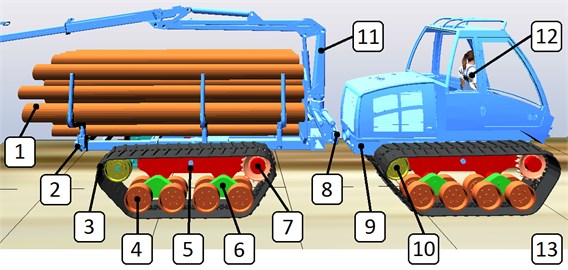
The computational model within virtual terrain, was created using Project Chrono [6] and its graphical representation is shown in Fig. 2, including the description of the individual parts. SOR was chosen as a solver. Due to solve the contact task between all bottom rollers and the track and between the track and terrain, maximal allowable time step value was set on 0.00025 s. The movement of the machine was ensured by rotating the drive sprocket on which torque was acting. Instant value of acting torque was controlled by the PID controller which was used to accelerate the machine from 0 m/s to 1 m/s and then to brake again to 0 m/s. All values of acting torque and angular speeds of drive sprockets were recorded. The power was calculated as the product of the angular speed and the torque of individual sprockets. With regard to the way in which it was assumed that experiments will be carry out, two dynamic simulations were performed. First, the empty forwarder (with a total weight of 9500 kg) drives on the virtual terrain at a speed of 1 m/s. Second, the loaded forwarder (with a total weight of 13100 kg) drives on the virtual terrain at a speed of 1 m/s. Fig. 3 shows the time-power characteristics of the power required for the driving mode of the machine.
Fig. 3Calculated time-power characteristics in range from 10 to 50 seconds: a) driving at a constant speed of 1 m/s without the load, b) with the load
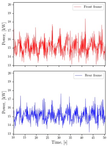
a)
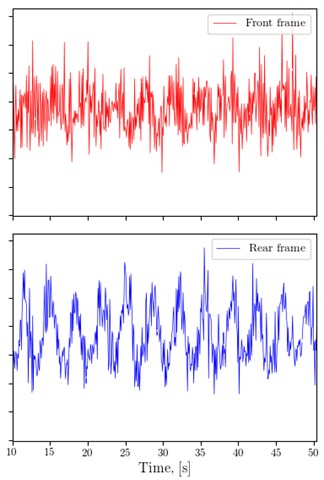
b)
3. Experimental testing of the prototype
Manufacturing of the real prototype of forwarder (see Fig. 1) was performed by a machine-engineering company Strojírna Novotný. The virtual model and calculated results of the operating parameters were taken into account. This prototype was experimentally tested for the power requirements and fuel consumption during the operation and driving mode on a flat terrain with a peaved surface with a slope up to 1 degree and a length of 85 m. All test results are available in [3].
The machine’s driving mode was chosen, because the machine's operation mode (loading and unloading tree trunks) does not achieve such energy demands. Forwarder is driven hydrostatically. The machine has two hydro-generators and four hydro-motors with the high efficiency, more than 90 %. Each hydro-generator pumps the hydraulic oil through a flow divider with a uniform division ratio to the front and rear pair of tracked undercarriages, respectively.
During the experiment two pressures were measured in the hydraulic system, before the hydro-motor and behind the hydro-motor. The hydraulic oil flows were measured too. The power was calculated as the product of the pressure difference with the hydraulic oil flow. The machine speed was 1 m/s and it was controlled by the operator (driver). The total weight of the unloaded machine was 9670 kg. The total weight of the loaded machine was 13320 kg (3650 kg was the load weight).
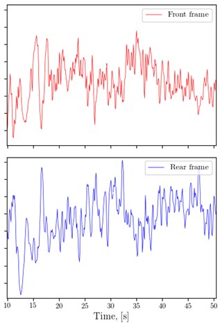
Fig. 4 shows the time-power characteristics obtained during the driving mode of the machine. It should be noted, while the sampling frequency of time characteristics obtained from simulations were relatively high (400 Hz), the sampling frequency of time characteristics presented below was lower (10 Hz).
Fig. 4Time-power characteristics obtained from experiment in range from 10 to 50 seconds: a) driving at a constant speed of 1 m/s without the load, b) with the load
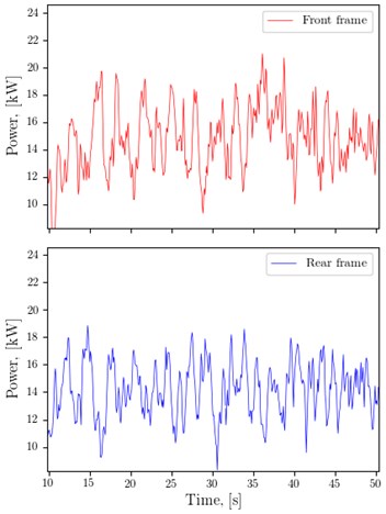
a)
b)
4. Discussion
Before evaluating obtained results, it should be noted, that in the case of the dynamic simulation the efficiency of the hydraulic drive system has not been taken into account, because losses of the installed hydro-motors are only up to 10 %. However, presented average values of power obtained from the dynamic simulation are greater than values obtained from experimental tests about 4 % and 1 % for the driving without the load and with the load, respectively. This fact is given by the parameters that describe the model of a rubber track, because these parameters were estimated only from a limited amount of information. Despite this fact, a good agreement can be observed among the results, which are shown in Table 1.
Table 1Average values of power obtained from above-mentioned time-power characteristics
Power taken for the driving without the load, [kW] | Power taken for the driving with the load, [kW] | |
Simulation – front frame | 15.136 | 16.745 |
Simulation – rear frame | 15.136 | 16.719 |
Experiment – front frame | 14.755 | 15.684 |
Experiment – rear frame | 14.205 | 17.493 |
5. Conclusions
In this article the results of the forwarder driving mode obtained from the dynamic simulation and the experiment were presented. The monitored parameter was the power, which is needed to drive forward on a flat surface. Although, a good match between simulation and experiment has been achieved, it should be noted, that this is only a basic case of the driving mode in a flat terrain. In the future, other time characteristics corresponding to driving in more challenging off-road conditions will be evaluated. It is assumed that if more than one measurement is available under different conditions, it will be possible to determine the degree of match between simulated and real driving mode more accurately and it will also be possible to better assess the credibility of the entire forwarder computational model.
References
-
Kašpárek J., Pokorný P. Analysis of the dynamics of a virtual prototype wheeled transport machine. Proceeding of International Conference Transport Means, Vol. 2014, 2014, p. 99-102.
-
Novotný P., Dlugoš J., Prokop A., Řehák K., Raffai P. Effective computational model for a solution of turbocharger rotor dynamics. Journal of Vibroengineering, Vol. 19, Issue 2, 2017, p. 724-736.
-
Neruda J., Ulrich R., Kupčák V., Pajkoš M., Zemánek T., Nevrkla P., Fiľo P., Klepárník J., Policar J., Škopán M., Pokorný P., Kašpárek J., Jonák M., Novotný V., Novotný T., Klimeš P., Sládek P. Research of the Variable Forward Tractor LVS 511. Tribun EU s.r.o., Brno, 2017, p. 195, ISBN 978-80-263-1086-0, (in Czech).
-
Kašpárek J., Jonák M., Škopán M. Design of the tracked chassis module. Transport Means, Vol. 2017, 2017, p. 666-670.
-
Kašpárek J., Jonák M. Advanced approaches for modeling of a virtual terrain. Proceeding of International Conference Transport Means, Vol. 2015, 2015, p. 37-40.
-
Tasora A., Serban R., Mazhar H., Pazouki A., Melanz D., Fleischmann J., Taylor M., Sugiyama H., Negrut D. Chrono: an Open Source Multi-Physics Dynamics Engine. High Performance Computing in Science and Engineering – Lecture Notes in Computer Science, Springer, 2016, p. 19-49.
About this article

The research leading to these results has received funding from the Ministry of Education, Youth and Sports under the National Sustainability Programme I. (Project LO1202) and with help of the project FSI-S-17-4104 granted by specific university research of Brno University of Technology. The authors gratefully acknowledge this support.
