Abstract
The paper deals with research of an engine block load caused particularly by inertia effects of the crank train rotating parts. Substantial reduction of this load can be achieved by an appropriate design of the crankshaft counterweights. The relation between crank train internal moments of rotating parts and the engine block load is investigated in the case of an I4 MPI engine with two variants of the crank train design. Used methodology is based on MBS simulations, where modally reduced flexible bodies and computational model of a hydrodynamic bearing are included.
1. Introduction
During the engine operation, the engine block is loaded, mainly, at crankshaft main bearings and this load can be described as a force effect obtained by numeric integration of a pressure field at the bearing hydrodynamic film.
This type of loading is investigated in the case of an aluminium deep-skirt engine block of modern 1.6-litre naturally aspirated spark-ignition in-line four-cylinder engine. The engine is considered in two variants: the standard one and the variant with reduced friction losses. The reducing of crank train friction losses is achieved by a reduced number of crankshaft main bearings from 5 to 3 [1]. The new 3-main-bearing (3mb) crankshaft is based on a 5-main-bearing (5mb) version of the standard engine.
In order to simulate the influence of the standard crank train variant and the new crank train variant upon the engine block load, the up-to-date computational methods are used and parametric studies are carried out.
2. Simulations of crank train dynamics
For simulation of crank train dynamics, a complex computational model of an engine (i.e. a virtual engine) is used. The dynamics is solved in the time domain which enables different physical problems, including various non-linearities, to be incorporated. The virtual engine is assembled as well as numerically solved in MBS (Multi-Body System) ADAMS which is a general code [2, 3].
In general, the virtual engine includes all significant components necessary for dynamics analyses. The included module is a crank train, a valve train, a timing drive and a rubber damper [4]. Following analyses deal with the crank train as a main module of the virtual engine.
The crank train module consists of solid model bodies, linearly elastic model bodies and constraints between them. Solid model bodies – defined by location of centre of gravity, mass, and inertia tensor – are a piston assembly, a connecting rod assembly, and a dynamometer rotor. The linearly elastic model bodies are modally reduced finite element models suitable for dynamic simulation [5-7]. These are: crankshaft, crankshaft pulley, flywheel, engine block, cylinder head, crank train sump, gear case. Cast-iron main bearing caps are included as an integral part of the engine block (different materials are considered) because the model of preloaded screws cannot be incorporated for this purpose.
The computational model of block of the 3mb variant is derived from the standard one by necessary design modifications; therefore, changes in dynamic behaviour of the 3mb block are included in the virtual engine as well.
The interaction between the crankshaft and the engine block is ensured via a non-linear hydrodynamic journal bearing model [8, 9].
Virtual engine is excited by means of cylinder pressure, defined by high-pressure measurement, and via inertial forces from moving parts. Simulations start from 1000 rpm and are carried out to 6200 rpm. Unlike simulation models with significantly reduced the number of degrees of freedom [10, 11], the virtual engine containing flexible bodies can bring complex results concerning 3-D vibration of the structure.
3. Main bearings load
The comparison of main bearing reaction forces for 5mb and 3mb variants, obtained from the virtual engine is performed. The maximum of main bearing reaction force means the greatest magnitude of this vector during a working cycle for respective rpm.
The most loaded main bearings of the 5mb variant are bearings 2 and 4. However, there is an obvious a growth in the middle main bearing. The most loaded bearing of the 3mb variant is the middle bearing. More analyses also show a special importance of the middle main bearing for the engine block load; therefore, further attention is paid to this bearing.
4. Engine block load in the middle main bearing
The crank train main bearing load is caused by gas forces, inertia forces, and their dynamic effects [12]. For desired power curve, the gas forces cannot be markedly changed. In order to affect the main bearing load, the only inertia forces must be considered. Inertia forces originate in:
• Reciprocating parts,
• Rotating parts.
Since inertia forces of reciprocating parts can be balanced only by using a balancing unit actually and such unit is not included in the engine layout, just inertia forces of rotating parts are further considered.
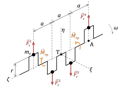
Inertia forces of rotating parts and its internal moments of discretized I4 engine are shown in Fig. 1, where is mass of rotating part reduced to the crank pin at crank radius and is a cylinder distance.
Fig. 1Inertia forces of rotating parts and corresponding internal moments at an I4 engine
If crank train deformations are neglected, angular velocity is considered to be constant and masses of particular crank train parts are supposed to be the same, the sum of rotating parts inertia forces is given by:
Resulting force is zero and reference point for resultant moment identification can be, therefore, chosen arbitrarily. By using the right-hand rule, the sum of moment with respect to the point A according to Fig. 1, for instance, can be obtained by:
Zero resulting moment means that the car body is not excited by this crank train effects, however, these effects are disturbed inwards. If the crank train is divided by plane going through the crank train decision point , see Fig. 1, two twin-cylinders are virtually obtained in the mirror form. Resulting force of rotating parts of each of them is zero, while their resulting moment is not zero with magnitude:
and its vector rotates with crankshaft. Regarding the mirror form, both vectors have the identical magnitude but opposite direction and they are disturbed largely in the middle bearing.
Permanent load of the middle main bearing, owing to inner moments of rotating parts, can be reduced by lowered rotating parts mass and by suitable counterweights.
The solution consists of balancing a twin-cylinder resultant moment of rotating parts; therefore, only 4 counterweights are required. This design brings load reduction for the middle main bearing in particular. However, crankshaft can be lighter. The 5mb and 3mb crankshafts are designed like this.
Crankshafts of worldwide engine manufacturers used to be also designed as the above mentioned combination, where bigger 4 counterweights are situated at crank webs adjacent to the first, the middle, and last main bearing and other crank webs are equipped by smaller 4 counterweights.
The discretization of the crank train rotating parts according to Fig. 1 is not very suitable for purposes of the engine described due to crank throw asymmetry caused by unilateral counterweight and a skew lightening bore of a crank pin. The splitting into two twin-cylinders is used and their product moment of inertia is further considered.
The product moment of inertia of a twin-cylinder is described by:
where is the product moment of inertia of a twin-cylinder crank throws, determined from crankshaft CAD model, and is the product moment of inertia of rotating parts of a connecting rod couple given by:
where is mass of rotating parts of a connecting rod assembly. In fact, the product moment of inertia is not a vector. However, if general moment of an inertia couple is expressed for unit angular velocity ( 1 rad∙s-1), its dimensionality corresponds to the product moment of inertia. Product moments of inertia of the 5mb and 3mb variants are determined this way.
In order to describe influence of counterbalances’ size upon the middle main bearing load, a variant 3mb-c is derived from 3mb by attaching 0.05 kg mass points directly on each counterweight of a modally reduced crankshaft. The influence of this modification upon the product moment of inertia of a twin-cylinder is determined by a position of these points with respect to each other and to crankshaft axis of rotation.
The dynamic behaviour of variants 5mb, 3mb, and 3mb-c is simulated by the virtual engine and magnitude and direction of the middle main bearing load is investigated.
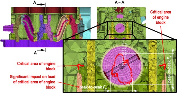
The deep-skirt engine block of the engine presented is equipped by separate main bearing caps. Each cap is connected with the block via highly preloaded screw couple. The cap position in the block is ensured by side facets with a transition fit.
In spite of the screw preload, a slide side movement of the cap towards the block can occurs as a consequence of the bearing load and thermal distortions when engine operates. The movement introduced can cause a fatigue crack in the groove, which is the critical area of the engine block, see Fig. 2.
Only bearing load reduction is required for fatigue crack elimination on this engine and the problem is peak-to-peak value of the bearing transverse force. A polar diagram of the middle main bearing load is shown in Fig. 2. The coordinate system is linked to the engine block, therefore, peak-to-peak value of affects fatigue life at critical areas.
Fig. 2Detail of the middle bearing load
The bearing load is influenced, especially, by gas forces at lower speed. This way of load is not critical for this engine type because strength of cast-iron bearing cap is sufficient also for the 3mb variant.
The situation at higher speed is described in Fig. 3. In spite of markedly lightened piston and connecting rod assemblies, the inertia forces dominate in the middle bearing load at 6200 rpm. A wide peak-to-peak value of transverse bearing load can be observed at all variants. This is caused, particularly, by the inner moments of rotating parts. The meaning of these moments is clearly shown in Fig. 3, where significant decrease of peak-to-peak value of transverse force appears at 3mb-c variant. The conjoined reduction of load in vertical direction is favourable because this load affects contact pressure and then friction force between the cap and block in the negative.
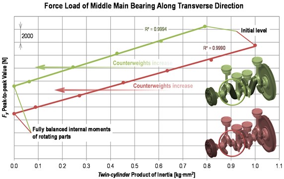
The influence of a twin-cylinder product moment of inertia upon peak-to-peak value of the transverse force in the middle main bearing at 6200 rpm is shown in Fig. 4. The graph describes results of a parametric study in terms of the crank train dynamics simulation. The load dependence on the product moment of inertia (counterweight mass, respectively) is almost perfectly linear.
A wider peak-to-peak value of the 3mb variant caused by bearings 2 and 4 absence is obvious. The product moment of inertia sensitivity is, however, relatively marked, while the initial size of counterweights is small. Therefore, further increase in size of counterweights can bring an important reduction of load at critical areas of the engine block.
Fig. 3The middle main bearing load during one working cycle at 6200 rpm
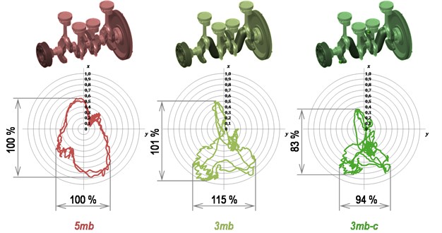
Fig. 4Dependence of transverse load of the middle main bearing upon a twin-cylinder product moment of inertia
It is efficient to concentrate a counterweight material as far as possible from crankshaft axis. A counterweight size is restricted by a piston cooling spray jet and a crank case design, respectively.
5. Conclusions
Advanced computational methods are efficient tools for understanding complex dynamic effects concerning not only the crank train, but also other engine subsystems. The study described shows the utilization of these methods for investigation the engine block load by means of crank train rotating parts. The results reflect the meaning of inertia forces for engine block load at a naturally aspirated I4 MPI engine. The analysis output can be effectively used by crankshaft designers as it enables to reduce a number of crankshaft variants respecting the engine block load for both the standard engine and the experimental engine with lowered main bearings number.
References
-
Drápal L., Novotný P., Maršálek O., Raffai P., Píštěk V. A Conceptual study of cranktrain with low friction losses. MECCA – Journal of Middle European Construction and Design of Cars, Vol. 11, Issue 2, 2013, p. 6-11.
-
Novotný P. Virtual Engine – A Tool for Powertrain Development. Inaugural Dissertation, Brno University of Technology, Czech Republic, 2009, p. 92.
-
Novotný P., Píštěk V. New Efficient Methods for Powertrain Vibration Analysis. Proceedings of the Institution of Mechanical Engineers, Part D, Journal of Automobile Engineering, Vol. 224, Issue 5, 2010, p. 611-629.
-
Rebbert M. Simulation der Kurbewellendynamik unter Berücksichtigung der hydrodynamischen Lagerung zur Lösung motorakusticher Fragen. Ph.D. Dissertation, Rheinisch-Westfälischen Technischen Hochschule, Aachen, Germany, 2000, p. 110, (in German).
-
Prokop A., Řehák K. Virtual prototype application to heavy-duty vehicle grearbox concept. Engineering Mechanics, Svratka, Czech Republic, 2017, p. 810-813.
-
Prokop A., Kopečková B., Řehák K. Gear drive system simulation of input parameters effect on rattle. Springer Proceedings in Physics. Acoustic and Vibration of Mechanical Structures, 2017, p. 381-388.
-
Novotný P., Prokop A., Zubík M., Řehák K. Investigating the influence of computational model complexity on noise and vibration modelling of powertrain. Journal of Vibroengineering, Vol. 18, Issue 1, 2016, p. 378-393.
-
Butenschön H. J. Das hydrodynamische, zylindrische Gleitlager endlicher Breite unter instationärer Belastung. Ph.D. Dissertation, Universität Karlsruhe, Germany, 1976, p. 219, (in German).
-
MSC.SOFTWARE. ADAMS/Engine Help. Version MD Adams R3. MSC Software Corporation, Newport Beach (CA), 2008.
-
Kučera P., Píštěk V. Torsional analysis of the engine computational model. Vibroengineering Procedia, Vol. 16, 2017, p. 25-28.
-
Kučera P., Píštěk V. Longitudinal and lateral dynamics of a commercial vehicle in Simulink software. Proceedings of International Conference Transport Means, Kaunas, Lithuania, 2015, p. 458-461.
-
Heisler H. Advanced Engine Technology. 1st Edition. Arnold, Oxford (Great Britain), 2002, p.794.
About this article

The research leading to these results has received funding from the MEYS under National Sustainability Programme I (Project LO1202) and Specific research project of the Faculty of Mechanical Engineering, Brno University of Technology (FSI-S-17-4104).
