Abstract
The negative pressure valve EGR bears thermal load for a long period, thus its heat transfer characteristics have an important impact on the stability of the engine. The fluid solid coupling method was employed to analyze the contact heat transfer between the inner cavity of the valve and the cooling water as well as the high temperature gas based on CFD. As a result, the characteristics of the internal fluid velocity field, pressure field and temperature field were obtained. Besides, the heat transfer capability of the valve was also improved by adding the annular cooling water channel. The test results showed that the calculation method has a high calculation accuracy providing an important basis for the optimization design of valves.
1. Introduction
The EGR valve is an essential exhaust re-circulation device installed on both gasoline and diesel engines. The working environment of the EGR valve is abominable and the temperature of the valve is high. If the analysis of the temperature field was not carried out before the design, the temperature of the components in installation location would not be clear resulting in the absence of the design basis or mistakes in material selection and design. Therefore, temperature field analysis and thermal calculation before the design of relevant products is crucial in ensuring the success of design and development [1, 2]. In recent years, researches at home and abroad were mainly focused on the cooling water jacket of diesel engine cooling system and the fluid solid coupled heat transfer of diesel engine cooling system. However, the fluid solid coupling researches of EGR valve was less. And the existing research is mainly focused on the flow of fluid flow inside the EGR [3]. For instance, L. V. Zhengtao carried out numerical simulation and experimental research on the fluid inside the EGR valve. But only the flow law of fluid flow inside the valve was studied and the influence of fluid solid coupling heat transfer on the valve structure design of EGR system has not yet been involved.
In order to solve problems mentioned above, the TE603 model of negative pressure EGR valve produced by a company was studied in this paper. ICEM software was employed to mesh the coupling system model constituted of the valve body, the valve stem, the high temperature gas and the cooling water of EGR valve. In order to achieve the heat transfer between fluid and solid, the interface was coupled so as to realize the calculation of the temperature field of the solid domain and fluid domain in the single calculation model. In the simulation process, the maximum opening valve was chosen. In the end of simulation, two cases that with and without cooling water were studied and the temperature field of the valve body and stem were obtained. After comparing and analyzing results obtained in two cases, proposed to increase adding cooling water gallery in upper valve body was proposed. In this case, the results in experiment and simulation further showed this proposal could greatly improve the heat transfer condition for the valve body meeting the temperature requirements of the sealing ring and other attachments in the upper valve body.
2. Fluid solid coupling heat transfer equation
2.1. Analysis on fluid solid coupling heat transfer
The coupling heat transfer system of negative pressure valve EGR includes the coupling heat transfer between solid and fluid (cooling water, high temperature gas and valve body, high temperature gas and valve stem), coupling heat transfer between solid and solid (valve stem, graphite pad and valve body) and the convection heat transfer between valve body and the air. Concerning the convection heat transfer between fluid and solid, the thermal boundary conditions cannot be given in advance owning to the interaction between the fluid and the wall. This kind of thermal boundary condition which could only be determined by the heat exchange process dynamically but could not be given in advance is called the fluid solid coupling conjugate heat transfer system. Therefore, the analysis of the temperature field of the negative pressure valve ERG should take both the heat conduction and the thermal convection into consideration [4]. To be more exact, the contact boundary between the inner cavities of valve body the cooling water as well as the high temperature gas should be considered as the fluid solid coupling conjugate heat transfer. The definitions of components and relevant physical parameters of the coupling heat transfer system model are shown in Tab 1.
2.2. The principle of fluid solid coupling heat transfer
The flow and heat transfer process of the cooling water and high temperature gas respectively in the upper and the lower part of EGR valve body could be classified in three physical problems: (1) the turbulent flow of incompressible viscous fluid in the valve body; (2) the convection heat transfer between the incompressible viscous fluid and the wall; (3) the heat conduction among the upper valve body, the lower valve body and the graphite pad machine body. In this case, these problems could be described respectively by three mathematical models which are the fluid flow, the fluid convection heat transfer and the solid heat conduction. Therefore, the fluid solid coupling conjugate heat transfer model of EGR valve constitutes of the flow and heat transfer model of cooling water and high temperature gas, the solid heat conduction model and the cooling water and the conjugate heat transfer model of the complex joint surface between cooling water and high temperature gas and the valve body [5].
2.2.1. The governing equation of fluid flow
For the flow and heat transfer calculation of cooling water and high temperature gas in EGR valve, it could be regarded as the turbulent flow of three-dimensional steady incompressible viscous fluid. Thus, the mass conservation equation, momentum conservation equation, energy conservation equation and the control equations such as the standard turbulence model - could be employed to solve the problem.
2.2.2. The heat transfer governing equation in fluid domain
The flow and heat transfer of fluid could be described by using the principle of energy conservation and shown as in Eq. (1):
where is the fluid density, kg/m3; is the enthalpy of fluid, J/kg; is the velocity of flow, m/s; is the pressure, Pa; is the time, s.
2.2.3. The heat transfer governing equation in solid domain
The heat transfer process in the solid domain of the upper body, the lower body, the valve stem and the graphite pad is considered as the non-internal heat source and stable heat conduction process which could be expressed as follows:
where is the vector differential operator; is the thermal conductivity of solid domain, W/(m·K); is the wall temperature of solid domain, K.
2.2.4. The governing equation of fluid solid coupling conjugate heat transfer boundary
According to the conservation of energy, the heat absorbed by the fluid is equal to the heat generated by the solid at the fluid solid coupling interface. Therefore, according to the heat conduction theorem of Fourier, the control equation for boundary conditions of the fluid solid coupling conjugate heat transfer of the EGR valve is obtained as follows [6]:
where is the thermal conductivity of solid domain, W/(m·K); is the wall’s exterior normal of solid domain; is the heat flux density in the interface of fluid and solid, J/( m2·s); is the surface heat transfer coefficient of heat convection, W/(m2·K); subscript is the solid wall; subscript is the fluid wall; is the fluid temperature in fluid-solid interface, K; is the solid temperature in solid-fluid interface, K.
3. Case study
3.1. Structure principle and working condition of negative pressure valve EGR
Negative pressure valve EGR is usually installed between the intake pipe and exhaust pipe of the engine and the valve body of EGR valve mainly comprises the upper valve body, the lower valve body, the valve rod, the valve cone and the valve seat. The structure names and work conditions are indicated in Table 1. The working principle of ERG valve is as follows: (1) non working state: under the pre-tightening force of the spring, the center area of the diaphragm produces a downward deformation making the seat stay very close to the inner wall of the intake, and there is no gas passing this moment. (2) Working state: the valve is opened under the action of vacuum provided by vacuum pump. The vacuum pump introduces the vacuum into vacuum chamber located above the diaphragm. As the lower end of the diaphragm is directly in connection with the atmosphere, a pressure difference between the upper and the lower surface of the diaphragm emerges. When the pressure difference is greater than the pre-tightening force of spring, the diaphragm produces deformation and arises upward driving the valve seat to rise. Then the valve is opened and the exhaust gas coming from exhaust pipe can be mixed with the intake gas through the valve and both of them could then be taken into combustion chamber [7]. Meanwhile, the opening control of EGR valve is adjusted by the opening of the vacuum regulator. Actually, when the opening of the vacuum regulator is small, the pressure difference between the upper and the lower surfaces of the diaphragm is less than the pre-tightening force of the spring which makes the valve closed.
Table 1Structure names and working conditions of EGR (working temperature of 700 °C)
Structure names | Materials | Density kg/m3 | Specific heat capacity J/(kg·k) | Thermal conductivity W/(m·k) |
Cone valve | 0cr18ni9 | 7.9×10³ | 460 | 17 |
Valve seat | 0cr18ni9 | 7.9×10³ | 460 | 17 |
Valve stem | 0cr18ni9 | 7.9×10³ | 460 | 17 |
Guide sleeve | Graphite | 1.8×10³ | 710 | 151 |
Graphite pad | Graphite | 1.8×10³ | 710 | 151 |
Upper valve body | Adc12 | 2.64×10³ | 880 | 138-147 |
Lower valve body | Qt400-15 ductile iron | 7×10³ | 440 | 42 |
Medium_1 | Water (90 °C) | 0.9654×10³ | 4200 | 0.683 |
Medium_2 | Air (700 °C) | 0.362 | 1102 | 0.067 |
3.2. Establishment of geometric model and finite element analysis model
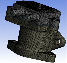
The model TE603, a type of negative pressure valve EGR, was taken as an example. The three-dimensional solid model was established by using 3D drawing software UG. As the valve body structure is relatively complex, several transition angles, certain chamferings and characteristics of some small size structures of the model were simplified under the condition of ensuring the accuracy of relevant physical parameters. The 3D solid model is shown in Fig. 1. The unstructured tetrahedral mesh in the ICEM mesh tool in ANSYS14.0 was applied to mesh the 3D solid model of valve body of EGR, high temperature gas and cooling water gallery. Before meshing, the fluid import and export, solid wall, fluid wall and fluid solid coupling interface were named [8]. There are Node 318209 nodes and Element 1644523 units in the whole model. Fig. 2 illustrates grid graph of the finite element model. When meshing was completed, calculations for solutions could be conducted in ANSYS CFX14.0.
Fig. 1Three-dimensional model of EGR
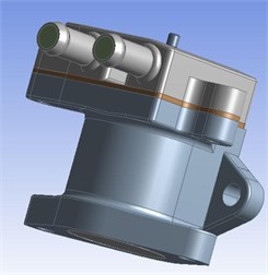
Fig. 2Grid partition results of EGR
3.3. Boundary condition settings of flow and heat transfer
In general, the working condition of EGR valve is adverse. The temperature of gas passing through could reach a maximum of 700 °C and the intake pressure difference is usually in the range of 30 kPa-40 kPa (gage pressure). In this paper, the simulation analysis focuses on the typical working condition when the valve is in the maximum lift. In the CFX software, the inlet boundary condition is set as the velocity entrance and the distribution of velocity in the entrance is assumed to be uniform. Besides, the gravity of the fluid medium is ignored. The specific boundary conditions are set in two cases: with cooling water and without cooling water. In the first case, the fluid velocity in the entrance of cooling water gallery is set to 1.5 m/s, the temperature is 90 °C; the fluid medium is water; the entrance velocity of high temperature gas is 405 m/s, the temperature is 700 °C, the fluid medium is air. The turbulent intensity in both two entrances is set to 5 %. The pressure-outlet boundary conditions are used for the outlet, and the relative pressure is 0 MPa. The way for define turbulence is the same as that for the entrance. Boundary condition settings for the second case are exactly the same without considering cooling water.
When setting the thermal boundary of the coupling heat transfer system of EGR valve, the settings for the boundary surfaces of coupling heat transfer is important. The surfaces between the valve body and cooling water or high temperature as well as the surfaces between the high temperature gas and the valve stem are all considered as the fluid solid coupling conjugate heat transfer surfaces. CFX could be used to calculate the conjugate heat transfer problem and the heat transfer surfaces (the internal wall of the EGR valve and the external surface of the fluid) are the two walls (Wall) which form the contact pair. Therefore, in CFX calculation, the boundary conditions (Boundary Condition) should be adjusted from the wall (Wall) to the interface (Interface). Besides, the interface type (Interface Type) in the domain interface settings (Domain Interface) should be set to the fluid solid coupling interface and the grid connection mode (Mesh Connection) is GGI. In this interface, the thermosetting coupling transfer could be achieved (i.e. heat would be transferred from high temperature gas to the valve body (solid domain) by convection passing through the internal wall of valve body; the valve body is then cooled by such cycle of heat exchange). The heat exchange of the valve body external wall and the environment is achieved by the third kind of thermal boundary conditions (convection). The ambient temperature is set to 50 °C. As the working environmental of engine is in a condition of air cooling, the heat exchange between the external surface of valve body and the air is forced convection in case of which the heat transfer coefficient of air convection is usually considered to be 100 W/(m2·K) in actual engineering.
3.4. Analysis of calculation results of flow and heat transfer
3.4.1. The flow field distribution of the lower valve body
Through numerical simulation, the velocity field and pressure field distribution of the high temperature gas located in the lower valve body are obtained (Fig. 3 and Fig. 4) when the maximum lift of the valve is reached. In order to observe conveniently and clearly, the distribution of the velocity and pressure are observed from the symmetric central plane of the valve which is an auxiliary plane.
Fig. 3Gas velocity field of symmetric central plan
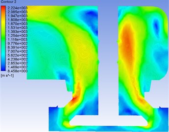
Fig. 4Gas pressure field of symmetric central plan

It can be seen from Fig. 3 that there is no obvious change of velocity when the gas just enters the valve. However, the change of velocity becomes more obvious when passing through the valve seat, furthermore, the speed could reach above 200 m/s in the narrow gap between the valve seat and the wall. After passing through the narrow gap, the air velocity decreases again and a small “island area” could be observed on both upper left and right of the valve seat where velocity values are relatively less than that in surrounding areas. Indeed, in the upper area of “island area” closing to the valve stem, the flow rate of gas increases significantly where the heat exchanges sufficiently resulting in a high temperature of valve stem and valve body in these areas. From another perspective, it can be clearly seen from the pressure field in Fig. 4 that there is no obvious change of pressure when the gas just enters the valve. After passing through the valve seat, the pressure changes largely and the pressure decreases contributing into a considerable pressure difference between the upper and lower parts of the valve seat. The similar phenomenon as in the velocity field could be observed. A small “island area” could be observed on both upper left and right of the valve seat where pressure values are relatively less than that in surrounding areas. Apparently, the velocity is very small in these areas and so as the dynamic pressure resulting in a lower total pressure than in surrounding areas.
3.4.2. The temperature field of coupling system of valve body in initial design (without cooling water gallery)
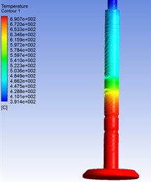
Fig. 5 illustrates the temperature distribution of the symmetric central plan of the valve body coupling system which reflects the temperature distribution of the upper and lower parts of the valve body, the high temperature gas and the valve stem. As per the graph, the temperature of the valve body changes significantly from the minimum of 352 °C to the maximum of 597 °C with a change range of 245 °C. The temperature gradient of the whole valve body is large. The maximum of temperature appears on the contact surface between the lower valve body and the high temperature gas on internal wall with a value of 597.8 °C. In Fig. 6, it can be seen that the temperature ranges from 405 °C to 456.2 °C on the top of the upper valve body where other components are installed. The temperature range is far beyond the temperature requirement on material selection as well as the design of related components. It can also be seen from Fig. 7 and Fig. 8 that the temperature of the upper valve body and valve stem is respectively in contact with the sealing device while the maximum temperature resistance of the sealing device is 180 °C. Therefore, the temperature could not satisfy the temperature requirement on material selection as well as the design of sealing devices.
Fig. 5Temperature field of symmetric central plan
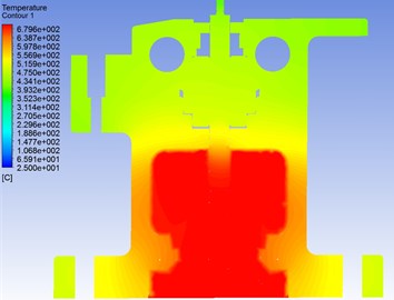
Fig. 6Temperature field of upper valve body
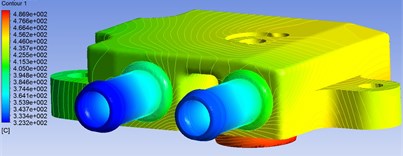
Fig. 7Temperature field of horizontal section
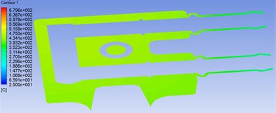
Fig. 8Temperature field of valve stem
The simulation results show that the temperature of the valve body is higher, the heat load is larger, and the temperature distribution is not uniform. The upper part of the upper valve body is installed at other accessories, and the temperature exceeds that of the relevant components and the highest temperature requirement of the design. The temperature of the upper body, the stem and the seal assembly is beyond the working temperature requirement of the sealing material. At the same time, the temperature distribution gradient of the stem is large, and it is easy to cause thermal deformation. Therefore, in order to reduce the highest working temperature of the valve body and stem and improve its thermal load, we need to improve the design of the original EGR valve and add cooling system to the upper valve body.
3.5. Optimization and comparison
3.5.1. Improved design
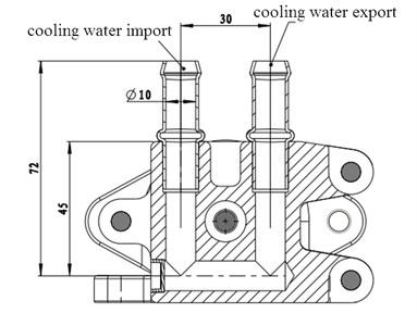
Considering the requirements of the installation accessories and the temperature resistance performance of the sealing components, the design scheme of the original EGR valve is improved. A circular cooling water channel with an inner diameter of 10 mm is designed near the upper valve body to install the seal assembly. The cooling water channel structure is shown in Fig. 9.
Fig. 9Structure of cooling water gallery
3.5.2. Comparative analysis of initial design and improved design
Fig. 10 and Fig. 11 shows the temperature distribution of the upper valve body with and without cooling water respectively while Fig. 10 and Fig. 11 illustrates the temperature distribution of the contact area between the upper valve body and the sealing device with and without cooling water correspondingly. After comparison of Fig. 10 and Fig. 11, it can be seen obviously that the temperature range of the upper valve body with cooling water is from 89.4 °C to 231.6 °C while the temperature range is from 323.2 °C to 486.9 °C without cooling water. Precisely, the maximum temperature with cooling water on the top of the valve body where other components are installed is 160.5 °C comparing with that without cooling water which is 456.2 °C. The temperature ranges from 405 °C to 456.2 °C in this area far beyond the temperature performance requirements of related components. By contrast, after comparing between Fig. 12 and Fig. 13, it can be seen that the temperature range of the upper valve body in contact with the sealing device changes between 143.7 °C and 156.2 °C when without cooling water while the maximum of temperature in the region of the upper valve body reaches 475 °C when without cooling water far beyond the temperature requirements of the seal devices.
Overall, the ideal cooling effect of the valve could be achieved by adding cooling water gallery. Both the temperature of the upper valve body where relative components are installed as well as the temperature of the area in contact with the sealing device meet the working temperature requirement of the sealing devices of EGR valve and other components. To further improve the cooling effect, coolers can be added in the inlet or the outlet of the cooling water gallery.
Fig. 10Temperature of upper valve with cooling water
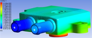
Fig. 11Temperature of upper valve body without cooling water
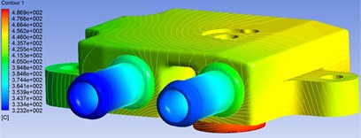
Fig. 12Section temperature of sealing area with cooling water
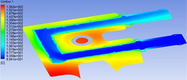
Fig. 13Section temperature of sealing area without cooling water

4. Conclusions
1) Simulation results show that the temperature in areas of the upper body, the stem in contact with seal components is beyond the working temperature requirement of the sealing devices and other components in the case that there is no cooling water gallery in upper valve body;
2) Design of an annular cooling gallery in the upper valve body where sealing device is installed is investigate by simulation analysis in two cases: with and without cooling water. Results show that a better heat dissipation effect of valve body could be found with cooling water and the temperature of the upper valve body meets the working environment temperature requirements of sealing devices and other components;
3) the maximum error of the simulation results is 7 % which indicates that a sufficient accuracy could be achieved in the fluid solid coupling heat transfer simulation.
References
-
Qingguo L., Hongbin L., Zhengbo G. Analysis of fluid solid coupling heat transfer of diesel engine cylinder head. Journal of Ordnance Technology, Vol. 29, Issue 7, 2008, p. 769-773.
-
Zuo C., Liu Y., Cheng X. Effect of EGR ratio on the combustion process of diesel engine with hydrogen enriched EGR. Qiche Gongcheng/Automotive Engineering, Vol. 35, Issue 3, 2013, p. 202-206.
-
Faxue L., Wei A., Wei L. The coupled heat transfer simulation of plate fin EGR cooler. Mechanical Manufacturing and Automation, Vol. 46, Issue 1, 2013, p. 137-140.
-
Guoqing L., Ge S. H., Zhifu Z. H. Fluid solid coupling heat transfer analysis of internal combustion engine considering boiling. Acta Combustion Engine, Vol. 33, Issue 6, 2011, p. 543-548.
-
Jungang G., Liguo H., Chunxia W. Application of fluid solid coupling in transient heat transfer simulation of turbine clades. Mechanical Science and Technology, Vol. 29, Issue 4, 2010, p. 455-460.
-
Ping Zh, Ming W., Guozhong Z. H. Simulation study on heat transfer of buried hot oil pipeline preheating and starting up. System Simulation Technology, Vol. 5, Issue 3, 2009, p. 192-195.
-
Zhichao G., Sin S. H. Simulation analysis of heat transfer and temperature field of high elastic coupling rubber elastic element. Mechanical Design and Research, Vol. 28, Issue 1, 2012, p. 37-41.
-
Zhendong D., Qunji X. Thermodynamic study of friction and wear: current situation and prospect. Chinese Science: Technical Science, Vol. 39, Issue 7, 2009, p. 1211-1215.
About this article

