Abstract
One of the most important challenges exists in using of carbon fiber reinforced polymer(FRP) for strengthening of concrete members is the brittle behavior of RC members due to premature de-bonding of the layers. Mechanically fastened FRP (MF-FRP) systems are emerging as a promising method to prevent de-bonding of FRP strips and the prior brittle failure of strengthened RC members. The approach entails the use of fiber-reinforced polymer connected to the concrete substrate by means of steel anchors. In this research, a new anchor designed to delay de-bonding of FRP in reinforced concrete (RC) strengthened columns. Two reinforced concrete columns strengthened using the externally bonded conventional method and the new proposed method in comparison with unstrengthened RC column in the Laboratory. Specimens subjected to constant axial loading and cyclic lateral loading. Besides, numerical simulations performed using finite element models for nonlinear analyses of RC specimens: un-strengthened column; the column strengthened conventionally EB method and the column using new MF method.
1. Introduction
The columns are considered as the key members of buildings against earthquake. For this reason, to enhance the seismic behavior of the structure, the first and the most important step is to retrofit and improve their columns. FRP have been introduced as one of the new materials in the retrofitting of RC columns in recent decades. However, there are many problems with the use of the FRP in strengthening of concrete members such as the removal of the FRP layers during special loadings. Though, in many cases externally bonded FRP could not meet the desired expectations and might cause a brittle fracture of the composite members. Mechanical anchors could be a good solution to some of these problems. Different systems of connections, such as using bolts or various shapes of steel plates, have been investigated and tested in the literature. For example, some researchers have investigated the use of U-shaped, L-shaped, jackets and steel joints in retrofitting RC members [1-3]. Some using bolts to fix FRP layers to concrete surfaces [4-8]. Also, the use of mechanical joints has been approved as a solution for prevent debonding of the FRP layers [9-14]. Moreover, in wrapping techniques confinement of the concrete with FRP jackets has a significant effect to increase shear strength, axial strength, and ductility of the concrete members, the effectiveness on increasing the column's flexural capacity is limited.
This paper presents an experimental and numerical investigation on the behavior of RC columns strengthened in flexure with MF-FRP layers. First, an experimental program reported and then, a numerical study performed using the finite element methods to develop this new retrofitting method.
2. Experimental program
2.1. Test specimens and materials
Three RC Column Specimens designed and constructed with a height of 1 meter and dimensions 20×20 cm. A 100×30 cm foundation designed to fix the column to the reaction frame and 30×50 cm concrete element used to apply the axial and lateral loadings.
Fig. 1Geometry of the RC columns
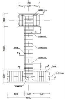
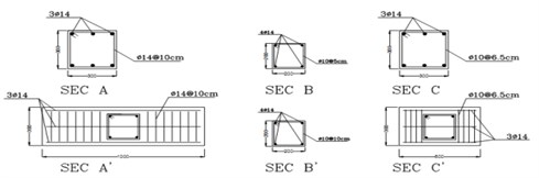
Fig. 2Columns strengthened using FRP
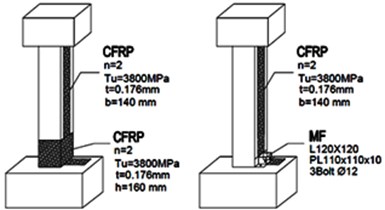
Table 1Mechanical properties of materials
Material | Properties |
Concrete | 22.5 MPa |
Longitudinal reinforcement | 411.6 MPa, 182 GPa |
Transverse reinforcement | 322.4 MPa, 142 GPa |
FRP | 3800, 240 GPa, 1.55 % |
Epoxy Resin | 54, 3 GPa, 2.5 % |
Table 2The characteristics of the Specimens constructed
Specimen | Properties |
C0 | Unstrengthened |
C1 | Strengthened using the longitudinal FRP layers and FRP jackets in plastic zones |
C2 | Strengthened using the longitudinal FRP layers and mechanical fasteners |
2.2. Specimen layout
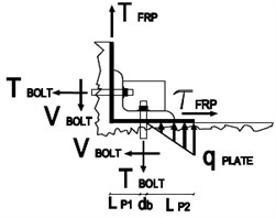
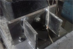
In this research, a new mechanical connection is proposed. The new proposed mechanical connectors fastened the FRP layer to the RC column substrate and was designed using steel angles and bolts. Designing the MF connections was based on initial forces developing in the members during the loading. Fig. 3 shows the initial forces was used in design approach.
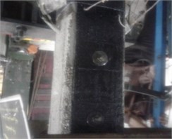
In the laboratory, First the surface of the RC columns prepared and the same layer of longitudinal FRP used on two opposite sides of the RC columns. In C1 column FRP jackets and in C2 column MF used to fix the FRP layers to the RC column. After the FRP system was allowed to cure for about 24 hours the anchorage system assembled. For retrofitting the C2 column first three holes spaced 30 centimeters drilled along the column and the bolts placed in these holes and fixed with two nuts in both sides. An angle with two stiffeners designed and constructed for each side of the RC column. Fig. 3 shows the details of MF systems were used in strengthened C2 column.
Fig. 3Mechanical fasteners used in C2 column
The steps for implementing the mechanical connection included:
1) The locations of bolts were first marked on the surface of the concrete.
2) Holes to the depth of 15cm were drilled at the column-foundation connection.
3) Hardeners welded to the angles and the angles placed in pre-defined positions.
4) Bolts placed in the holes and the holes filled with epoxy adhesive.
2.3. Test setup and loading
The test setup consisted of reaction frame supporting lateral and vertical hydraulic actuators. so, all columns tested under combined axial and lateral loads. Preceding the application of the lateral load, RC columns first loaded with constant axial load using a hydraulic jack at top. The 200 kN axial load applied primarily is approximately 25 % of the ultimate axial load capacity. After initial axial loading, lateral load applied in a displacement control mode.
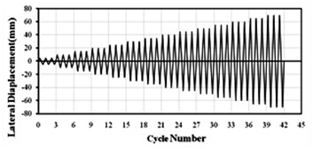
The applied displacement amplitude was a fraction of the estimated tip yield displacement of the C0 column, (~10 mm) reached from the numerical simulation. The lateral cyclic displacement level selected as multiples of 0.5 and three cycles applied at each displacement level. Fig. 4 shows the details of the loading system and the loading protocol applied similarly to all the specimens.
Fig. 4Test setup details and loading protocol
3. Experimental results
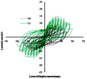
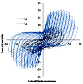
The failure of the tested specimens displayed in Fig. 5. As shown, using the proposed mechanical connection prevented de-bonding of FRP layers and improved column-to-foundation connection. The lateral load-displacement hysteresis curve of column C1 and C2 shown in Fig. 6 in comparison with C0.
Fig. 5Failure mode of C0, C1 and C2
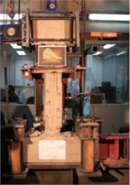
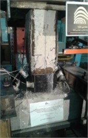
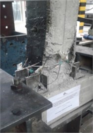
Fig. 6Hysteresis curves of Column C1 and C2 in comparison with C0
4. Numerical investigation
The study of the behavior of composite structures due to their non-homogeneous and nonlinear behaviors is very difficult. Therefore, to carry out such a sophisticated survey, the use of comprehensive numerical analysis programs with high capabilities is required. In this research, the finite element method is used for modeling. The simplifying assumptions used for the numerical model are as below:
• The shear deformation within the adhesive neglected since the adhesive layer is very thin.
• The FRP layer has a linear elastic stress-strain relationship to failure.
In addition, 8-node solid element (Type C3D8) used in concrete three-dimensional modeling. The truss elements carry only axial forces used in reinforcement model and the four-node shell element (S4) has been used to model FRP layers.
4.1. Properties of materials
4.1.1. Concrete and steel
Nonlinear damaged plasticity model for inelastic behavior of concrete assumed and concrete isotropic damage plasticity model is designed and used in nonlinear analysis of the concrete columns. The continuum, plasticity based, damaged model used for concrete modeling. Damage plasticity assumed to characterize the compressive and tensile response of concrete as shown in Fig. 7. At the beginning, the stress-strain relationship is linearly elastic under axial tension until the value of the failure stress reached. Failure stresses in concrete block converted to replace micro cracks in it. Beyond the state of the failure stress in concrete, stress-strain response designed by softening characteristic. Under compression, the response is linear until the value of initial yield . After attaining the ultimate stress in the plastic zone, the response of concrete characterized by the stress hardening followed by strain softening. Therefore, concrete stresses determined unloading from any point on the strain are [11]:
where is the modulus of elasticity of concrete. Then, the effective tensile and compressive cohesion stresses of concrete were estimated as:
Linear Kinematic hardening model which is a bilinear model for steel was assumed for rebar and stirrup.
Fig. 7Concrete damage plasticity model [11]
![Concrete damage plasticity model [11]](https://static-01.extrica.com/articles/18990/18990-img13.jpg)
a) Tension behavior associated with tension stiffening
![Concrete damage plasticity model [11]](https://static-01.extrica.com/articles/18990/18990-img14.jpg)
b) Compressive behavior associated with compression hardening
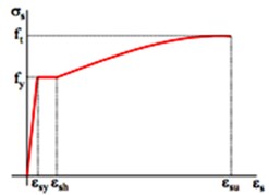
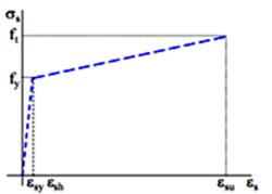
Fig. 8Alternative stress-strain laws for steel reinforcing bars: a) accurate, b) simplified
a)
b)
4.1.2. Carbon fiber reinforced polymer (CFRP)
FRPs are materials with different characteristics in each direction. CFRP were supposed to have linear elastic behavior up to failure. The rupture strain of CFRP is 1.55%.
5. Finite element modeling
To study and evaluate the effect of the proposed detail on the overall behavior of reinforced concrete columns, three columns modeled in a FEM software and nonlinear analysis have been done. Similar to the Laboratory tests constant axial load and the lateral displacement has been applied to the cap beam. The following Numerical models considered:
• not-retrofitted column.
• retrofitted column with longitudinal CFRP layers and CFRP jacketing at both ends.
• retrofitted column with longitudinal CFRP layers and proposed mechanical connection.
5.1. Evaluation of behavior of not-retrofitted column
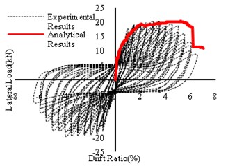
In the first numerical model, the concrete column was considered without any retrofitting. This column is similar to the Laboratory specimen and used as the benchmark model. Fig. 9 shows the finite element and lateral load-displacement diagram from the finite element analysis along with the experimental results.
Fig. 9Finite element model of C0 specimen and lateral load-displacement diagram

5.2. Evaluation of behavior of EB-FRP strengthened column
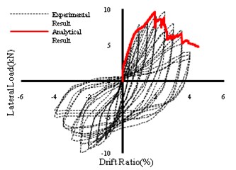
In this model, the concrete column was retrofitted with longitudinal layers of FRP. Based on the fact that the longitudinal layers of the FRP can be restrained by FRP jacketing, FRP wrapping was used at the bottom and top of the column. The height of the wrapping was 16 cm according to the plastic hinge length. Table 2 shows the characteristics of the used polymeric fibers. The lateral load-displacement curve and finite element model of this column shown in Fig. 10.
Fig. 10Finite element model of C1 specimen and lateral load-displacement diagram

Although numerical modeling indicates an increase in the flexural strength of the column reinforced with longitudinal FRP and wrapping in both ends, the results illustrate that with de-bonding of FRP at first cycles of lateral loading the stiffness and overall behavior changed, and the strengthened column could not reach the preferred resistance. Moreover, with de-bonding the FRP layers both RC column and FRP layers resist load individually and could not improve the desired composite action.
5.3. CFRP-strengthened column with proposed mechanical connection
In this section, a new detail proposed for fixing CFRP at the column-to-foundation connection and column substrate. The L Profile St37 Angle used in the proposed mechanical connection. The angle has a tensile strength of 2400 kg/cm2 and a final stress of 3600 kg/cm2 and the modulus of elasticity is equal to 2.1×10⁶ kg/cm2, according to the material tests. In Fig. 11, the finite element model of the column is shown.
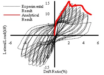
As seen in the results, the proposed retrofitting detail changed the failure mode and increased the bending capacity and lateral displacement of strengthened column. The computational results show that the fracture did not occur in the linear section of the curve as de-bonding of FRP layers did not occur during the loading and the uniform load-displacement curve indicates the ideal composite behavior for this specimen. Therefore, based on the results new proposed mechanical connection had an effective role in overall seismic behavior of retrofitted column.
Fig. 11Finite element model of C2 specimen and lateral load-displacement diagram

5.4. Numerical modeling and experimental results
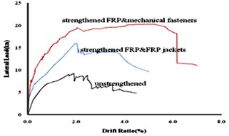
By observing the results obtained from the finite element analysis and comparing them with the experimental results, close proximity is obtained. The ultimate lateral load and lateral drift obtained from the finite element analysis and the experimental tests compared in Table 3. Also, Fig. 12 shows lateral load-displacement curves of all specimens. By comparing the capacity curves of the columns C0, C1 and C2, the inadequacy of traditional methods in retrofitting of concrete columns is determined. Results indicate that the new proposed anchorage system improved the overall lateral strength in comparison with the similar column strengthened with traditional externally bonded system.
According to Fig. 12 the combination of longitudinal FRP and anchorage system displayed the best response characteristics. Using anchorage system improved the overall flexural capacity and the lateral displacement of FRP-strengthened RC column. But the most important point is the ductile failure of the strengthened RC column due to the anchorage system.
Table 3Experimental and numerical results
Specimen ID | Experimental | Numerical | Error | |||
(kN) | (mm) | (kN) | (mm) | |||
C0 | 9.50 | 33 | 9.25 | 2.7 | 2.6 % | 18.2 % |
C1 | 14.64 | 38 | 15.20 | 3.9 | 3.8 % | 2.6 % |
C2 | 20.15 | 55 | 19.92 | 6.1 | 1.1 % | 1.2 % |
As can be seen, the value of the ultimate lateral strength of C1 column increased 64 % compared to the non-reinforced column, but the ultimate lateral drift does not change significantly in this column. The ultimate lateral drift is 2.7 % in column C0 while it is 3.9 % in the C1 column. Besides, as shown in Fig. 12 the stiffness of the C1 column at the beginning of the linear section has increased due to FRP layers. However, after separating the layers from the concrete surface, the linear section of the capacity curves for C1 and C0 column extend in parallel. Based on the results, the C2 column had a better performance than the other specimens. The ultimate lateral strength and the ultimate lateral drift have been significantly enhanced and the capacity of the column has increased. The C2 column has experienced a final resistance of 19.92 kN, which was nearly double that of the control specimen. On the other hand, the ultimate drift has increased to 61 mm in this specimen. So according to the mentioned points, it seems that the flexural retrofitting of concrete columns with the conventional methods do not satisfy the seismic retrofitting criteria.
Fig. 12Lateral load-drift curves
6. Conclusions
Finite element models were developed to simulate the flexural behavior of RC columns externally strengthened by mechanically fastened FRP. Numerical analyses were carried out and validated using experimental results. From the experimental-numerical comparisons, the following considerations were drawn:
1) The finite element procedure yields predictions that are in good agreement with the experimental results when using the accurate non-linear material models. In addition, reasonable results obtained when using the simplified (bilinear) model for steel, making it suitable for design purposes.
2) Experimental tests and numerical modeling demonstrate the efficiency of the proposed anchorage system to strengthen the RC columns. The overall structural behavior is very satisfying, exhibiting a ductile deformation up to failure as the anchorage system changed the overall behavior of the FRP-strengthened RC columns to a composite one.
3) 37 % increase in the ultimate lateral load and 58 % in the ultimate displacement for the MF-FRP strengthened RC column in comparison with traditional EB-FRP strengthened column prove the efficiency of proposed MF detail.
References
-
Wang Y. C., Hsu K. Design recommendations for the strengthening of reinforced concrete beams with externally bonded composite plates. Composite Structures, Vol. 88, 2009, p. 323-332.
-
Jumaat M. Z., Alam A. Experimental and numerical analysis of end anchored steel plate and CFRP laminate flexurally strengthened reinforced concrete beams. International Journal of the Physical Sciences, Vol. 5, Issue 2, 2010, p. 132-144.
-
Ceroni F. Experimental performances of RC beams strengthened with FRP material. Construction and Building Materials, Vol. 24, 2010, p. 1547-1559.
-
Bischof P., Suter R., Chatzi E., Lestuzzi P. On the use of CFRP for the seismic retrofitting of masonry walls and the influence of mechanical anchorage. Polymers, Vol. 6, 2014, p. 1972-1998.
-
Ceroni F., Pecce M., Matthys S., Taerwe L. Debonding strength and anchorage devices for reinforced concrete elements strengthened with FRP sheets. Composites Part B: Engineering, Vol. 39, Issue 3, 2008, p. 429-441.
-
Aram M. R., Czaderski C., Motavalli M. Debonding failure modes of flexural FRP-strengthened RC beams. Composites Part B: Engineering, Vol. 39, 2008, p. 826-841.
-
Napoli A., Matta F., Martinelli E., Nanni A., Realfonzo R. Modelling and verification of response of RC slabs strengthened in flexure with mechanically fastened FRP laminates. Magazine of Concrete Research, Vol. 62, 2010, p. 593-605.
-
Martinelli E., Napoli A., Nunziata R., Realfonzo R. RC beams strengthened with mechanically fastened composites: experimental results and numerical modeling. Polymers, Vol. 6, 2014, p. 613-633.
-
Lamanna A. J., Bank L. C., Scott D. W. Flexural strengthening of reinforced concrete beams using fasteners and fiber-reinforced polymer strips. Structural Journal, Vol. 98, Issue 3, 2001, p. 368-376.
-
Lamanna A. J., Bank L. C., Scott D. W. Flexural strengthening of reinforced concrete beams by mechanically attaching fiber-reinforced polymer strips. Journal of Composites for Construction, Vol. 8, 2004, p. 203-210.
-
Grelle S., Sneed L. Review of anchorage systems for externally bonded FRP laminates. International Journal of Concrete Structures and Materials, Vol. 7, 2013, p. 17-33.
-
Kalfat R., Al Mahaidi R., Smith S. Anchorage devices used to improve the performance of reinforced concrete beams retrofitted with FRP composites: state-of-the-art review. Journal of Composites for Construction, Vol. 17, 2013, p. 14-33.
-
El Maaddawy T. Mechanically fastened composites for retrofitting corrosion-damaged reinforced-concrete beams: experimental investigation. Journal of Composites for Construction, Vol. 18, Issue 2 2014, https://doi.org/10.1061/(ASCE)CC.1943-5614.0000447.
-
Loring H. B., Davids W. G. Mechanically fastened hybrid composite strips for flexural strengthening of concrete beams. Construction and Building Materials, Vol. 76, 2015, p. 118-129.
About this article

