Abstract
The torus involute gear can compensate large axial misalignments and may possess good meshing characteristics without lead correction. In order to study its dynamic characteristics and verify its feasibility of the practical application, a new efficient rigid-elastic coupling dynamic model of multi-tooth is established which includes effects of lubrication oil film and tooth deformations directly in contact simulation of gears. In this model, each tooth is connected with the gearwheel by a rotatable spring-damper element whose stiffness is calculated through analysis of tooth deformation. The normal tooth contact force is determined via Lankarani and Nikravesh model. Variation of contact stiffness and rotatable spring stiffness with contact points are both taken into account. Combined with tooth contact analysis, the computation of friction coefficient is implemented with high efficiency by introducing the average lubrication oil film height. A three-dimension multi-body model of a torus involute gear pair is employed and verified by an impact experiment. The simulated results provide useful information about tooth impacts, dynamic transmission error and lubrication conditions like oil film heights and friction coefficients, and show that this type of gear can work with good meshing characteristics. The contributions in this paper lay theoretical basis for the application of the torus involute gear.
1. Introduction
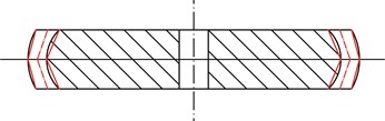
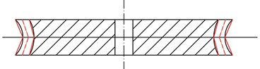
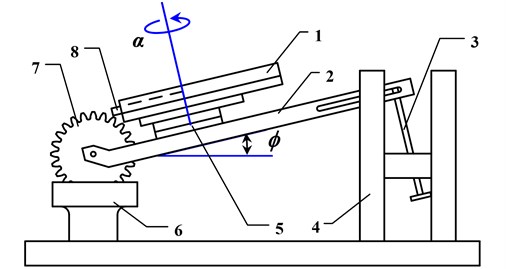
The cylindrical involute gear has the advantages of line-contact meshing, constant working pressure angle, insensitivity to center distance variations and simplicity in use. However, in most cases, transmission performance of line-contact conjugate surfaces is not satisfactory: high sensitivity to machining or mounting error; forced deformation, deviation load and edge contact caused by variation of tooth contact stiffness or bending stiffness. Topological modification technology [1, 2] is usually utilized to produce mismatched meshing of line-contact engaged gears, but actually it is difficult to design and optimize mismatched meshing regions. Mitome [3] invented spherical gears, which geometrically have two types of tooth profiles, convex teeth and concave teeth. Insensitive to machining or mounting error, the spherical gear set allows large axial misalignments without meshing interference. For a spherical gear set, if the spherical center of tip surface or root surface deviates from the gear axis, the gear set can no longer be called a spherical gear set but a torus involute gear set [4]. This type of gear set, easily machined, can also compensate large axial misalignments. As shown in Fig. 1, the tip surface or root surface is respectively an outer or inner torus generated by a circle whose center is not in the gear axis. Each flank of cross-section along face width is still an involute profile generated from the same base circle. For the torus involute gear with convex teeth (hereinafter referred to as convex gear), tooth thickness on the reference circle gradually decreases from the middle to both ends of face width, whereas tooth thickness on the tip circle increases. For the torus involute gear with concave teeth (hereinafter referred to as concave gear), tooth thickness on the reference circle gradually increases from the middle to both ends, while tooth thickness on the tip circle decreases. Although studies on mathematical models and tooth contact analysis have been implemented [5], more sufficient proofs, especially dynamic performance, need to be provided to verify that the torus involute gear (TIG) can work with good meshing characteristics.
As the main excitations of motions along the off-line-of-action (OLOA), friction forces usually couple with backlash and time-varying meshing stiffness to make gear pairs act as nonlinear and time-varying systems. Additionally, power dissipation due to viscous shear of the lubrication oil film along the tooth contact interfaces forms the main source of mesh viscous damping [6]. On the other hand, dynamic meshing forces and slipping velocity fluctuations affect tribological behavior in terms of oil film height, lubrication viscosity and friction forces. Hence it is necessary to understand them together with acting forces and torques, so as to ensure a sufficient transmission lifetime. Currently gear dynamics is usually investigated based on vibration theory [7, 8]. For simplicity, contact for tooth surfaces is modeled through a torsional spring-damper element which acts tangentially to the base circle of each gear. The dynamic mesh impact cannot be calculated accurately in the torsional vibration model. As a numerical approach, the multi-body dynamics method (MBM) could be used to efficiently model contact of gear pairs with acceptable accuracy and considerably less computational effort compared with the finite element method (FEM) [9]. However, meshing friction is usually simplified without considering effects of lubrication oil film in most of multi-body gear models, and contact stiffness is time-independent. Fietkau [10] proposed an efficient transient elastohydrodynamic gear contact simulation method with commercial code Simpack which took into account oil films and elastic deformations directly in the multi-body simulation. But the variation of contact stiffness over mesh is not counted in, and Reynolds equation needs to be solved with the complicated multi-grid method.
In view of tooth shape's complexity of TIG and point-contact pattern, a new efficient multi-body model is in request, which can account for effects of lubrication oil film, tooth deformation and variation of contact stiffness. Therefore, the main motivation of this paper is to build a new multi-tooth dynamics model including transient elastohydrodynamic effects with low computation efforts to understand dynamic characteristics of TIG comprehensively and verify the feasibility of TIG set, which will lay theoretical foundations for the practical application of it.
Fig. 1Torus involute gears
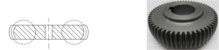
a) Convex gear
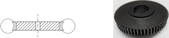
b) Concave gear
2. Multi-tooth dynamics model
An approach of Ebrahimi [9] with circumferentially movable teeth is adopted. Fig. 2 shows a model of meshing multi-tooth. Each rigid tooth has one degree of freedom (DOF): the rotation about the rigid gearwheel center whose angular displacement is . The gearwheel has one rotational DOF with respect to the ground, which is denoted by . All teeth and their respective contacts are treated separately. In order to count in elastic deflection of the tooth, each tooth is connected with the gearwheel by a rotatable spring-damper element. The forces resulted from the flank contact are calculated based on the contact force model including effects of mixed elastohydrodynamic lubrication (EHL).
2.1. Calculation of rotatable spring element stiffness
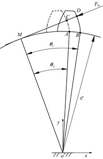
In order to compute the stiffness of a rotatable spring-damper element, its relation with tooth deformation needs to be figured out. As shown in Fig. 3, for simplicity, misalignment of the LOA induced by flank contact deformation is neglected. i.e. contact points only translate along the LOA over meshing.
Fig. 2Dynamic model of meshing multi-tooth
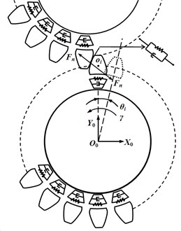
Fig. 3Meshing point translating along LOA
In terms of geometric characteristics of involutes, the stiffness of a rotatable spring-damper element is calculated as:
Fig. 4Approximation of TIGs
a) Convex gear
b) Concave gear
Fig. 5Model for calculating tooth deformation
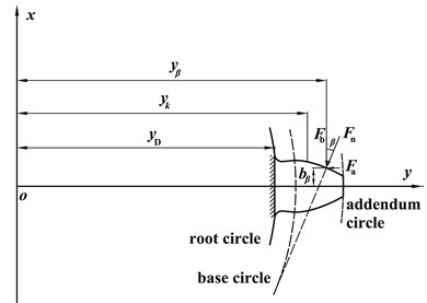
As is known, a gear with continuous linear shifting is called the beveloid gear or conical involute gear. In essence, the TIG is a special spur gear with continuous shifting in the second order. To calculate the tooth deformation, each TIG is approximately viewed as a combination of two conical involute gears as depicted in Fig. 4. In the middle cross-section of a TIG, a coordinate system is established as Fig. 5. Then based on elastic mechanics, the relations between Hertzian contact stiffness , bending stiffness , shear stiffness , axial compressive stiffness , fillet foundation stiffness and Hertzian energy , bending energy , shear energy , axial compressive energy , fillet foundation energy are respectively gained, which are written as:
where:
Stiffness related to the elasticity of root foundation is as follows [11]:
where ; .
The total tooth stiffness is as follows:
Over a mesh cycle the stiffness of a single tooth can be calculated from the effective root to addendum by treating the pressure angle of each contact point as a variable. Then Eq. (1) is employed to give the time-varying stiffness of a rotatable spring-damper element.
2.2. Normal contact modeling
Modeling collision and contact accurately is essential to simulating multi-body systems. The straightforward force-penetration relation proposed by Lankarani and Nikravesh [12], the given Eq. (5), is widely used for mechanical contacts because of its simplicity and easiness in implementation in a computational program and because it is the only model that accounts for the energy dissipation during the impact [13]:
The contact stiffness that depends on material and geometry properties of the contacting surfaces is given as:
where , , , .
The comprehensive curvature radii for meshing points are acquired from tooth contact analysis (TCA). Then contact stiffness that varies with the mesh point is obtained over a mesh cycle.
2.3. Calculation of friction coefficient based on mixed EHL model
As most of gear transmissions work in mixed EHL, the normal contact force load is shared by lubrication oil film and asperity contacts. Similarly, the friction force includes two parts.
2.3.1. Calculation of friction force of lubrication oil film
Friction force of lubrication oil film in mixed EHL is the shear force of lubrication oil film acting in the tangential direction of tooth surface, which includes sliding friction force and rolling friction force. See that sliding friction force is usually much larger than the rolling one, only sliding friction force is considered, which is the sum of shear forces of lubrication oil film acting on tooth surfaces. That is:
To calculate , the non-Newton Ree-Eyring model is employed as follows:
Neglecting the variation of temperature, dynamic viscosity can be approximately represented as follows:
Thus:
On the ground of Hertzian contact theory, when a load is exerted on two contacting bodies, the contact region is approximately regarded as an ellipse, and the average contact stress is calculated by:
According to the studies of Gao [14]and Greenwood [15], the relations between contact area of lubrication oil film and film height ratio can begot by use of regression analysis as follows:
2.3.2. Calculation of friction force in asperity contact
Theoretically, the friction force is sum of shear forces in asperity contacts. Considering friction coefficient for each asperity is approximately constant, we have:
It is generally accepted that asperity contact is in the state of boundary lubrication. The value of is 0.1-0.2 [16]. In this paper, is set to 0.13.
How to reckon the asperity load ratio has drawn much attention in the studies of EHL. The method posed by Jiang [17] is thought to be more applicable to industrial gear drives. Based on numerical and experimental analysis, the formulae of the asperity load ratio and film height ratio were presented as follows:
Finally, the total friction coefficient can be calculated as follows:
It can be seen from the above analysis, , and need to be calculated through TCA. Calculation of friction coefficient may be carried out as the flow chat in Fig. 6.
3. Model verification
As the measurement of contact forces is very difficult or even impossible for many technical problems, so far there is no direct way of measuring dynamic contact forces of teeth. To validate the simulation model, the basic experimental impact investigation is performed using one gear and one simple impact body. For the simplicity of the experimental setup, the investigated gear is not rotating. A cuboid is used as the impact body.
The recoil velocities of the cuboid are indirectly measured using the oscilloscope, and these velocities are compared with simulations. According to the impulse theorem, when there is no friction force, only the gravity force and contact force contribute to the velocity change of the impact cuboid. An assumption can therefore be made that if recoil velocities of the cuboid agree, the contact forces must agree too. The air supplied slide rail is used to guarantee zero friction. As illustrated in Fig. 7, the cuboid translates on an air supplied slide rail in direction of the LOA and collides with a tooth. The slide rail is mounted on a precision rotary stage that allows to adjust the alignment angle . The rotary stage itself is mounted on a frame that allows to adjust the alignment angle . Electrical signals can be acquired to determine the time interval between two successive collisions. So the initial velocity for the subsequent collision is , and its recoil velocity is . The investigated gears have the parameters shown in Table 1. Table 2 demonstrates the measured and simulated results. From this table we note that the simulated results agree well with the measured ones.
Table 1Parameters for a TIG set
Gear 1 | Gear 2 | |
Normal module (mm) | 2.5 | 2.5 |
Pressure angle (deg) | 20 | 20 |
Tooth number | 40 | 49 |
Reference torus radius (mm) | 35 | 55 |
Pitch circle radius (mm) | 50 | 61.25 |
Face width (mm) | 15 | 20 |
Deviation of torus center (mm) | 15 | 116.25 |
Poisson ratio | 0.3 | |
Young’s modulus (N/mm2) | 2.06e5 | |
Table 2Recoil velocity of cuboid
/ mm/s | / mm/s | ||
Measured results | Simulated results | Error / % | |
249.10 | 106.78 | 112.92 | 5.8 |
108.82 | 44.72 | 47.09 | 5.3 |
105.78 | 42.83 | 46.04 | 7.5 |
68.08 | 24.20 | 25.87 | 6.9 |
Fig. 6Flow chat of friction coefficient calculation
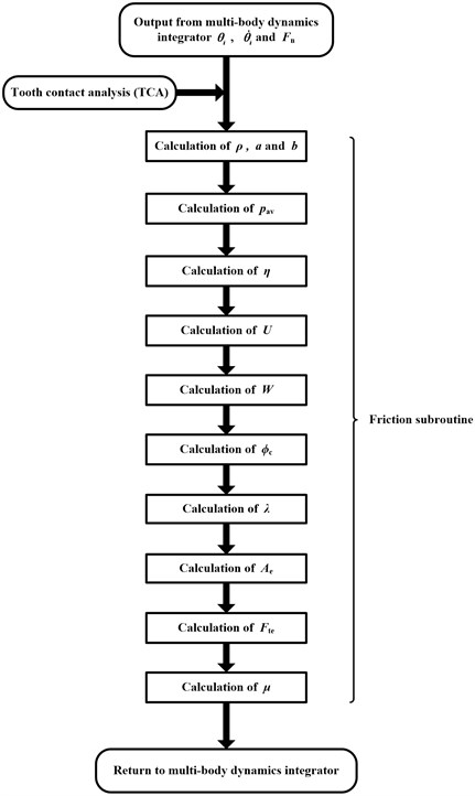
Fig. 7Impact experiment set up (1 – air supplied rail; 2 – inclined bracket; 3 – inclination angle adjustment; 4 – vertical bracket; 5 – rotary stage; 6 – fixture; 7 – TIG; 8 – impact cuboid)
4. Results and discussion
A numerical example of a TIG pair is provided to validate the above approach. From parameters in Table. 1, the tooth surfaces for engaged gears are constructed from the mathematical models, and then 3-D models can be built. Fig. 8 shows the tooth surfaces of engaged TIGs. Then TCA is conducted for each rotating angle of the convex gear (i.e. gear 1) based on theory of differential geometry. As displayed in Table 3, principle curvatures, comprehensive curvature radius, semi-major axis and semi-minor axis are obtained for each contact ellipse. Using Fourier fitting, they can be represented as functions of angular displacement of the gear wheel.
Through polynomial fitting, spring-damper stiffness and contact stiffness can be represented as functions of pressure angles. Fig. 9 displays spring-damper stiffness varying with pressure angle at each contact point, and contact stiffness of the TIG pair is shown in Fig. 10. From above stiffness, the mesh stiffness can be calculated.
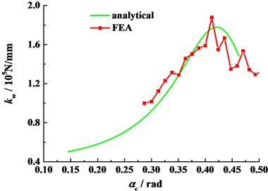
To verify the analytical result of mesh stiffness, an 8-9-tooth finite element model is built as follows (See Fig. 11). The preprocess of the finite element model is completed in Hypermesh; Either of the engaged gears can only rotate about its own axis; Teeth are connected with a central node by massless rigid elements; The driving gear has a certain angular velocity, and a torque 20 N·m is exerted on the other gear. Contact algorithm is explicit surface to surface contact. The dynamic finite element analysis (FEA) is performed in ABAQUS to obtain the comprehensive deformation of TIGs. The mesh stiffness is then computed, and the comparison of two methods is made in Fig. 12.
Fig. 8Tooth surfaces of TIGs
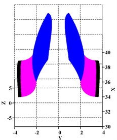
a) Convex gear
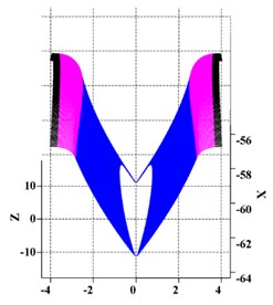
b) Concave gear
Table 3Principal curvatures, comprehensive curvature radii and semi-axes for contact ellipses
(deg) | (mm-1) | (mm-1) | (mm-1) | (mm-1) | (mm) | (mm) | (mm) |
–5.0 | 0.01038 | 0.08964 | –0.00646 | 0.03718 | 1.3670 | 0.1548 | 7.64871 |
–4.0 | 0.01029 | 0.08350 | –0.00642 | 0.03835 | 1.3660 | 0.1573 | 7.95431 |
–3.0 | 0.01020 | 0.07815 | –0.00639 | 0.03960 | 1.3666 | 0.1594 | 8.22639 |
–2.0 | 0.01012 | 0.07344 | –0.00636 | 0.04093 | 1.3681 | 0.1612 | 8.46511 |
–1.0 | 0.01003 | 0.06927 | –0.00632 | 0.04235 | 1.3713 | 0.1627 | 8.67077 |
0.0 | 0.00995 | 0.06555 | –0.00629 | 0.04387 | 1.3758 | 0.1639 | 8.84330 |
1.0 | 0.00987 | 0.06221 | –0.00626 | 0.04551 | 1.3809 | 0.1648 | 8.98255 |
2.0 | 0.00979 | 0.05919 | –0.00623 | 0.04727 | 1.3873 | 0.1654 | 9.08884 |
3.0 | 0.00971 | 0.05645 | –0.00620 | 0.04918 | 1.3950 | 0.1658 | 9.16221 |
4.0 | 0.00964 | 0.05395 | –0.00616 | 0.05125 | 1.4038 | 0.1658 | 9.20234 |
5.0 | 0.00956 | 0.05166 | –0.00613 | 0.05349 | 1.4136 | 0.1657 | 9.20938 |
On the basis of above work, a 3-D multi-rigid-body dynamic model is built in ADAMS as follows. Either of the gearwheels has one rotational DOF with respect to the ground; Each tooth can rotate about its gearwheel center, which is connected with the gearwheel by a rotatable spring-damper element; Contact pairs are defined according to the mating relationship of teeth; The pinion (gear 1) is driven by a constant angular velocity, and a constant torque 20 N·m is simultaneously exerted on the gear (gear 2).
Fig. 9Stiffness of rotatable spring-damper
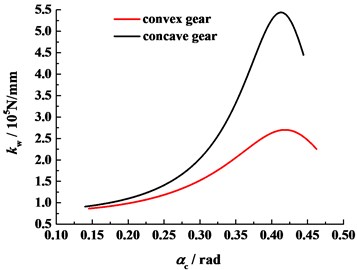
Fig. 10Contact stiffness of TIG pair
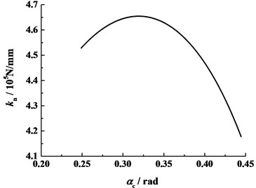
Fig. 11Finite element model of TIG pair
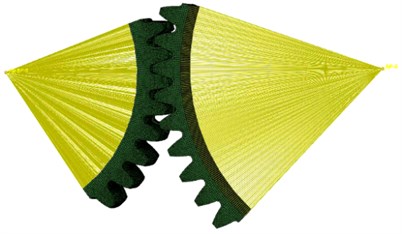
Fig. 12Mesh stiffness of TIG pair
4.1. Dynamic transmission error
Fig. 13 displays the effect of original viscosity on the dynamic transmission error (DTE). Although variation of original viscosity changes friction coefficient, the DTE is observed to vary slightly, which means that the friction force has little effect on DTE. Besides, it can be seen from this figure that transmission precision of the gear set is high because the TIG originates from conventional involute gears. Fig. 14 shows the effect of angular velocity on the DTE. It is noteworthy that the magnitude of DTE does not always rise with the increasing angular velocity. When the angular velocity is more than 600 r/min, the magnitude of DTE rises as it increases. In general, the angular velocity has greater effect on the DTE than the original viscosity.
4.2. Contact force
Fig. 15 shows the normal forces for 3 successive meshing tooth pairs. From this figure the transmission continuity of the gear set can be checked. The duration for double pair meshing over one mesh cycle is and the mesh cycle period is So the contact ratio which shows that transmission continuity is achieved. Moreover, it can also be seen from Fig. 15 that the normal contact force is nearly independent of lubrication viscosity when considering effects of EHL.
Fig. 16 is the result obtained by superposing the normal contact forces of all tooth pairs. The magnitude of normal contact forces can be verified preliminarily. Utilizing the conventional gear design approach, the normal contact force is 347.49 N, and the average value of our model is 353.35 N. The increase in average normal contact force is induced by the effect of impacts during meshing in and out as well as friction forces. Besides, Fig. 16 indicates that when the preceding tooth pair meshes out, at the pitch or the subsequent one meshes in, there exists a major fluctuation of normal contact force.
Fig. 13DTE for different original viscosity (n= 60 r/min)
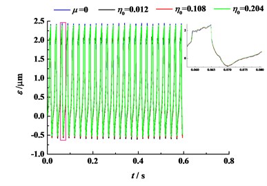
Fig. 14DTE for different angular velocity
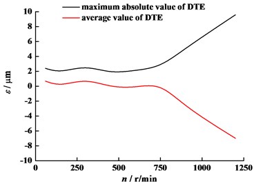
Fig. 15Normal contact force of Tooth pair 3-5 (n= 60 r/min)
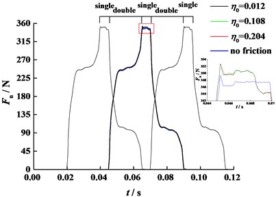
Fig. 16Total normal contact force (η0= 0.012 Pa·s, n= 60 r/min)
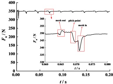
Fig. 17Friction force of 4th tooth pair (η0= 0.012 Pa·s, n= 60 r/min)
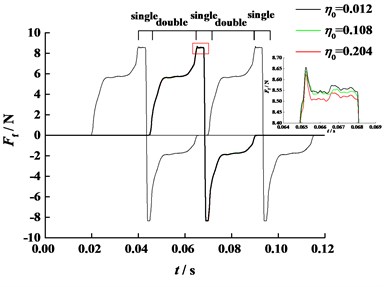
Fig. 18Friction force of 4th tooth pair (η0= 0.012 Pa·s)
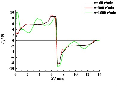
Fig. 17 displays the friction force of the 4th tooth pair for different original viscosity (The friction force of the 3rd pair and the 5th pair are also plotted in black thin line). As depicted in Fig. 17, at the pitch point the relative slip velocity between tooth flanks changes its sign and therefore the friction force does as well. As a result, the normal contact force tends to decline (See Fig. 16). Moreover, original viscosity slightly affects the friction force. The friction force rises with the falling original viscosity because the asperity contact force rises.
Fig. 18 displays the friction force of 4th tooth pair along LOA for different angular velocity. It can be seen from Fig. 18 that the angular velocity has great effect on friction forces. As angular velocity rises, the relative slipping velocity and entraining velocity of engaged flanks increase, and consequently the fluctuation and peak value of friction force tend to increase. However, the general tendency of all plots are similar.
Frequency-domain analysis for normal contact force and angular acceleration of the driven gear are shown in Fig. 19. From the figures the primary resonances are both found at 40.05 Hz, nearly equal to gear mesh frequency ( where is the tooth number for gear 1, and is the rotational speed for gear 1), which is associated with a mode having the LOA transverse motions and the torsional motions of the wheels.
Fig. 19Results in frequency domain (η0= 0.012 Pa·s, n= 60 r/min)
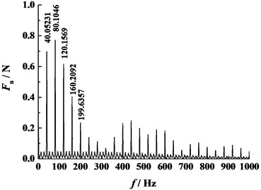
a) Normal contact force
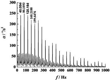
b) Angular acceleration of the driven gear
4.3. Lubrication oil film height
Fig. 20 displays the average lubrication oil film height of the 4th tooth pair for different original viscosity (Those of the 3rd pair and the 5th pair are also plotted in black thin line). As shown in Fig. 20, original viscosity affects the lubrication oil film height markedly. With the increasing of original viscosity, the average lubrication oil film height increases. For a generic tooth pair, as the normal contact force rises, it begins to mesh in, and the average lubrication oil film height declines gradually due to the increasing normal contact force. When the subsequent tooth mesh in, the contact normal force decreases, and therefore the average lubrication oil film height rises.
Fig. 20Average lubrication oil film height of 4th tooth pair (n= 60 r/min)
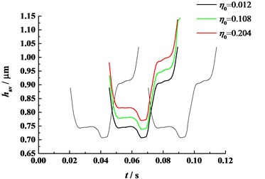
Fig. 21Average lubrication oil film height of 4th tooth pair (η0= 0.012 Pa·s)
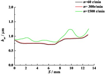
Fig. 21 illustrates the average lubrication oil film height for different angular velocity. As depicted in Fig. 21, angular velocity influences the lubrication oil film height evidently. Obviously, the increasing of angular velocity causes the entraining velocity of engaged flanks to increase. As a result, the average lubrication oil film height tends to rise and fluctuate clearly. All in all, either angular velocity or original viscosity affects lubrication oil film height more strongly than it does to contact forces.
5. Conclusions
A new efficient model for gear contact simulation in mixed EHL is presented and integrated in multi-body simulation environment. Lubrication oil film height and tooth deformations are directly counted in this model. Time-varying contact stiffness and rotatable spring stiffness are both taken into account. Combined with TCA, the computation of friction coefficient is implemented with high efficiency. Subroutines for the computation of normal tooth contact forces and friction coefficient are developed and called by the numerical integrator in commercial code ADAMS. A 3-D multi-body model of a TIG set is employed and verified by an impact experiment. The results indicate that the continuity and precision of transmission can be guaranteed using this type of gear set. Important values like dynamic transmission error, normal and tangential contact forces and average film heights are calculated with high efficiency for different conditions, which lay foundations for application of TIG. Besides, it is feasible to analyze the tribo-dynamic behavior of other point-contact gears using the approach in this paper.
References
-
Li G. L., Li X. G., Liu F., Sun M. H. Method of profile optimization of a form grinding wheel for grinding with additional radial motion of topologically modified gear. Chinese Journal of Mechanical Engineering, Vol. 47, Issue 11, 2011, p. 155-162, (in Chinese).
-
Shih Yi-Pei A novel ease-off flank modification methodology for spiral bevel and hypoid gears. Mechanism and Machine Theory, Vol. 45, Issue 8, 2010, p. 1108-1124.
-
Mitome K., Okuda T., Ohmachi T., Yamazaki T. Develop of a new hobbing of spherical gear. Journal of JSME, Vol. 66, 2000, p. 1975-1980.
-
Liu Lei., Huang Y. H., Tian Z. J., Shen L. D., Liu Z. D. A Type of Concave or Convex Torus Involute Gear and Its Design and Manufacture Method. Chinese Patent No. 201210081587.4.
-
Cao T., Liu Lei Study on tooth surface generation and geometrical characteristics of novel torus-involute gears. China Mechanical Engineering, Vol. 25, Issue 22, 2014, p. 2983-2991, (in Chinese).
-
Li S., Kahraman A. A spur gear mesh interface damping model based on elastohydrodynamic contact behavior. International Journal of Powertrains, Vol. 1, Issue 1, 2011, p. 4-21.
-
Mohammed Omar D., Matti Rantatalo, Olov Aidanpää-Jan Dynamic modelling of a one-stage spur gear system and vibration-based tooth crack detection analysis. Mechanical Systems and Signal Processing, Vol. 55, Issue 3, 2015, p. 293-305.
-
Li H. B., Gao H. C., Zhang Y, Jin D. Q. Nonlinear vibration of hypoid gear with backlash. Journal of Vibroengineering, Vol. 18, Issue 2, 2016, p. 1243-1253.
-
Ebrahimi S., Eberhard P. Rigid-elastic modeling of meshing gear wheels in multi-body systems. Multi-body System Dynamics, Vol. 16, Issue 1, 2006, p. 55-71.
-
Fietkau P., Bertsche B. Efficient simulation of gear contacts including transient elastohydrodynamic effects. Journal of Tribology, Vol. 135, Issue 3, 2013, p. 1-9.
-
Sainsot P., Velex P., Duverger O. Contribution of gear body to tooth deflections-a new bidimensional analytical formula. Journal of Mechanical Design, Vol. 126, Issue 4, 2004, p. 748-752.
-
Lankarani H. M., Nikravesh P. E. Continuous contact force models for impact analysis in multi-body systems. Nonlinear Dynamics, Vol. 5, Issue 2, 1994, p. 193-207.
-
Flores P. J., Claro J. C. P., Ambro’sio Lankarani H. M. Influence of the contact-impact force model on the dynamic response of multi-body systems. Proceedings of the Institution of Mechanical Engineers, Part K: Journal of Multi-body Dynamics, Vol. 220, Issue 3, 2006, p. 21-34.
-
Gao C. K., Qi X. M., Xiong S. B. Study on the lubrication factor of involute spur gears. Chinese Journal of Mechanical Engineering, Vol. 17, Issue 4, 2004, p. 548-551.
-
Greenwood J. A., Williamson J. B. P. Contact of nominally flat surface. Proceedings of Royal Society London, Series A, Vol. 295, 1966, p. 300-319.
-
Wen S. Z. Principles of Tribology. Tsing-hua University Press, Beijing, 1990, (in Chinese).
-
Jiang X., Cheng H. S., Hua D. Y. A theoretical analysis of mixed lubrication by macro-micro approach. Part 1: results in a gear surface contact. Tribology Transactions, Vol. 43, Issue 4, 2000, p. 689 699.
About this article

The authors acknowledge the financial support from the National Natural Science Foundation of China (51205187).
