Abstract
Low-noise, energy-saving and improved sound quality has been the major concern for the eco-design of household appliance product. In this paper, taking off from vibro-acoustic coupling, a composite noise control scheme (CNCS) combined with dynamic vibration absorbing technology, the sound absorption technique, controlling noise in the outlet, and particle damping technique is developed to control the sound radiation from an outdoor unit of a split air-conditioner based on sound sources identification. With the help of developed experiment platform, application effect of each technology and CNCS are measured, experimental evaluation shows that the developed CNCS can reduce the sound pressure level (SPL) more than 10 dB. To clarify the application effect of CNCS in sound quality further, it should be evaluated subjectively by using experiments. Experimental result shows that the stability and smoothness of the unit’s noise have been greatly improved in time domain signal of sound pressure, the fluctuation strength is greatly improved for the controlled unit, the value at the left ear is reduced from 0.0195 vacil to 0.0146 vacil, and the right ear value is 0.0141 vacil instead of 0.0251 vacil. In addition, the sharpness has also been significantly reduced after CNCS, the value at the left ear decreases from 2.11 acum to 1.97 acum, and 2.01 acum to 1.86 acum for the right ear. So, CNCS is a pragmatic technique to control noise, vibration and improving sound quality.
1. Introduction
The development of low-noise and energy-saving air-conditioners has always been the common concern for manufactures. As for the more widely used split air-conditioner, the outdoor unit is more structurally complicated than its indoor counterpart due to the involved complex compressor-pipeline assembly with the exception of the fan assembly. Thus the study of noise control for this unit has always been an important phase in practical design. Over the past decade, many studies have been devoted to this phase of the work [1-10]. Using a topology optimization method Kim et al. [1] obtained the optimum shapes of rubber mount, copper pipe and compressor base plate of a home air-conditioner, and the noise generated by the conditioner was reduced 3 dB when the modified parts were employed. Okutsu [2] calculated the vibration and stress of copper tubes caused by the operation of compressors in air-conditioners. Lee and Kim [3] investigated the most dominant transmission path of a compressor system mounted in the outdoor unit of an air-conditioner by utilizing the vibration power flow approach. Park and Wang [4] conducted a finite element model with all components of the compressor assembly for modal analysis. A block-inserted model between the accumulator and the compressor was successfully developed to reduce the noise level in the target frequency range by using the topology optimization of eigenvalue. Recently, more and more researchers prefer simulating the flow field of the fan assembly in the outdoor unit with the aid of the computational fluid dynamics (CFD) software. Hu and Ding [5, 6] analyzed the influence of the air outlet louver and the deflecting ring on the noise generated by the outdoor unit of by using STAR-CD. It was shown that the circular shape of air outlet louver gave benefit of noise decrease, and the deflecting ring with double contoured duct could improve the aerodynamic performance and reduce the noise generated by the outdoor unit. Jiang et al. [7, 8] developed a prediction method for the flow field and the acoustic field of the outdoor unit based on FLUENT and the modified Fukano’s model. The predicted accuracy of the overall sound pressure level of the outdoor unit was significantly improved. Tian et al. [9] investigated the aerodynamic and aeroacoustic performances of the outdoor unit with two different types of grille based on CFD simulation. Experimental results indicated that the grille affected the flow rate and increased broadband noise level of the outdoor unit. Wei and Shukor [10] analyzed the flow performance of an outdoor unit by changing the fan nozzle radius, depth and other surrounding structures. It was concluded that the inlet radius of the fan nozzle and the fan guard grille were most significant, and the flow field improvements were conducted by minimizing the flow recirculation and separation. The numerical simulation method addressed above can effectively promote the development of new products of air-conditioner, especially in the aspect of the flow field analysis. However, this advanced technique usually depends on the user’s superb skills in the application of software including meshes of grid and selection of suitable mathematical model. More importantly, millions of grid often greatly extend the calculational period. In addition, there are still some academic debates aiming at the accuracy of the predicted noise radiated from the outdoor unit by means of this kind of approach, even though it can better solve the flow field of the outdoor unit.
Above studies indeed marked the achievements and advances in understanding and controlling the noise radiated from the outdoor unit. However, these studies were limited to some local improvements and lacked an overall consideration. Furthermore, the simple noise reduction cannot meet people’s demands for highly comfortable air-conditioners, and the additional subjective sound quality [11] must be taken into consideration. As a matter of fact, the sound quality evaluations of more and more industrial products have been conducted in the past decade [12-13]. As a result, it is desirable to develop an effective composite noise control scheme (CNCS) which can not only reduce the sound pressure level but also improve the sound quality of the outdoor unit of split air-conditioners. To the authors’ knowledge, little work has been conducted to focus on this practical field. This is just the aim of this paper, in which the CNCS has been applied successfully in controlling the noise level from one type of domestic split air-conditioner.
2. Sound sources identification
Noise control methods mainly includes controlling noise source, controlling route of spread and protecting terminal. Given this problem of outdoor units, controlling noise source is the only way. So, sound sources identification will be an important task before determining the noise control scheme.
Fig. 1The considered bare outdoor unit
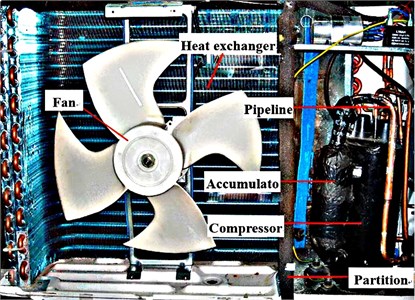
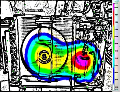
Fig. 2Contour of sound pressure for the unit shot by acoustic camera
2.1. Discern localization of sound sources
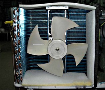
Before determining the noise control scheme, it is crucial to identify the sound source of the unit (as shown in Fig. 1). In this paper, this important work is mainly measured by using the Ring 48 type of Acoustic Camera (made by GFaI tech in Germany) in a semi-anechoic chamber, and the unit operates at the heating mode. The measured result is visualized clearly in Fig. 2, in which one can see that the main sound source of the unit is located at the compressor and the fan assembly.
2.2. Identify acoustic radiation capacity of component
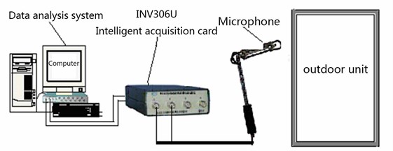
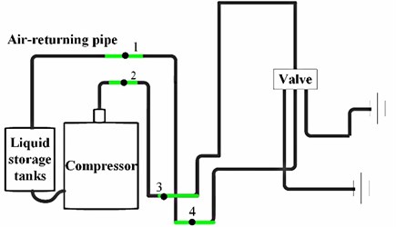
In the previous section, Acoustic Camera easily detected the localization of noise sources. But the noise characteristics is explained in detail, cause parameters of CNCS is not able to be design. So, it is still a difficult problem how to control noise sources efficiently using CNCS. In this section, spectrum sound pressure levels will be investigated further to discover noise characteristic using experiment mothed. The schematic of noise analysis system is shown in Fig. 3. It is consisted of microphone for collecting noise signal, INV306U Intelligent acquisition card to process it and Data analysis system to record the data.
Fig. 3Schematic of noise analysis system
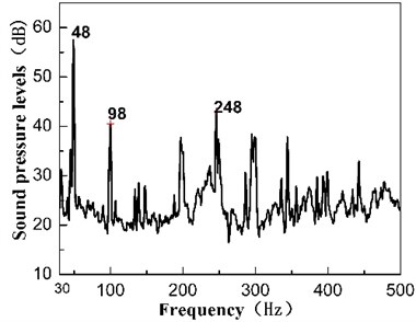
In order to identify acoustic radiation capacity of each component, the experiment test the linear spectrum sound pressure level of outdoor unit in the course of fan operate independently, compressor operate independently and the overall machine operate. The test result is shown in Fig. 4, The numbers in the diagram relate to the frequency of pack, and it show integer multiples of a common fundamental frequency (about 50 Hz). So, 50 Hz will be a critical parameter in suppressing vibration noise radiation.
2.3. Identify vibro-acoustic coupling noise
Thin-wall structure is easy to radiate noise due to the excitation of high velocity flow or acoustic excitation. So, it is necessary to be researched whether vibro-acoustic coupling noise is a major factor or not.
In this section, a semi-numerical approach combining the FEM/BEM and the measurement technique is introduced to simulate the sound radiation. Firstly, a vibro-acoustic coupling model for the unit is developed by using the FEM/BEM software (i.e. ANSYS and SYSNOISE), and then the radiated sound pressure can be easily simulated provided that the excitation inputs are known. As shown in Fig. 5, we consider the compressor and the fan as two independent point sound sources, and regard three compressor mounts on the bottom panel as three identical point vibration sources. Thus, their spectra measured by individual operations are introduced into the developed coupling model as the corresponding excitation inputs. It also should be noted that a virtual point sound sources whose value equals to zero at the junction of the front panel and the bottom panel are considered in order to meet the equivalent requirements for loads. Moreover, the analysis frequency band in simulation is selected as 32-1000 Hz due to the predominant low-frequency acoustical characteristics of the unit.
Fig. 4Linear spectrum sound pressure levels under different operation state
a) Compressor operate independently
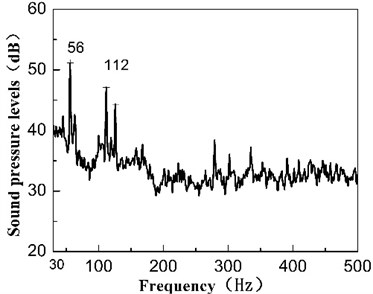
b) Fan operate independently
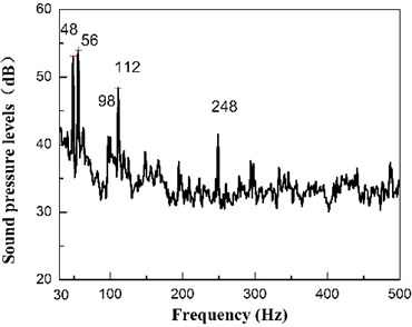
c) Compressor operate independently
Fig. 5Sketch of sound and vibration sources in SYSNOISE
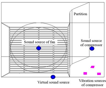
Fig. 6Sound pressure spectra of the unit between simulated results and experimental results
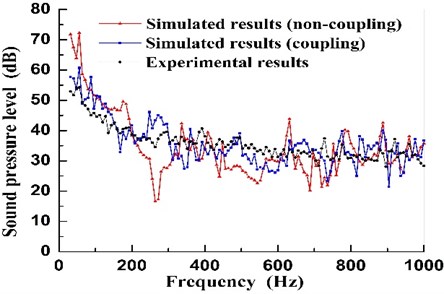
The corresponding numerical simulated results of sound spectra and band sound pressure level (BSPL) are shown respectively in Fig. 6 and Table 1, in which the experimental results are also presented as a comparison. Note that the simulated sound spectra and the corresponding values of BSPL by using the semi-numerical approach when considering the vibro-acoustic coupling between the fluid (air) and the structure (panels) are more close to the experimental results compared to those of the non-coupling case. Some distinct differences are plainly marked between vibro-acoustic coupling and not. So preventing thin-wall structure to radiate noise is a major task of CNCS.
Table 1Comparison of BSPL between numerical and experimental results
Case | A-weighted BSPL (dBA) | BSPL (dB) |
Numerical results (Non-coupling) | 55.6 | 86.3 |
Numerical results (coupling) | 55.0 | 76.4 |
Experimental results | 52.1 | 74.5 |
3. CNCS noise control scheme
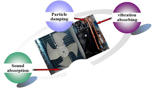
According to this identification result and extensive corresponding experimental tests based on the traditional vibro-acoustic measurement and analysis, a composite noise control scheme (CNCS) involving dynamic vibration absorbing technology, the sound absorption technique, controlling noise in the outlet, and particle damping technique is determined and schematically depicted in Fig. 7.
Fig. 7Sketch of the presented CNCS for the unit
3.1. Dynamic vibration absorbing technology
Dynamic vibration absorber similar to spring-mass-damper system of single freedom. With powerful confrontation forces due to reverse movement of mass relative to foundations, it can suppress foundations vibration effectively. In order to achieve the desired effect, characteristic parameters of dynamic vibration absorber must be optimized. So H-infinity optimization is used for reference in tuning parameters. The amplitude ratio is given [14, 15]:
where, , , , is mass of dynamic vibration absorber, is stiffness of elastic material, is damping of elastic material, is stiffness of foundation, is mass of foundation.
The objective function of infinity optimization will minimize the amplitude ratio. After a series of numerical calculation, better optimal results are achieved. It as follows:
With optimization result, a dynamic vibration absorber with better comprehensive performance that control frequency is about 50 Hz is designed, the diagram as show in Fig. 8(a). The install location is shown in Fig. 8(b), 1 and 2 separately represent two dynamic vibration absorber.
Fig. 8Diagram and distribution of dynamic vibration absorber
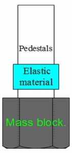
a) Diagram of dynamic vibration absorber
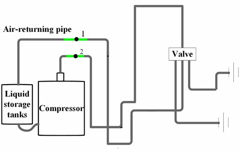
b) Distribution of dynamic vibration absorber
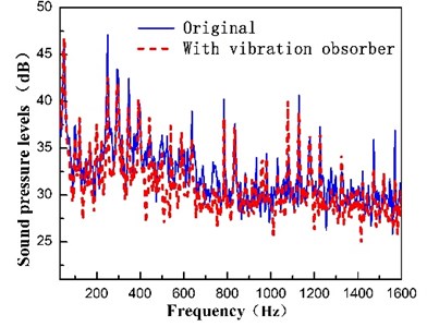
For confirming the application effect of dynamic vibration absorber, the acceleration of location 2 and linear spectrum sound pressure levels is comparing with original. The result is shown in Fig. 9. We can found dynamic vibration absorber achieve fairly effect.
Fig. 9Application effect of dynamic vibration absorber
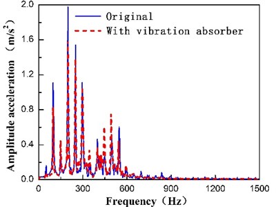
a) Amplitude acceleration of pipe vibration
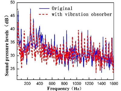
b) Linear spectrum sound pressure levels
3.2. Particle damping technology
Particle damping is a pragmatic passive vibration control technology, it is able to effectively control vibration and noise control due to collision and friction between particles. After many years of research, our team successfully developed a numerical model to predict damping effect of particle damping base on multiphase flow theory of gas-particle. It is described as follows [16-19]:
where is the height of the cavity and is the diameter of the cavity, is the equivalent volume density of the mixture flow, is the restitution coefficient of the particle, is the radial distribution function, and is the density and the mean diameter of particles respectively, is the packing ratio is defined as the volume of particles to the total volume of the cavity, is the second invariant of the deviatoric stress tensor, is the angle of internal friction.
Fig. 10Image and distribution of particle damper
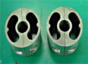
a) Image of particle damper
b) distribution of particle damper
The numerical model could be used to predict damping effect that particle damping be applied in complex continuum structural or to optimize the characteristic parameters of particle damping. In this section, the damping effect of particle damper be improved base on numerical model and application space. The diagram of particle damping and the install location as show in Fig. 10. 1 to 4 separately represent the install location of four particles damper.
To clarify the effect of vibration and noise control further, the acceleration of location 2 and linear spectrum sound pressure levels of outdoor unit with particle damper and without is collected by experiments. The result is shown in Fig. 11. It becomes more evident that Amplitude acceleration of pipe vibration are able to effectively suppress, the noise radiated capacity due to vibration is weakened.
Fig. 11Application effect of dynamic vibration absorber
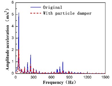
a) Amplitude acceleration of pipe vibration
b) Linear spectrum sound pressure levels
3.3. Sound absorption technology
Acoustic as an excitation source will induce structural vibration and further to radiate regeneration noise. Outdoor unit is no exception; the share of regeneration noise has been discussed in vibro-acoustic coupling analysis. So, preventing vibro-acoustic coupling is an effective measure to control noise and vibration. In this section, the sound absorption technology is adopted to absorb noise on walls and prevent vibro-acoustic coupling. The paste position of the sound-absorbing materials is shown in Fig. 12.
Fig. 12Schematic of Sound absorption technology
With spongia, for example, to evaluate the application effect of sound absorption technology. Fig. 13 show the result (A-weighting sound pressure levels and line-spectrum sound pressure levels) of outdoor unit with sound absorption technology and without. We can found sound absorption technology plays an effective role in preventing vibro-acoustic coupling.
Meanwhile various of sound-absorbing materials is used to prevent vibro-acoustic coupling, the result by experiment is listed in Table 2. Judged by the values, fiber material has higher efficiency in vibro-acoustic coupling.
Fig. 13Spectrum diagram of Sound pressure level
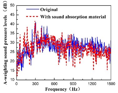
a) A-weighting sound pressure levels
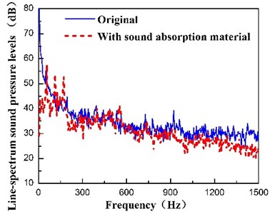
b) Line-spectrum sound pressure levels
Table 2Noise reduction effect with sound absorption material
Case | A-weighting sound pressure levels (dBA) | Line-spectrum sound pressure levels (dB) |
Original | 56.0 | 81.5 |
Fiberglass | 55.4 | 68.5 |
Polyester fiber | 55.5 | 68.0 |
Spongia | 55.4 | 70.0 |
3.4. Controlling noise in the outlet
Furthermore, it is of interest to compare the sound radiation from the unit equipped with two different outlet grilles, i.e. the rectangular grille and the circular grille, respectively. The simulated sound spectra and BSPL obtained by utilizing the presented approach are compared in Fig. 14 and Table 3. It can be found that the sound radiation for the case of circular grille is slightly lower than that of rectangular grille case (original prototype), which is consistent with the conclusion conducted [9].
Table 3Simulated BSPL for the unit with different grilles
Type of grille | A-weighted BSPL (dBA) | BSPL (dB) |
Rectangular grille (original) | 55.0 | 76.4 |
Circular grille | 54.4 | 75.8 |
Fig. 14Sound pressure spectra of the unit for different grilles
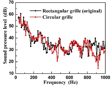
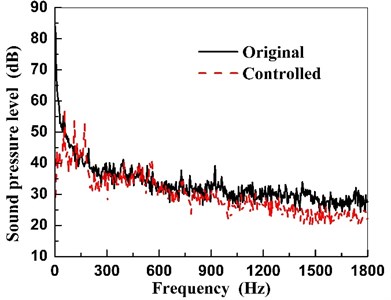
Fig. 15Sound pressure spectra of the unit before and after CNCS
3.5. The analysis of CNCS application effect
After implementing the developed CNCS on a prototype of the unit, an experimental work to evaluate the noise reduction of the prototype is performed by utilizing the traditional acoustical FFT measure system. The comparison results between the original (before CNCS) and controlled (after CNCS) unit are shown in Fig. 15, and are summarized in Table 4. Note that the SPL of the controlled unit decreases more than 10 dB compared to that of the original one. However, the A-weighted SPL changes a little before and after CNCS. This means that the CNCS can effectively control the low-frequency noise of the unit. Moreover, one can obtain the same conclusion from Fig. 15 that the sound pressures decrease significantly within the low-frequency band lower than 500 Hz.
Table 4Overall sound pressure level for the unit before and after CNCS
Case | A-weighted SPL (dBA) | SPL (dB) |
Original | 56.0 | 81.5 |
Controlled | 55.2 | 67.5 |
4. Evaluation of sound quality
The significant noise reduction addressed above does not mean that the controlled unit can be regarded acoustically as a good quality product, and its sound quality should be evaluated subjectively. In this section, four main indicators, i.e. the loudness, the roughness, the fluctuation strength and the sharpness are chosen for evaluating the sound quality for the unit before and after CNCS. This assessment work is performed by the corresponding analysis software inserted in the HMS IV-HEAD Measurement System (see Fig. 16).
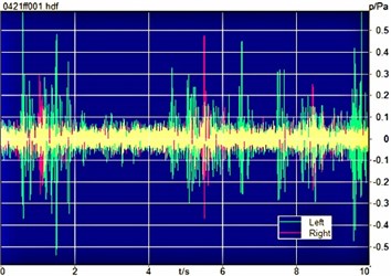
Before evaluating the sound quality, the acquisition of time domain signal of sound pressure is firstly conducted. Fig. 17 shows the time history of sound pressure of the unit before and after CNCS. It can be seen that there are little glitch peaks in the time history of sound pressure of the controlled unit compared to that of the original one.
Fig. 16The HMS IV-HEAD Measurement System in sound quality evaluation testing
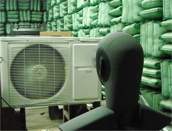
Fig. 17Time history of sound pressure of the unit before and after CNCS
a) Original
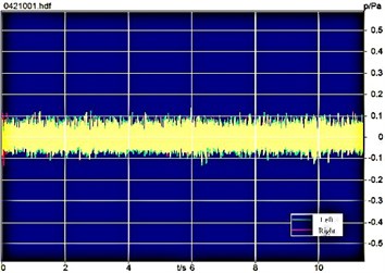
b) Controlled
Fig. 18Loudness spectra of the unit before and after CNCS

a) Original
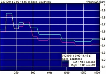
b) Controlled
This may indicate that the stability and smoothness of the unit’s noise have been greatly improved. Subsequently, the sound quality of the unit is evaluated, and the relating evaluation results of four indicators are shown in Figs. 18 to 20, and are summarized in Table 5. It can be observed that the loudness and the roughness change little after CNCS, and the corresponding values at the right ear even slightly increase. However, the fluctuation strength is greatly improved for the controlled unit, the value at the left ear is reduced from 0.0195 vacil to 0.0146 vacil, and the right ear value is 0.0141 vacil instead of 0.0251 vacil. In addition, the sharpness has also been significantly reduced after CNCS, the value at the left ear decreases from 2.11 acum to 1.97 acum, and 2.01 acum to 1.86 acum for the right ear. It can be concluded that the subjective sound quality is also significantly improved by utilizing the CNCS in controlling the noise radiated from the unit while reducing the value of SPL objectively.
Fig. 19Roughness spectra of the unit before and after CNCS
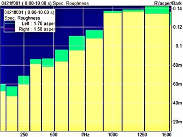
a) Original
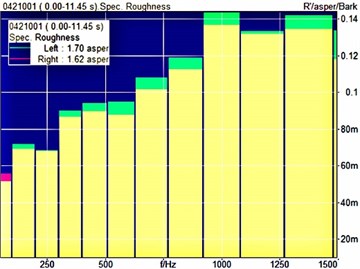
b) Controlled
Fig. 20Fluctuation strength spectra of the unit before and after CNCS
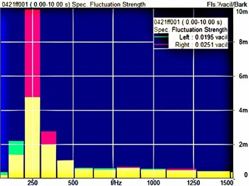
a) Original
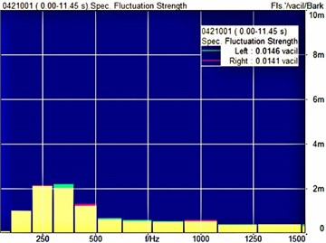
b) Controlled
Table 5Sound quality comparison for the unit before and after CNCS
Sound quality indicator | Left ear | Right ear | ||
Original | Controlled | Original | Controlled | |
Loudness (sone) | 10.9 | 10.8 | 9.41 | 9.83 |
Roughness (asper) | 1.70 | 1.70 | 1.58 | 1.62 |
Fluctuation strength (vacil) | 0.0195 | 0.0146 | 0.0251 | 0.0141 |
Sharpness (acum) | 2.11 | 1.97 | 2.01 | 1.86 |
5. Conclusions
In this paper, a composite noise control scheme (CNCS) involving dynamic vibration absorbing technology, the sound absorption technique, controlling noise in the outlet, and particle damping technique is determined to control noise and vibration of outdoor unit. Experimental results show that the developed CNCS can effectively control the sound radiation from the unit, the sound pressure level (SPL) is reduced more than 10 dB. Meanwhile, the sound quality also be evaluated subjectively by using experiments. Experimental result shows that the stability and smoothness of the unit’s noise have been greatly improved in time domain signal of sound pressure, the fluctuation strength is greatly improved for the controlled unit, the value at the left ear is reduced from 0.0195 vacil to 0.0146 vacil, and the right ear value is 0.0141 vacil instead of 0.0251 vacil. In addition, the sharpness has also been significantly reduced after CNCS, the value at the left ear decreases from 2.11 acum to 1.97 acum, and 2.01 acum to 1.86 acum for the right ear. the developed CNCS can not only effectively control the sound radiation from the unit, but also significantly improve the sound quality of the unit. The developed CNCS can not only effectively control the sound radiation from the unit, but also significantly improve the sound quality of the unit. Further work is still required to make this kind of method a practical design tool.
References
-
Kim S. G., Cho K. L., Cho Y. S., Chang S. K. Reduction of the vibration of a home air-conditioner by finite element analysis and homogenization method. Proceedings of SPIE, Vol. 3089, 1997, p. 1739-1743.
-
Okutsu N. Study on the vibration and stress of copper tubes in refrigerators and air-conditioners. JSME Transactions, Part C, Vol. 63, 1997, p. 2201-2205, (in Japanese).
-
Lee H. J., Kim K. J. Multi-dimensional vibration power flow analysis of compressor system mounted in outdoor unit of an air-conditioner. Journal of Sound and Vibration, Vol. 272, 2004, p. 607-625.
-
Park J. C., Wang S. Y. Noise reduction for compressors by modes control using topology optimization of eigenvalue. Journal of Sound and Vibration, Vol. 315, 2008, p. 836-848.
-
Hu J. W., Ding G. L. Effect of the air outlet louver on the noise generated by the outdoor set of a split-unit air-conditioner. Applied Thermal Engineering, Vol. 26, 2006, p. 1737-1745.
-
Hu J. W., Ding G. L. Effect of deflecting ring on noise generated by outdoor set of a split-unit air-conditioner. International Journal of Refrigeration-revue Internationale du Froid, Vol. 29, 2006, p. 505-513.
-
Jiang C. L., Tian J., Ouyang H., Chen J. P., Chen Z. J. Investigation of air-flow fields and aeroacoustic noise in outdoor unit for split-type air-conditioner. Noise Control Engineering Journal, Vol. 54, 2006, p. 146-156.
-
Jiang C. L., Chen J. P., Chen Z. J., Tian J., Ouyang H., Du Z. H. Experimental and numerical study on aeroacoustic sound of axial flow fan in room air-conditioner. Applied Acoustics, Vol. 68, 2007, p. 458-472.
-
Tian J., Ouyang H., Wu Y. D. Experimental and numerical study on aerodynamic noise of outdoor unit of room air-conditioner with different grilles. International Journal of Refrigeration-revue Internationale du Froid, Vol. 32, 2009, p. 1112-1122.
-
Wei E. P. T., Shukor M. H. A. A study of effects of surrounding structures towards airflow performance in the outdoor unit of split-type air-conditioners, Proceedings of the 6th WSEAS International Conference on Fluid Mechanics, Ningbo, China, 2009, p. 15-21.
-
Blauert J. Product-sound assessments: an enigmatic issue from the point of view of engineering. Proceedings of Inter-noise 94, Yokohama, Japan, 1994, p. 857-862.
-
Bodden M., Heinrichs R., Linow A. Sound quality evaluation of interior vehicle noise using an efficient psychoacoustic method. Proceedings of the Euro Noise 98, Oldenberg, Germany, 1998, p. 609-614.
-
Ih J. G., Lim D. H., Shin S. H., Park Y. Experimental design and assessment of product sound quality: application to a vacuum cleaner. Noise Control Engineering Journal, Vol. 51, 2003, p. 244-252.
-
Ormondroyd J., Den Hartog J. P. The theory of the dynamic vibration absorber. Journal of Applied Mechanics, Vol. 50, 1928, p. 9-22.
-
Cheung Y. L., Wong W. O. H-infinity optimization of avariant design of the dynamic vibration absorber-revisited and new results. Journal of Sound and Vibration, Vol. 330, 2011, p. 3901-3912.
-
Wu C. J., Liao W. H., Wang M. Y. Modeling of granular particle damping using multiphase flow theory of gas-particle. Journal of Vibration and Acoustics, Vol. 126, 2004, p. 196-203.
-
Wu C. J., Yang R. C., D. Q. Wang, Prediction on vibration response of a cantilever particle damping beam based on two-phase flow theory of gas-particle. Chinese Journal of Mechanical Engineering. Vol. 49, 2013, p. 53-61.
-
Wu C. J., Yang R. C., Wang D. Q. An improved model of granular particle damping using multiphase flow theory of gas-particle. 20th International Congress on Sound and Vibration, Bangkok, Thailand, 2013.
-
Wang Dongqiang, Wu Chengjun Vibration response prediction of plate with particle dampers using co-simulation method. Shock and Vibration, 2015, p. 270398.
About this article
