Abstract
Novel rotation air hammer (NRAH) is a rock-breaking tool in the gas drilling. The rock-breaking ability of the NRAH is mainly from the collision between piston and drill bit in it. The collision makes the piston and the drill bit suffer from a high instantaneous impact stress, so that they are prone to failure. Thus, both of them are not only the most crucial parts of the NRAH, but also the easily damaged parts. So it is necessary to analyze the impact stress in them and optimize their structure to improve the security and reliability. First of all, we analyzed the working mechanism of the NRAH to understand motion and structure of the piston and the drill bit. Then we used the LS-DYNA program to analyze impact dynamics problem of the piston and the drill bit to obtain their stress change rule in the impact process. According to the structure optimization, the security coefficient of the piston and the drill bit has been obviously improved. Moreover, their energy conversion regulations were studied in the impact process of the NRAH and the last impacting velocity of the piston was computed, which can provide helpful for effective application of this tool in the field. Finally, based on the experimental study on the NRAH after the optimization, we found that its function had satisfied the design requirements as well as overall performance was improved.
1. Introduction
At present, the gas drilling technology is one of the key technologies in the field of oil and gas exploration and development. This technology can solve a lot of problems which the conventional drilling technologies could not deal with in complex stratum [1-2]. For the gas drilling technology, air hammer is currently one main rock breaking tool [3-4]. The NRAH is a new type air hammer developed by our team based on traditional air hammer, which can be used for the straight well drilling and the directional well and horizontal well drilling [5-6]. In the working process of the NRAH, the piston drove by high pressure gas will fast impact the drill bit, and then the energy the drill bit obtained transmits to the rock to achieve the purpose of broken rock. And yet their velocity including size and direction happen a rapid change in very short impact time [8]. Thus both the piston and the drill bit suffered from the high instantaneous stress that was transmitted quickly in them in the form of stress wave. This phenomenon above seriously restricts the design of their size and greatly reduces component life [9].
However, few researchers have addressed this problem of the contact between the piston and the drill bit of the NRAH, which belongs to the category of impact dynamics. As we all known, the impact force is different from the static pressure. The impact force has a remarkable characteristic that there is a large amplitude change in a short time, for example, the impact force in the NRAH happens a rapid change in the tens of microseconds from zero up to tens of thousands Newton, and after hundreds of microseconds down to zero again [11]. The impact process of the piston and the drill bit is also a complicated dynamic response process with particular dynamic characteristics. So it is usually difficult to adopt the traditional methods to solve this problem [12]. In the field of impact dynamics, LS-DYNA program is one widely used finite element numerical computational software. This software can be used for the problem of geometric nonlinearity, material nonlinearity and interface state nonlinear, particularly suitable for solving the nonlinear dynamic impact problem for various two-dimensional and three-dimensional nonlinear structures [13]. And post- processing module of LS-DYNA can display continuous dynamic development process of analysis objects at any time, such as the display of the stress change rule of drill bits and the piston and the transmission process of impact wave in collision process, and extract data influencing on the research result [14-15].
The purposes of this paper is to obtain their stress change rule in the impact process by analyzing the impact dynamic problem between the piston and the drill bit, to carry on the optimum design of structure for them and to provide guidance for field application of the NRAH. In next section, the working mechanism of the NRAH was analyzed to prepare for the establishment of simulation model. In Section 3, we used LS-DYNA program to analyze the stress change rule of the piston and the drill bit in operating condition, and optimized their structure based on the results of the simulation analysis above. Then the energy conversion of NRAH and last impacting velocity rule of the piston were studied in Section 4. In order to observe the NRAH’s function and drilling effect, we carried out the experimental study of the scene drilling process simulation in Section 5.
2. The working mechanism of the NRAH
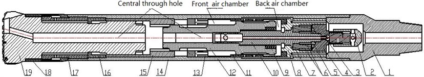
We have designed a novel rotation air hammer NRAH which of structure sketch is shown in Fig. 1. The core of its mechanism is to achieve impact of the piston and the drill bit with gas drive of an air compressor and to transform a linear motion into rotary motion of the drill bit within a limited space.
Fig. 1The structure of the NRAH: 1 – upper sub; 2 – check valve; 3 – orifice plug; 4 – air distributor bonnet; 5 – thrust bearing; 6 – key; 7 – clutch; 8 – air distributor; 9 – adjustable nut; 10 – spiral mandrel; 11 – inner casing; 12 – piston; 13 – guide sleeve; 14 – outer casing; 15 – transmission sleeve; 16 – snap ring; 17 – lower sub; 18 – anti-drop; 19 – drill bit
There are three different processes in one work cycle of the NRAH: return stroke process, impact stroke process and chip removal process.
2.1. Return stroke process
In the process, compressed air injected will get into the Upper Sub 1 to open the Check Valve 2 through a pipe system. It arrives at the Front air chamber from the Air Distributor 7 to front row vent of the Inner Casing 11. Then the Piston 13 makes a return stroke under the pressure differential of the compressed air. Meanwhile, the air in the Back air chamber drains off into the Central through hole via airway between the Spiral Mandrel 9 and the Piston 13, and to reach bottom of the drill bit. When the movement of the upper section of the piston big end (right end) gets to a certain extent, the Front air chamber will close and the air pressure will decrease, then the compressed air prevents the piston to move upward and makes the piston return stroke. With return stroke of the piston continuously, air intake of the Back air chamber is opened to take in air and the piston further returns upward to the top dead center as shown in Fig. 2. When middle part of the piston slides out from the Guide Sleeve 13, air outlet in the Front air chamber turns on, and exhaust air is discharged to the bottom of well through the Central through hole.
Fig. 2Return stroke process
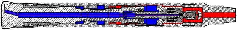
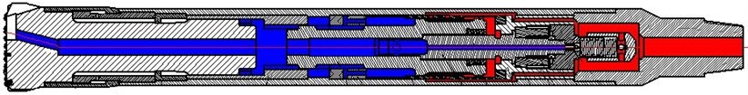
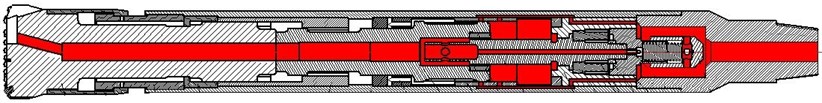
Notes: Red region is air intake area that connected with the air source and also is high pressure zone; Blue region is air outlet area that connected with the bottom annulus space and also is low pressure zone.
2.2. Impact stroke process
The Fig. 3 is the beginning stage of the impact stroke process. The compressed air goes into the Back air chamber from the Air Distributor to back row vent of the Inner Casing. Then the Piston begins a stroke downward and the air in the Front air chamber is discharged to the well bottom. And then by the effect of compressed air in the Back air chamber, the piston continues the impact stroke with a very high speed. When the middle part of the piston slides into the Guide Sleeve, the Front air chamber is closed and the air begins to be compressed, so that movement of the piston is blocked. With the piston stroke continually, the air intake vent of the Front air chamber opens gradually with the air outlet vent in the Back air chamber closing. Then the air gets into the Front chamber via the Inner Casing to slow speed of the piston stroke. But the piston goes on the stroke to downward under expansion force of the air in the Back air chamber. And the air passage will open between the Spiral Mandrel and the piston, and the compressed air in the chamber is discharged to the bottom of the drill bit. Under the obstruction of the compressed air in the Front air chamber, the piston stroke slows until it impact on the drill bit, which is the completion of the impact stroke process.
Fig. 3Impact stroke process
2.3. Chip removal process
In the working process of the NRAH, it is needed to be stopped impacting to perform chip removal process by supplying the compressed air. Because there always are a lot rock slags and sludge mixtures in the bottom of the well when the drill rig ends one work cycle, which will affect rock breaking to decrease the drilling efficiency. In order to ensure the cleanness of the bottom of the well, it is necessary to make all compressed air to get rid of rock slags and sludge mixtures by stopping the return stroke and the impact stroke. The chip removal process of the NRAH is shown in Fig. 4.
Fig. 4Chip removal process
3. Dynamics analysis and structure optimization
3.1. Establishment of simulation model
Based upon the analysis results of the working mechanism of the NRAH above, we established a dynamic simulation model of the piston and the drill bit with the LS-DYNA program [16]. During the modeling process, the SOLID164 unit was adopted to mesh the simulation model, and refining for their contact areas and key parts [17]. The mesh model of the assembly body of the piston and the drill bit was obtained, as shown in Fig. 5. Moreover, the material properties of the piston and the drill bit were set by reference to Table 1.
Fig. 5Mesh model of the piston and the drill bit
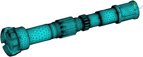
Table 1Material properties of the piston and the drill bit
Part | Material | Elasticity modulus (MPa) | Poisson‘s ratio | Density (Kg/m3) | Tensile Strength (MPa) | Yield strength (MPa) |
Piston | 20CrMnTi | 2.06E5 | 0.3 | 7800 | 1080 | 850 |
Drill bit | 20Ni4Mo | 2.1E5 | 0.27 | 7800 | 1480 | 1220 |
In the most of one cycle of operation, the piston only affect by the compressed air and the impact force suffered from is smaller. But the piston can generate a huge impact force for the drill bit in a very short time when it runs down to impact on the drill bit. This impact force will cause a stress wave to transmit between the piston and the drill bit. Therefore, the piston and the drill bit were defined as the main study objects during this collision process. In order to analyze the whole impact dynamics process of the piston and the drill bit, an initial velocity was set in simulation process and it remained unchanged in the instantaneous impact process, then that will be used to compute last impact velocity of the piston. In the numerical simulation on the impact dynamics of the NRAH, the simulation time was controlled within 500 μs, the whole of head face of the drill bit was full constraint, and last impact velocity of the piston was set to 8.1 m/s.
3.2. Analysis of simulation result
Through the simulating calculation of the LS-DYNA program, we obtained the results of the stress distribution and the transmission status of the stress wave in the piton and drill bit when the impact time was at 100 μs, as shown in Fig. 6. It can be seen from the Fig. 6, stress wave starts to transmit from collision plane to their big-end after collision of the piston and the drill bit, and the largest stress region that value is 555.9 MPa is contact surface of the collision. Moreover, the stress waves has crossed the spline and small end in the piston and reached its middle part at this time, and the stress waves has been reached thin neck part in the drill bit.
In Fig. 7, it displays the stress distribution and stress wave transmission status of the piston and the drill bit at 200 μs. As the stress waves transmitting further, the largest stress regions become small end of the piston and collision zone at this moment, and the maximum stress value is 555.9 MPa. Meanwhile, the stress waves have been transmitted the end face of the big end in the piston and the step face in the drill bit.
When impact time is at 300 μs, the stress distribution and the stress wave transmission status was obtained, as shown in Fig. 8. With the further transmission of the stress waves in them, the largest stress regions are still the collision zone and the small end zone of the piston at 300 μs, but the maximum stress value rises further to 632.8 MPa. Moreover, on the end face of the big end in the piston the stress waves start to weaken, but for the drill bit, the stress waves just arrived at its end face.
Fig. 6Stress distribution and stress wave transmission status at 100 μs
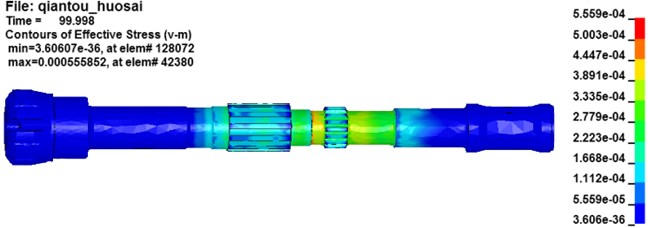
Fig. 7Stress distribution and stress wave transmission status at 200 μs
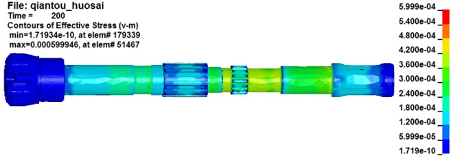
Fig. 8Stress distribution and stress wave transmission status at 300 μs
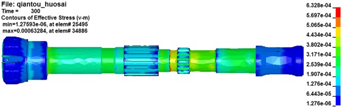
Fig. 9Stress distribution and stress wave transmission status at 400 μs
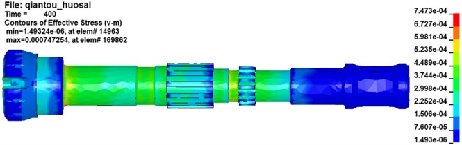
Fig. 9 is their stress distribution and stress wave transmission status at 400 μs. At this point, the maximum stress further has increased to 747.3 MPa, and the collision surface in the piston and the step face in the drill bit are the larger stress regions. With the further transmission of stress wave, the stress of the drill bit improves further and the stress waves have reached its end face. And the stress waves on the end face of the big end in the piston go on weaken and back to its small end.
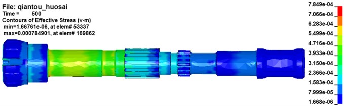
At 500 μs, on the drill bit the subsequent stress wave induced by the collision once again was superposed with the returning stress wave after reached the end. At this moment, the step face in the drill bit appears larger stress concentration status. And the step face in the drill bit becomes the larger stress region as shown in Fig. 10, and the maximum stress value is 784.9 MPa. The stress waves on the piston further weakened and its stress value decrease obviously.
Fig. 10Stress distribution and stress wave transmission status at 500 μs
3.3. Structure optimization
From the numerical simulation results of the collision between the piston and the drill bit, we can conclude that the stress waves transmitted from the collision surface to their end face in the early stage, but when reaching their own end face, they started to weaken gradually. Because the length of the piston is less than that of the drill bit and the transmitted velocity is the same in them, the stress waves on the piston is faster than the drill bit to complete a transmission cycle. Then we would find that the stress waves on the piston have almost disappeared at 500 μs, but at this moment the stress waves in the drill bit just begin weakening. Thus, the stress waves in the drill bit could come up a superposition with the stress waves induced by the next collision between the piston and the drill bit. This phenomenon above leaded to grow the stress concentration regions at the step face and thin neck area in the drill bit. And these stress concentration regions also are the dangerous and weak position of the drill bit. At the same time, the collision surface and the small end of the piston also are stress concentration regions from the simulation results above. So they are the dangerous and weak position of the piston. Moreover, the maximum effective stress of the piston is 665 MPa and that of the drill bit is 860.6 MPa from the analysis result of the NRAH dynamics simulation. Although both of them are less than the yield limit of their own material, their security coefficients are not high which of the piston only is 1.28 and the drill bit is 1.42. In summary, it is necessary to carry out structure optimization for the drill bit and the piston to improve reliability of the NRAH by weakening their stress concentration and adding to their security coefficient.
Fig. 11Schematic of the NRAH
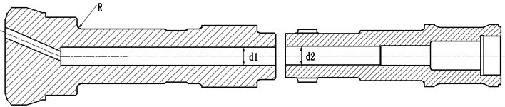
Combining the simulation analysis results above with the working mechanism of the NRAH, we presented an optimization strategy for the dangerous and weak position of the piston and the drill bit. The optimization strategy is to select these optimum values of the parameters, including the corner radius of the step face of the drill bit , the diameter of the central through hole of the drill bit and the diameter of the central through hole of the piston , as shown in Fig. 11 [18]. Through the analysis and comparison after several times, we got a set of optimum result that is 15 mm, is 50 mm, and is 55 mm on the premise that the overall performance of the NRAH cannot change poorer.
According to the structure optimization scheme above, the NRAH had completed the optimal design, especially to the piston and the drill bit. Then we had done the impact dynamics simulation for the NRAH after the optimization by reference to its previous boundary conditions and material properties in the Table 1. Through the arrangement of two simulation analysis results for the NRAH, we obtained the effective stress values of the piston before and after optimization in different time in Table 2 and the effective stress values of the drill bit before and after optimization in different time in Table 3.
Table 2Effective stress of the piston before and after optimization
Time (μs) | 50 | 100 | 150 | 200 | 250 | 300 | 350 | 400 | 450 | 500 |
Effective stress before optimization (MPa) | 564.6 | 555.8 | 665 | 600 | 584 | 632.8 | 647.9 | 643.8 | 542 | 298 |
Effective stress after optimization (MPa) | 417.4 | 509 | 586.5 | 583.2 | 579.5 | 586.3 | 590.9 | 551 | 440.6 | 267.1 |
Table 3Effective stress of the drill bit before and after optimization
Time (μs) | 50 | 100 | 150 | 200 | 250 | 300 | 350 | 400 | 450 | 500 |
Effective stress before optimization (MPa) | 482.8 | 429.2 | 520 | 505.2 | 488 | 535.1 | 830.6 | 747.3 | 860.6 | 784.9 |
Effective stress after optimization (MPa) | 538.7 | 561.1 | 538.6 | 570.7 | 582.8 | 621.8 | 673.1 | 719.7 | 805.5 | 787.1 |
It can be seen from the Table 2 that the maximum effective stress of the piston before optimization is 665 MPa, and after optimization it was reduced to 590.9 MPa. And we worked out the security coefficient of the piston by reference to material properties in the Table 1. It has been improved from 1.28 to 1.44.
As shown in the Table 3, the maximum effective stress of the drill bit before optimization is 860.6 MPa, and after optimization it is 805.5 MPa. So security coefficient of the drill bit has been also improved and it reaches 1.52.
4. Analysis of energy conversion and last impact velocity
4.1. Research of energy conversion regulation
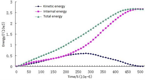
According to the calculation analysis of the collision process between them by using the LS-DYNA program, the energy conversion regulation of the piston and the drill bit was obtained from total energy reported in GLSTAT (see *database_glstat) and the energy values written on a part-by-part basis was in MATSUM (see *database_matsum) [19]. Then we extracted these data, including kinetic energy, internal energy and total energy of the piston on several different time points of the collision process. And the energy change curves of the piston were plotted, as shown in Fig. 12. It can be seen from the Fig. 12 that, when 0, the kinetic energy and the total energy is maximum value which is equal to 3130.5 J, and the internal energy is equal to 0 J. And the total energy of the piston is decreasing gradually with the energy transfer to the drill bit. Moreover, we can see that the kinetic energy of the piston is greater than its internal energy before 200 μs and they are equal at around 200 μs. After 200 μs, the internal energy becomes more than the kinetic energy, and it reaches the maximum value at 250 μs and then to begin to decrease.
The data, including kinetic energy, internal energy and total energy of the drill bit on several different time points of the collision process, can be extracted as well. So the energy change curves of the drill bit are plotted in Fig. 13. When 0 in the Fig. 13, the kinetic energy, the internal energy and the total energy of the drill bit are all zero. After the collision happened between the piston and the drill bit, the kinetic energy of the drill bit starts to increase gradually and reaches the maximum value at 250 μs, and then it begins to decrease to 0 J. In the process, the internal energy and the total energy are always increasing, and they get to their maximum value 2659.1 J when 500 μs.
Due to the collision between the piston and the drill bit, the kinetic energy of the piston transmits to the drill bit. But the drill bit is constrained to cause that the kinetic energy of the piston can’t be transmitted as the kinetic energy of the drill bit. So a part of energy is temporarily stored in the drill bit as the form of internal energy. According to the research of the conversion energy between the piston and the drill bit, we figured out that transfer ratio is 84.94 % in this process.
Fig. 12Energy change curves of the piston
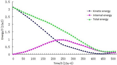
Fig. 13Energy change curves of the drill bit
Moreover, the axial velocity of the piston was obtained from the result document of the LS-DYNA program and change curve of the axial velocity was plotted, as shown in Fig. 14. It can be seen from the Fig. 14 that the axial velocity will decrease gradually with the increase of time, but to appear a rebounded after the piston impacts on the drill bit with velocity of 8.1 m/s. At the same time, we can find that the axial velocity is 0 when 420 us, and when 500 us, the axial velocity that is rebound status reaches the maximum value that is 1.36 m/s. From the analysis results above, the coefficient of restitution of the piston is 16.79 % within the range of 10-30 % of the last impact velocity by reference to the design requirements.
4.2. Research of last impact velocity of the piston
Performance parameters of the air hammer, including impact energy, impact frequency and structure parameter are closely related to the last impact velocity of the piston [19]. So the first thing is definition of the last impact velocity in the design process of the air hammer. In the traditional design, the last impact velocity determined depended on the mechanical property of the piston material and designers experience. And in general, the last impact velocity is not more than 10 m/s. The last impact velocity of the piston of the NRAH optimized is 8.1 m/s based on the calculation results above. In order to know how it affects the stress of the piston and the drill bit in the collision process, we performed a comparative analysis by taking a set of values of the last impact velocity around 8.1 m/s (6 m/s, 7 m/s, 9 m/s and 10 m/s). Then the maximum Von Mises stress of the piston and the drill bit were obtained for the different value of the last impact velocity above in calculation and analysis process. The relationships between the last impact velocity and the maximum Von Mises stress about the piston and the drill bit are shown in Fig. 15.
Fig. 14Change curve of axial velocity of the piston
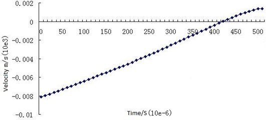
Fig. 15Change rule between the maximum Von Mises stress and the last impact velocity
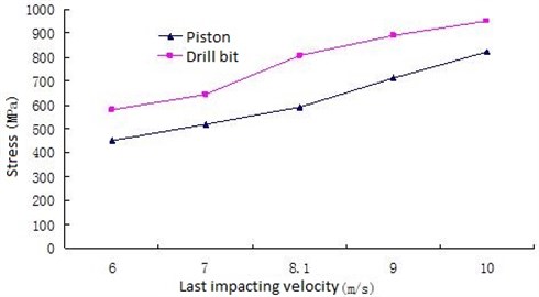
As shown in the Fig. 15, the maximum Von Mises stress of both the piston and the drill bit grows along with the increase of the last impact velocity in the collision process. But in any case, the stress of the piston is always less than that of the drill bit. So the drill bit should adopt a higher strength material than the piston. The relationship between the last impact velocity and the maximum Von Mises stress of the piston is an approximately linear increase, and the same to the drill bit. When the last impact velocity is 10 m/s, the maximum Von Mises stress of both the piston and the drill bit has been close to their own material yield strength, which is easy to result in their fatigue failure. This conclusion proves that in the pursuit of the high impact energy of the NRAH in the drilling process, we must not ignore the ultimate strength of the piston and the drill bit. Therefore, it is necessary to set an appropriate last impact velocity in order to ensure the long enough service life of the piston and the drill bit.
5. Experimental research
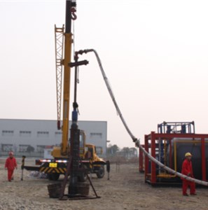
Base on the designing scheme of the NRAH optimized, we had completed its prototype processing. And then we planned to carry out an experiment of simulation field drilling for it [20-21]. This experiment aims at evaluating the feasibility of the structural optimization scheme of the NRAH by verifying whether it can perform the self-rotation and the rock-breaking ability. In order to effectively simulate the actual working condition of the field drilling, we designed an experiment bench, as shown in Fig. 16. In the course of the experiment, the back end of the NRAH was fixed and the front end of the drill bit faced the bottom of an iron cylinder, and a drilling pressure was generated by a Crane.
Fig. 16Experiment bench of the NRAH
In the process of drilling simulation experiment, we found these experimental phenomena about the NRAH as follow.
1) The collision between the piston and the drill bit of the NRAH produces high noise. The whole structure of the NRAH vibrates and quickly descends in a self-rotating motion. At the same moment a cloud of mist is ejected from the bottom of the drill bit.
2) When the quantity of flow of air compressor remained the same, we adjusted the exit pressure of the booster to increase gradually air pressure in the NRAH. Then we found that the NRAH didn’t start to work normally until the air pressure value is higher than the preset value. And after reaching the working pressure value, the higher air pressure will lead to sharper impact on the bottom of the iron cylinder.
Moreover, we performed a comparative analysis of the NRAH performance before and after the optimization through the computation simulation and experiment in Table 4. From the results in the Table 4, we can conclude that the performance of the NRAH after the optimization is superior to before the optimization. The safety coefficient of the piston is improved from 1.28 to 1.44 and the safety coefficient of the drill bit is improved from 1.42 to 1.52. At the same time, by analyzing the change rule of their energy and velocity in the collision process, we find that energy transfer rate after the optimization reaches 84.94 % as well as the rebound coefficient of the piston is reduced to 0.168.
Table 4The NRAH performance before and after the optimization
Impact energy (J) | Impact frequency (HZ) | Impact power (KW) | Rotation speed (rpm) | Last impacting velocity (m/s) | Energy transfer rate | Coefficient of restitution | Security coefficient of piston | Security coefficient of drill bit | |
Before optimization | 3135.9 | 23.4 | 73.35 | 42.9 | 8.3 | 80.25 % | 0.172 | 1.28 | 1.42 |
After optimization | 3247.8 | 23.8 | 77.31 | 43.6 | 8.1 | 84.94 % | 0.168 | 1.44 | 1.52 |
The experimental phenomenon of the simulation drilling shows that the NRAH not only perform a rotation but also adjust speed. And the frequency of the self-rotation of the NRAH can also be adjusted with the change of the air pressure provided by the air compressor. Through a comparative analysis, it is concluded that the performance of the NRAH is obviously improved. Hence, it fulfils the expectation of the optimized scheme of the NRAH to achieve the function of self-rotation and flexible rotation.
6. Conclusions
In this paper, we analyzed the problems of impact dynamics of the NRAH in operating condition with the LS-DYNA program according to the analysis of its working mechanism. The stress change rule of the piston and the drill bit before the optimization was obtained in the collision process. Then structure optimization of the NRAH was completed based upon the simulation results. Moreover, the relationships between the last impact velocity and the maximum Von Mises stress about the piston and the drill bit were studied, which was proved to be an approximately linear increase each other. Therefore, it should not be one-sided to require the high impact energy for the air hammer in the drilling process that will affect its service life. Finally, through the experimental research for the NRAH prototype, we found that the performance of the NRAH after the optimization is superior to before the optimization. So it is a reasonable structure optimization to achieve the expected designing effect.
References
-
Ai Jing-tao, Yu Rui, et al. The status quo and future development of gas drilling technology in the Sichuan gas field. Natural Gas Industry, Vol. 7, 2009, p. 39-41.
-
Lyons William C. Air and Gas Drilling Manual: Applications for Oil and Gas Recovery Wells and Geothermal Fluids Recovery Wells. Gulf Professional Publishing, 2009.
-
Luo Zheng, et al. Application of pneumatic hammer drilling technology in gas drilling. Drilling and Production Technology, Vol. 30, Issue 6, 2007, p. 9-10.
-
Whiteley Maxwell C., William P. England Air drilling operations improved by percussion-bit/hammer-tool tandem. SPE Drilling Engineering, Vol. 1, Issue 5, 1986, p. 377-382.
-
Su Yi-Nao, Chuan Zhou, Xiu-Rong Dou Operation characteristics analysis and process parameters selection of air drilling. Petroleum Exploration and Development, Vol. 2, 2005, p. 86-90.
-
Boginsky Vladimir P., et al. Annular air hammer apparatus for drilling wells. U.S. Patent No. 4,709,768, 1987.
-
Meng Qing-kun, Xiang-dong Wang, Xing-sheng Yu KQC series of air hammers for gas drilling in oil field. Oil Field Equipment, Vol. 11, 2007, p. 54-57.
-
Taylor W., et al. Effect of the air hammer on the hands of stonecutters. The limestone quarries of Bedford, Indiana, revisited. British Journal of Industrial Medicine, Vol. 41, Issue 3, 1984, p. 289-295.
-
Tiecheng Hou Shugang, et al. Characteristic analysis of safety drilling in air drilling. Petroleum Drilling Techniques, Vol. 6, 2007, p. 50-53.
-
Xiaobing Huang, Xiong Jianxin, Chen Cichang The experimental device for erosion of drilling tool of gas drilling. China Petroleum Machinery, Vol. 9, 2008, p. 1-3.
-
Lin Y. H., et al. Simulation of impact force and penetration rate of air hammer bit drilling. Chinese Journal of Rock Mechanics and Engineering, Vol. 24, Issue 18, 2005, p. 3337-3341.
-
Zukas Jonas Impact Dynamics. John Wiley & Sons, Inc., 605 Third Ave, New York, 1982, p. 452.
-
Elmarakbi A. M., Hu N., Fukunaga H. Finite element simulation of delamination growth in composite materials using LS-DYNA. Composites Science and Technology, Vol. 69, Issue 14, 2009, p. 2383-2391.
-
Heimbs Sebastian Virtual testing of sandwich core structures using dynamic finite element simulations. Computational Materials Science, Vol. 45, Issue 2, 2009, p. 205-216.
-
Tai Yuh-Shiou, Chia-Chih Tang Numerical simulation: The dynamic behavior of reinforced concrete plates under normal impact. Theoretical and Applied Fracture Mechanics, Vol. 45, Issue 2, 2006, p. 117-127.
-
Tang Y., et al. Study on stress distribution of a subsea Ram BOP body based on simulation and experiment. Engineering Failure Analysis, Vol. 50, 2015, p. 39-50.
-
Karagiozova D., Mines R. A. W. Impact of aircraft rubber tire fragments on aluminum alloy plates: II – Numerical simulation using LS-DYNA. International Journal of Impact Engineering, Vol. 34, Issue 4, 2007, p. 647-667.
-
Guo Y. S., Zhang Y., Cheng M. K. Hammer rod optimization of large tonnage air hammer. Applied Mechanics and Materials, Vol. 644, 2014, p. 81-84.
-
Liu Zhao, et al. Study on generation mechanism and stability analysis for air hammer of air-bearing slider. IEEE International Conference on Mechatronics and Automation, 2014.
-
Tang Y., et al. Parameter estimation of a delay time model of wearing parts based on objective data. Mathematical Problems in Engineering, 2014, p. 9.
-
Han G., Bruno M. S., Dusseault M. B. 3D simulation of rock breakage with air hammers in gas-well drilling. SPE Gas Technology Symposium, Society of Petroleum Engineers, 2006.
About this article
The work was supported by the Natural Science Foundation of China (Grant No. 51274171), National Science and Technology Major Project (Grant No. 2011CS05026-001) and the Graduate Student Innovation Fund of School of Mechatronic Engineering, Southwest Petroleum University (CX2014BZ04).
