Abstract
This paper deals with modeling and evaluation of suspension system with a pneumatic actuator controlled by Proportional Integral Derivative (PID) controller. A non-linear mathematical model of the dynamic suspension system with two degrees of freedom is developed. The controller is designed by setting proper gain values obtained by comparing three tuning methods - Ziegler Nicolas, Refined Ziegler Nicolas and Optimal control. The time response of the air suspension system is contrasted with the passive suspension system due to the road disturbance modeled as a single bump input. The proposed model limits suspension travel, minimizes passenger acceleration and keeps body displacement within bound.
1. Introduction
The suspension provides vibration isolation of the passengers from road irregularities. It also influences the traction and road holding abilities of the wheel. The vehicle passive suspension system is coil or leaf springs in combination with hydraulic or pneumatic shock absorbers. A softer spring provides good comfort and stiff spring offers better handling characteristics whereas good suspension design requires compromise between passenger ride comforts and handling. These conflicting demands have been subject of many previous studies and led to development of active suspension [1-5]. Two degree-of-freedom quarter car model is preferred to study vibrations in the vertical direction [6]. The control algorithms such as PID, Linear Quadratic (LQ) and Fuzzy logic are based on feedback control strategies [7]. The PID offers advantages of automatic tuning, gain scheduling, continuous adaptation and design simplicity. The three modes of the PID controller, proportional gain, Integral time constant and Derivative time constant, are used to get desired performance and robustness characteristics of the control system [8-10].
In this study, design and control of pneumatic actuator for nonlinear vehicle suspension system is considered. The model is approximated as a first order system. Controller design is based on Ziegler Nicolas tuning method and Optimal control. The response of the PID controller is compared for air suspension system and passive suspension system.
2. Air suspension modeling
The air suspension provides improved stability and superior comfort under different loads and road conditions. Suspension design is initiated by developing an appropriate mathematical model of the system. Certain assumptions are to be made for modeling: both vehicle body and axle assembly are rigid bodies, the tyre is a linear spring with equivalent stiffness, damping force of the tyre is neglected, passive suspension system is considered as a spring and vibration damper in parallel connection, the stiffness of the spring and damping of the vibration damper is considered and friction in the damper is neglected. The dynamically controlled pneumatic actuator is attached in parallel with the passive suspension system.
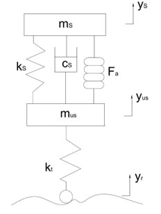
Modeling of pneumatic actuator. The pneumatic actuator model is represented in Fig. 1. Pneumatic actuator is a rubber chamber with elastic barrier which contains air under pressure.
Fig. 1Quarter car air suspension model
The vertical force exerted by actuator is the gauge pressure multiplied with the effective area and it can be expressed as:
The force developed by the pneumatic actuator () can be evaluated by differentiating the above equation with respect to vertical displacement:
Consider adiabatic process for air, dynamic pressure can be given as:
As a result pressure increases with displacement. Due to compression, positive pressure arises, which results in decrease of volume. In the dynamic stiffness equation (4), the reservoir pressure , gauge pressure and atmospheric pressure are taken into account:
Air suspension dynamics. The pneumatic actuator suspension model is presented in Fig. 1. The model consists of sprung mass which represents a portion of the total body mass and unsprung mass representing one of the wheel and axle. The assumption is that the mass carried by each wheel corresponds to the static weight supported by suspension system. The road input is assumed to be irregular road surface and actuator force ‘’ acts on the vehicle body mass upwards. and are the vertical displacement of the vehicle body and axle respectively. If represents the tyre radial stiffness, suspension spring stiffness. The represents the damping force available in the damper.
By using Newton’s law, the dynamic equation of motion for a suspension system is derived by the following differential equation:
When the following states are introduced, the input and output vectors are:
The suspension model is represented as:
The suspension travel is the relative displacement between the sprung mass and the unsprung mass. Tyre displacement is the difference between the unsprung mass displacement and the road surface at any instant.
3. PID control system
The performance of PID controller for air suspension is enhanced by proper selection of the parameters proportional gain (KP), integral gain (Ki), derivative gain (Kd) values. This paper attempts to design PID controller using Ziegler Nicolas, refined Ziegler Nicolas, and optimal control tuning methods. A PID control system shown in Fig. 2.
Fig. 2PID controlled suspension system
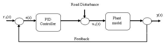
Error signal is estimated from the differences in reference input signal to the system output . The control signal from the controller to the plant model is equal to the proportional gain () times the magnitude of the error plus the integral gain () times the integral of the error plus the derivative gain () times the derivative of the error. The PID controller is mathematically represented as:
Best control performance is achieved when choosing appropriate values of proportional gain, integral time, derivative gain. The selection of the PID parameters is called as tuning and the best tuned method is identified by comparing the performances of three different tuned systems, Ziegler-Nichols, refined Ziegler-Nichols and optimal tuning methods. The Error signal is denoted by the following equation:
The suspension plant model is approximated to a first order plus dead time (FOPDT) model using [9] standard transfer function approach. From the FOPDT model transfer function the transportation lag , time constant and the static gain are obtained. The above parameters are used to determine the controller parameters. Evaluating the equation at 0, yields the model parameters obtained as: 7.0134, L = 2.9867, 0.547 and .
The Ziegler-Nichols PID tuning is a commonly used feedback loop in control systems. This approach is utilized for comparison purpose only.
Refined Ziegler-Nichols tuning. The refined Ziegler-Nichols settings are introduced by adding a new parameter ‘’ in the proportional action of the controller [11]. The new parameter ‘’ can reduce the overshoot to acceptable levels, and thus gives good set point response. When ‘’ value is less than unity the control equation becomes:
The PID gain values are defined and on further simplification the equation is refined as:
Optimal control method tuning. The general form of the optimal PID controller design should have good rejection performance on the given disturbance:
Tuning methods are proposed [12] for the disturbance signal and the error signal is . The gain values , , of the PID controller are evaluated from the following relations:
4. Simulation
The vehicle parameters [13] (Table 1) of quarter car model are used in this analysis. The simulation experiment was carried for with the single bump disturbance input.
Table 1Vehicle parameters
Vehicle body mass in kilograms | 285.3 | Tyre stiffness in N/m | 190000 |
Axle and tyre mass in kilograms | 59.5 | Suspension damping in Ns/m | 1000 |
Suspension spring stiffness in N/m | 16812 |
5. Single bump road input
A road surface is an unsystematic with sudden speed bumps. Here air suspension system response is analyzed by a single speed bump (Fig. 3). To limit the effort of the random input, simpler road model is used [14]. It consists of a crest of height 5 cm each. A road input, yr of height 0.05 m, is described by setting ‘’ as 0.025 in the below equation and it is used to study the system response.
Fig. 3Road bump
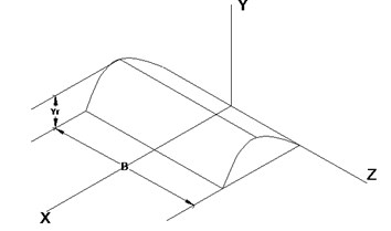
The road bump is mathematically described [15] as:
6. Results and discussions
From the results, it is found that addition of pneumatic actuator plays an extensive work in the reduction of vehicle body displacement, suspension travel and body acceleration when compared to that of passive suspension system. The road bump is shown in Fig. 4.
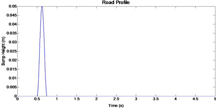
Fig. 4. Single bump road input
Fig. 5Vehicle body displacement for 50 mm single bump road input
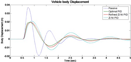
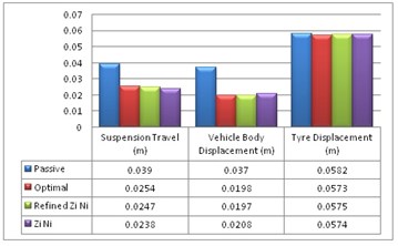
For given road input the peak vehicle body displacement (Fig. 5) in optimal (0.0197 m) is lower than passive (0.0370 m) suspension system. The Suspension travel (Fig. 6) of optimal PID system is better than passive when considering the peak overshoot, system response and settling time. The vehicle tyre displacement (Fig. 7) for optimal PID system shows marginal improvement when compared to passive system.
Based on the observation from vehicle body acceleration (Fig. 8), the Ziegler-Nichols method offers minimum overshoot but the settling time is too long when compared to other control methods. From the values it is observed that when both the body acceleration and the settling time are considered, the optimum result is obtained by optimal PID system.
From the Fig. 9, the body acceleration is reduced by 41.4 % and an improvement in settling time of 11.4 % for optimal control method when compared with a passive system. The vehicle body displacement, suspension travel and tyre displacement (Fig. 10) are compared, and it is found that the settling time and the response for the optimum PID controller gives favorable results.
Fig. 6Vehicle suspension travel for 50 mm single bump road input
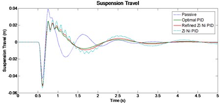
Fig. 7Vehicle tyre displacement for 50 mm single bump road input
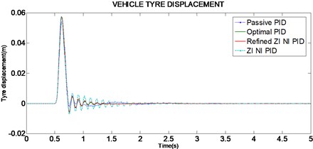
Fig. 8Vehicle body acceleration for 50 mm single bump road input
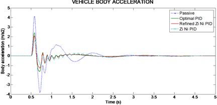
Fig. 9Maximum body acceleration for different PID controls
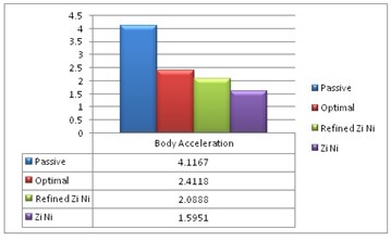
Fig. 10Maximum overshoot for various parameters of the system
7. Conclusions
The objective of the study is to optimize the performance of suspension system with a pneumatic actuator controlled by PID controller. Considering the dynamics of the actuator, the different control methods are evaluated by a single speed bump rather than complicated road model as the scope of study is to analyze the controller response to vibration. It is concluded that:
• The body acceleration is reduced and an improvement in settling time for optimal control method.
• The vehicle body displacement, suspension travel and tyre displacement are compared and it is found that the settling time and the response for the optimum PID controller gives better results than passive system.
• Based on the overall performance, it is concluded that the optimal PID is the most suitable control method for the air suspension system.
References
-
J. Y. Wong Theory of Ground Vehicles. John Wiley & Sons, 2001.
-
Uisoy A. G., D. Hrovat Stability robustness of LQG active suspensions. Proceedings of the American Control Conference, San Diego, California, 1990, p. 1347-1356.
-
Alleyne A., Hedrick J. K. Nonlinear adaptive control of active suspensions. IEEE Trans. on Control Systems Technology, Vol. 3, No. 1, 1995.
-
Hrovat D. Applications of optimal control to advanced automotive suspension design. Journal of Dynamic Systems, Measurement and Control, Vol. 115, No. 2 (B), 1993, p. 328-342.
-
Rakheja S., Afework Y., Sankar S. An analytical and experimental investigation of the driver seat suspension system. Vehicle System Dynamics, Vol. 23, 1994, p. 501-524.
-
K. Prabu, J. Jancirani Development of a new suspension system for passengers to improve occupants comfort. Journal of Mechanical Engineering, Vol. 1, No. 4, 2011, p. 7-13.
-
V. Gavriloski, D. Danev, K. Angushev Mechatronic approach in vehicle suspension system design. 12th IFToMM World Congress, Besançon (France), 2007.
-
Danlel E. Rlvera, Manfred Morarl, Slgurd Skogestad Internal model control. 4. PID controller design. Ind. Eng. Chem. Process Des. Dev., Vol. 25, 1986, p. 252-265.
-
Li Mei, Li Zhongxing, Shen Xufeng, Guo Jiwei Study on PID control for semi-active air suspension for riding comfort. 2nd WRI Global Congress on Intelligent Systems, 2010, p. 47-50.
-
C. C. Hang, K. J. Wstrom, W. K. Ho Refinement of the Ziegler-Nichols tuning formula. IEEE Proceedings D, Vol. 138, No. 2, 1991, p. 111-118.
-
Dingyu Xue, Yang Quan Chen, Derek P. Atherton Linear feedback control: analysis and design. The Society for Industrial and Applied Mathematics, 2007, p. 187-209.
-
O. A. Dahunsi, J. O. Pedro, O. T. Nyandoro System identification and neural network based PID control of servo-hydraulic vehicle suspension system. South African Institute of Electrical Engineers, Vol. 101(3), 2010, p. 93-105.
-
R. Rajamani, J. K. Hedrick Performance of active automotive suspensions with hydraulic actuators: theory and experiment. Proceedings of American Control Conference, Maryland, 1994.
-
K. Prabu, J. Jancirani Investigation on the performance of the quarter car model suspension system using electromagnetic actuator. IJMAE, Vol. 20(1), 2012, p. 1-8.
-
Jung-Shan Lin, Ioannis Kanellakopoulos Nonlinear design of active suspensions. IEEE Control Systems Magazine, Vol. 17(3), 1997, p. 49-59.
About this article
Research work has been supported by Anna University Chennai and the authors are grateful to the University.
