Abstract
Aiming to reduce the impact of substation noise on the lives of surrounding residents, improving the low and middle frequencies acoustic performance of traditional resistive mufflers in indoor substations is significant. The paper is based on the resonance sound absorption mechanism, and for the first time applies multi-frequency resonance noise reduction technology to the research field of indoor substation noise control, proposing a multi-frequency resonant muffling structure. The acoustic performance of the proposed muffler unit is investigated through theoretical and numerical analysis. The measured noise data of the indoor substation is used as sound excitation in the numerical analysis. The results show that at frequencies of 100 Hz, 200 Hz, 300 Hz, 400 Hz, and 500 Hz, the noise in indoor substations is significantly reduced by the multi-frequency resonant muffling structure. The paper provides references for the application of multi-frequency resonant mufflers in the field of noise control of indoor substations.
Highlights
- For the first time, multi-frequency resonant muffler technology has been applied to the research field of indoor substation noise control.
- A multi-frequency resonant muffler structure is proposed to effectively control noise at specific frequencies within the mid to low-frequency range, in response to the obvious low-frequency line spectrum noise characteristics exhibited by indoor substations.
- Optimization design work was carried out to address the issue of noise reduction frequency deviation in the system under theoretical design parameters, and precise control of noise at specified frequencies was achieved.
1. Introduction
To reduce the impact of substation radiation noise on the lives of surrounding residents, an increasing number of substations in urban areas adopt indoor layout. Due to the leakage of indoor noise along the ventilation pipe, the ventilation duct becomes a weak link in the noise isolation between the indoor and outdoor main transformer. Installing sound insulation barriers outdoors, replacing sound insulation doors, and installing mufflers at the air inlet and exhaust outlets are important methods of indoor noise control. An on-site photo of Xi’an 110 kV Changming indoor substation’s noise reduction measures with muffler louvers is shown in Fig. 1. Classic mufflers are mainly resistive mufflers, which have satisfying silencing effects on high-frequency noise. However, substation noise is mainly dominated by power frequency multiplier line spectrum noise. Considering the 50 Hz AC power supply used in China, the substation noise exhibits obvious line spectrum characteristics at frequencies such as 100 Hz, 200 Hz, and 300 Hz (as shown in Fig. 2). Traditional resistive mufflers have limited silencing capabilities and longer muffling pipes need to be designed to realize the low-frequency noise muffling performance. The Helmholtz resonant cavity structure has strong selectivity and designability for sound absorption frequencies and has broad application prospects in precise control of low-frequency noise [1-2]. The combination of the Helmholtz resonant cavity and the traditional resistive muffler structure can achieve impedance composite low-frequency line spectrum and high-frequency broadband silencing [3-4], which is consistent with the noise reduction needs of indoor substations and can effectively control indoor substation noise radiation, further can improve the acoustic environment of people living around the substation.
Existing muffler units are resistant or resistive muffler structures. Composed of porous materials, the resistance muffler units are primarily designed for reducing low-frequency noise. Researchers have conducted a lot of research on the noise reduction effect of the muffler [5-8]. Shao et al. [9] proposed a muffler with a membrane structure and multiple Helmholtz cavities. The muffler frequency can be adjusted by changing the number of membranes. Amine et al. [10] explored a combination of origami structure and Helmholtz resonator. The acoustic impedance of Helmholtz resonator can be adjusted by changing the volume of the origami structure, which realizes the adjustment of acoustic characteristics. Although the design and improvement of muffler structures have been greatly developed, the processing difficulty of the structure, limitations of application conditions, muffler frequency, and bandwidth have restricted the practical application of the muffler design. It’s vital to seek a noise reduction structure that is easy to process, has low resistance loss, has high, low, and middle frequencies noise reduction performance, and meets the noise reduction and ventilation needs in substations.
Fig. 1On-site view of the noise reduction measures of the silencer louvers at Xi’an 110 kV Changming indoor substation
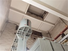
a)
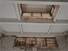
b)
In order to solve the problem of weak low-frequency muffler performance of traditional resistive mufflers in indoor substations, the paper introduces a multi-frequency resonant muffler structure considering the low-frequency muti-line spectrum characteristics of indoor substation noise.
Fig. 2Noise curve diagram of Xi’an 110kV Changming indoor substation
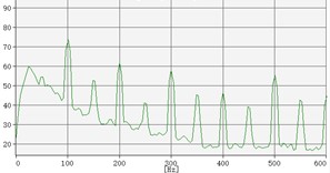
Fig. 3Helmholtz resonance muffler
2. Basic principles of resonant sound absorption
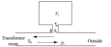
Resonance is a phenomenon in which the amplitude of an oscillating system increases sharply under the action of a periodic external force. When the frequency of the external force is the same as or very close to the natural oscillation frequency of the system, Helmholtz resonant cavity utilizes the principle. The air in the cavity is excited to vibrate when a sound wave is incident at the entrance of the resonant cavity. The resonance amplitude and the energy consumed are the largest when the frequency of the incident sound wave is consistent with the natural frequency of the resonant cavity structure. The basic structure of a Helmholtz resonant muffler is shown in Fig. 3. The opening of the resonant cavity is connected to a muffler pipe with a cross-sectional area of . The length of the connecting pipe is , the cross-sectional area is , and the cavity volume is .
is the acoustic impedance of Helmholtz resonance muffler. The corresponding acoustic resistance and acoustic reactance can be expressed as follows: , and , where is the fluid density, is the fluid sound speed, is the side length of the connecting pipe section, and is the effective length of the connecting pipe.
The acoustic performance of a Helmholtz resonance muffler can be expressed by the difference in sound pressure level between the inlet end face and the outlet end face. The calculation formula of the muffler’s sound attenuation amount is:
When the sound attenuation amount of the muffler is zero, the resonant frequency of the Helmholtz resonance muffler is obtained as follows:
When the natural frequency of the Helmholtz muffler is consistent with the frequency of the incident sound wave, the acoustic resistance is minimum. At the same time, the vibration speed reaches the maximum, and the sound absorption capacity is optimal. Resonance frequency is an important parameter in the design of Helmholtz muffler, which includes connecting pipe section length , connecting pipe section width , connecting pipe length , cavity section length , cavity section width , and cavity height . Therefore, the target frequency can first be determined according to the actual application environment, and then any five of the six variables can be determined. Finally, the value of another unknown variable can be obtained by solving Eq. (2) to complete the parameter design of the Helmholtz muffler.
3. Multi-frequency resonance silencer design
Mufflers with different resonant frequencies can be installed on the silencer pipes to achieve efficient and precise noise control for the obvious power frequency doubling line spectrum characteristics of noise radiation in indoor substations. The multi-frequency resonance muffler design mainly determines the target frequency based on the actual application environment, determines the natural frequencies of each Helmholtz resonance structure of the combined muffler, and completes the calculation of each structural parameter. Carrying out multi-frequency resonance silencing design can achieve efficient and precise control of low-frequency multi-line spectrum noise in indoor substations.
3.1. Acoustic modeling
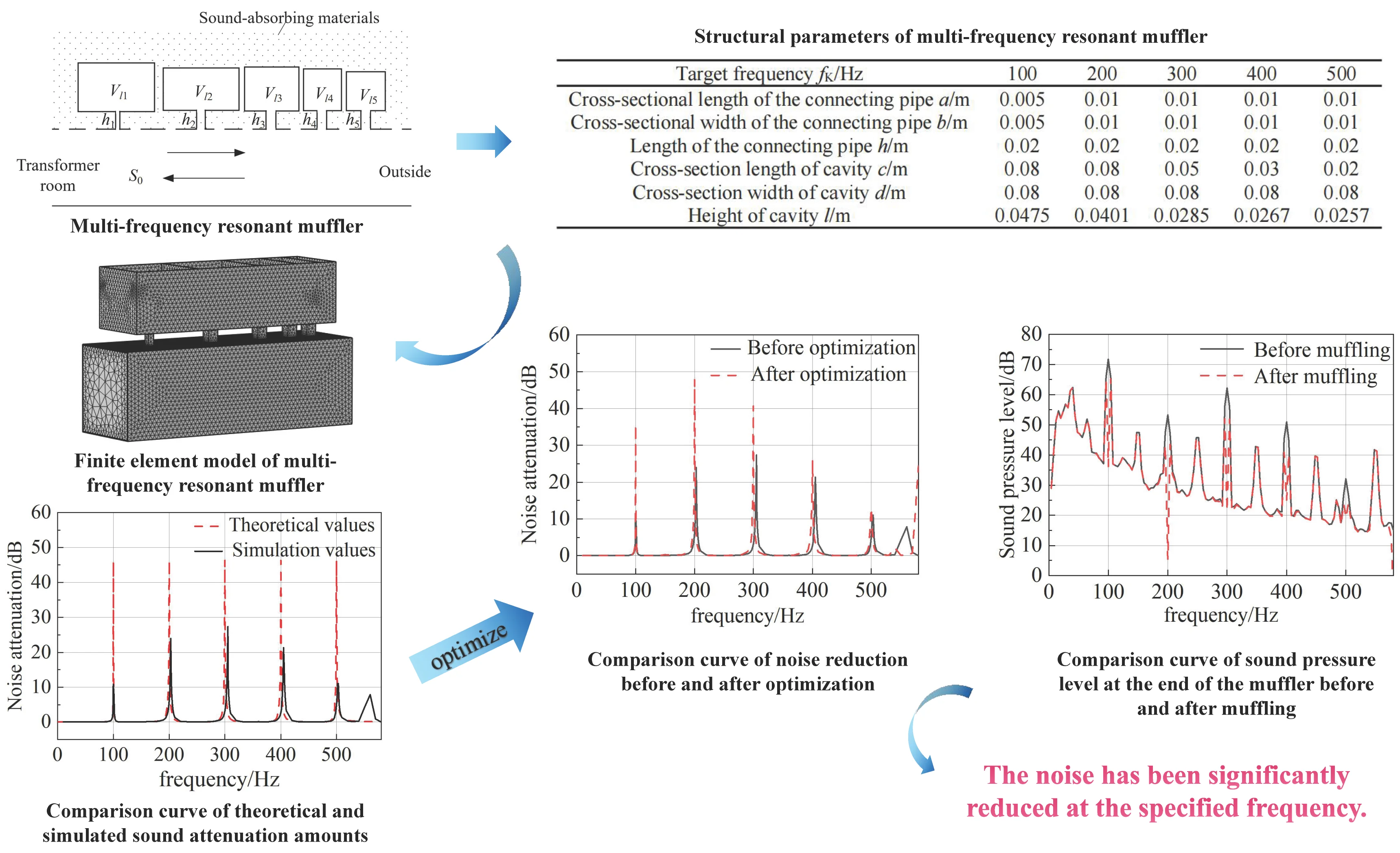
Five mufflers with different resonance frequencies are installed on the main silencing pipe to achieve targeted silencing of 100 Hz, 200 Hz, 300 Hz, 400 Hz, and 500 Hz noise. Perforated plates are installed on the pipe wall. The outside is filled with sound-absorbing materials. The simplified model of the multi-frequency resonant impedance composite muffler is shown in Fig. 4.
The resonant frequencies of each resonant sound-absorbing structure are 100 Hz, 200 Hz, 300 Hz, 400 Hz, and 500 Hz from left to right. The paper will not do dissipative muffler research in detail since the relative study is mature. The study proposed focuses on the reactive muffler part to solve the poor low-frequency performance of indoor variable muffling. According to the natural frequencies of each resonant sound-absorbing structure, the design parameters of the multi-frequency resonant muffler are obtained in Table 1.
According to the structure parallel relationship, the calculation formula for the total acoustic impedance of the multi-frequency resonant muffler is obtained as follows:
where is the impedance of the Helmholtz resonant cavity numbered . By substituting the design parameters in Table 1 into Eq. (3), the total impedance modulus of the multi frequency resonant muffler can be obtained, and then the noise reduction curve through Eq. (1) can also be obtained.
Fig. 4Multi-frequency resonant muffler
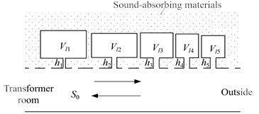
Table 1Structural parameters of multi-frequency resonant muffler
Target frequency / Hz | 100 | 200 | 300 | 400 | 500 |
Cross-sectional length of the connecting pipe / m | 0.005 | 0.01 | 0.01 | 0.01 | 0.01 |
Cross-sectional width of the connecting pipe / m | 0.005 | 0.01 | 0.01 | 0.01 | 0.01 |
Length of the connecting pipe / m | 0.02 | 0.02 | 0.02 | 0.02 | 0.02 |
Cross-section length of cavity / m | 0.08 | 0.08 | 0.05 | 0.03 | 0.02 |
Cross-section width of cavity / m | 0.08 | 0.08 | 0.08 | 0.08 | 0.08 |
Height of cavity / m | 0.0475 | 0.0401 | 0.0285 | 0.0267 | 0.0257 |
3.2. Multi-resonance silencing performance
The finite element model of the multi-frequency resonant muffler is established according to the design parameters in Table 1, as shown in Fig. 5. Solve the multi-frequency resonant muffler finite element model and obtain the structural sound attenuation performance curve as shown in Fig. 6.
Fig. 5Finite element model of multi-frequency resonant muffler
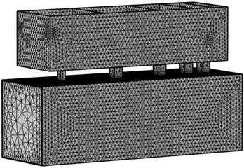
Fig. 6Comparison curve of theoretical and simulated sound attenuation amounts
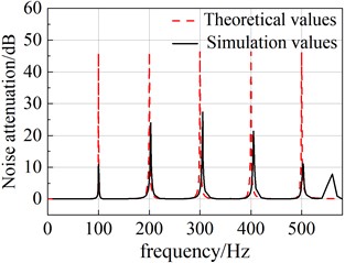
Similar to the theoretical calculation results, the simulation calculation sound attenuation curve has obvious peaks near 100 Hz, 200 Hz, 300 Hz, 400 Hz, and 500 Hz. The resonance frequencies of the simulation and theoretical calculation results are consistent, and the correctness of the theoretical and simulation calculations can be verified. The curve also has an obvious peak at the frequency of 560 Hz for the reason that the cavity and the elastic plate have structural resonance at the frequency. Due to internal friction and air friction, part of the vibration energy is converted into heat energy and consumed. At the same time, it can be seen from Fig. 6 that under the same design parameters, there is a certain deviation in the peak frequency between simulation and theory. The reason for the phenomenon is that the calculation results are not accurate enough due to the correction and simplification of the formula in the theoretical calculation, while simulation technology has developed so far and is more mature. When the model mesh is fine enough and the quality is high enough, the calculation results will be more accurate and closer to reality. In indoor variable multi-frequency resonance sound attenuation design, theoretical calculations can be used to obtain preliminary design parameters and finite element simulation can be further used to achieve refined system design.
4. Indoor variable multi-resonance sound attenuation optimization design
The sound attenuation amount of each target frequency is used as the optimization objective function. The height of each cavity is the optimization parameter. The natural frequency of Helmholtz resonator and the height of cavity calculated theoretically are set as the initial parameters. The parameter variation range is ±100 %. The Nelder-Mead optimization algorithm is used to carry out multi-frequency resonance noise elimination optimization design. The corresponding cavity heights from 100 Hz to 500 Hz are obtained as 0.0479 m, 0.0412 m, 0.0295 m, 0.0275 m, and 0.0259 m, respectively. The comparison curve of the noise reduction volume before and after the multi-resonance noise reduction optimization is shown in Fig. 7.
Fig. 7Comparison curve of noise reduction before and after optimization
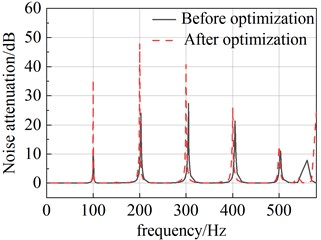
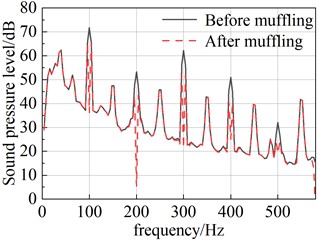
Fig. 8Comparison curve of sound pressure level at the end of the muffler before and after muffling
After the optimization, the muffler frequency is consistent with the target frequency, and the muffler amount at each target frequency is significantly improved compared, which realizes a sufficient use of the muffler’s muffler performance.
To verify the effectiveness of the resonant sound absorption indoor variable noise reduction method proposed in the article, we measured the noise of a certain indoor substation and calibrated the measuring tool (Sound Level Meter) before the measure, with an error of 0.03 dB, which meets the basic measurement requirements. Using the measured noise data as an incentive to understand the multi-frequency resonance silencing performance by comparing the noise data before and after multi-frequency resonance silencing. The model before frequency resonance silencing is an acoustic model that only includes the main silencing duct. The measured noise of the indoor substation is loaded at the beginning of the main silencing duct, and the end noise radiation data is extracted. The model after multi-frequency resonance silencing is attached to 5 main silencing ducts. The acoustic model excitation and result data extraction of different frequency resonant cavities are similar to the model before multi-frequency resonant silencing. The comparison curve of the sound pressure level at the end of the muffler before and after multi-frequency muffling under indoor variable actual noise spectrum load is shown in Fig. 8.
It can be seen from Fig. 8 that the end of the main silencing pipe before multi-frequency resonance silencing shows obvious line spectrum noise characteristics, which are larger at 50 Hz multiplier frequencies such as 100 Hz and 200 Hz. The sound pressure level curve decreases significantly at 100 Hz, 200 Hz, 300 Hz, 400 Hz, and 500 Hz after multi-frequency resonance silencing. Taking all analyzed frequency bands together, the noise sound pressure level drops from 74.13 dB to 68.88 dB by muffling. The comprehensive noise reduction amount reaches 5.25 dB. The noise reduction effect is resultful.
5. Conclusions
Given the ventilation and noise reduction requirements of indoor substations, the paper carried out multi-frequency resonance silencing theoretical modeling, structural design, simulation verification, optimization design, and actual measurement effect verification. Through analysis, it is verified that the multi-frequency resonance silencing technology can effectively control the noise radiation of indoor substations and have feasibility and significant advantages in ventilation and noise reduction of indoor substations. Taking the multi-frequency resonant muffler as the analysis object, we carried out the noise elimination design work based on resonant sound absorption and obtained the following conclusions:
1) When the resonant frequency of the multi-frequency resonant muffler is equal to the frequency of the incident sound wave, the acoustic impedance is minimum, the resonant cavity vibrates significantly, the sound wave energy of the muffler pipe is consumed in large quantities, and the sound attenuation performance is fully exerted.
2) Compared with the multi-resonance silencing performance simulation and theoretical calculation results, the resonance frequencies of the two are consistent, which verifies the correctness of the theory and simulation calculations.
3) Using the measured noise data of an indoor substation as an incentive, its silencing performance is verified by comparing the noise data before and after multi-frequency resonance silencing, which provides theoretical and application reference for the application of multi-frequency resonance mufflers in the field of noise control in indoor substations.
References
-
D. Wu, N. Zhang, C. M. Mak, and C. Cai, “Hybrid noise control using multiple Helmholtz resonator arrays,” Applied Acoustics, Vol. 143, pp. 31–37, Jan. 2019, https://doi.org/10.1016/j.apacoust.2018.08.023
-
S.-H. Seo and Y.-H. Kim, “Silencer design by using array resonators for low-frequency band noise reduction,” The Journal of the Acoustical Society of America, Vol. 118, No. 4, pp. 2332–2338, Oct. 2005, https://doi.org/10.1121/1.2036222
-
H. Long, Y. Cheng, and X. Liu, “Asymmetric absorber with multiband and broadband for low-frequency sound,” Applied Physics Letters, Vol. 111, No. 14, p. 14350, Oct. 2017, https://doi.org/10.1063/1.4998516
-
Z. Zhang, D. Yu, J. Liu, B. Hu, and J. Wen, “Transmission and bandgap characteristics of a duct mounted with multiple hybrid Helmholtz resonators,” Applied Acoustics, Vol. 183, p. 108266, Dec. 2021, https://doi.org/10.1016/j.apacoust.2021.108266
-
D. P. Jena, J. Dandsena, and V. G. Jayakumari, “Demonstration of effective acoustic properties of different configurations of Helmholtz resonators,” Applied Acoustics, Vol. 155, pp. 371–382, Dec. 2019, https://doi.org/10.1016/j.apacoust.2019.06.004
-
Z. Lu, Y. Cui, M. Debiasi, and Z. Zhao, “A tunable dielectric elastomer acoustic absorber,” Acta Acustica united with Acustica, Vol. 101, No. 4, pp. 863–866, Jul. 2015, https://doi.org/10.3813/aaa.918881
-
Zhang. X., “Development of dry-type transformer acoustic enclosure muffler,” Kunming University of Science and Technology, No. 9, p. 90, 2008.
-
Y. Zhao et al., “Design and research of the “loop” – shaped metastructure composite muffler,” Journal of Harbin Engineering University, Vol. 43, No. 9, pp. 1376–1382, 2022.
-
H. Shao, H. He, Y. Chen, X. Tan, and G. Chen, “A tunable metamaterial muffler with a membrane structure based on Helmholtz cavities,” Applied Acoustics, Vol. 157, p. 107022, Jan. 2020, https://doi.org/10.1016/j.apacoust.2019.107022
-
A. Benouhiba. et al., “Origami-based auxetic tunable Helmholtz resonator for noise control,” Smart Materials and Structures, Vol. 30, No. 3, 2021, https://doi.org/10.1088/1361-665x/abe180
About this article

This work was financially supported by Science and Technology Project of State Grid Shaanxi Electric Power Company Limited (5226KY22000W).
The datasets generated during and/or analyzed during the current study are available from the corresponding author on reasonable request.
The authors declare that they have no conflict of interest.
