Abstract
A general methodology for modeling and analysis of a single leg walking mechanism of quadruped robot is presented in this paper to solve the problems of more drive elements, more complex structure and control system in existing single-leg walking mechanism. The principle scheme and scale optimization design of proposed walking mechanism are completed according to the requirements of the foot end trajectory curve and Grashof’s criterion. The models of kinematics and dynamics of presented mechanism have been built. By numerical calculation, the variations of displacement, the angular velocity and moment of the equivalent crank are discussed. The results indicate that the kinematic and dynamic properties of the optimized mechanism are better than those before optimization. Furthermore, these results provide a basis for the structural design of a single leg walking mechanism of quadruped robot.
1. Introduction
In recent years, leg walking robots have become a hot topic of research for domestic and foreign scholars. It is well known; the degree of freedom is the first concern in the design of walking robot [1]. The more degrees of freedom a walking robot has, the better its walking flexibility and obstacle avoidance ability. The shortcomings of this kind of robot are many driving components, complex control, poor motion performance, high energy consumption and impact. Therefore, the research of leg mechanism with less freedom has been widely concerned by scholars [2]. Buehler [3] designed a robot with fewer freedom called SCOUT, which can achieve motion behaviors such as walking, turning, climbing stairs, and running. Poulakakis [4] developed Scout II with four legs with two DOF (degree of freedom), its walking trajectory is not ideal. Kenichi [5] designed one DOF leg mechanism based on the crank slider mechanism, its foot trajectories are ellipses. Hao [6] designed a quadruped robot, its leg mechanism has one DOF, and consists of crank rocker mechanism and a pantograph mechanism. Basic features of this system are reduced number of DOFs, compactness, and straight walking with only one actuator. However, the study is not perfect and further research is needed. This paper is organized as follows. Section 2 introduces the mechanical design and optimal modelling of the leg mechanism. In Section 3, a brief discussion of the kinematic and dynamic for single leg mechanism is presented. In Section 4, numerical results for presented single leg mechanism are obtained and discussed. Finally, the conclusions are presented in Section 5.
2. Optimal theory of single leg mechanism
According to the author [6], an exact mechanism scheme with one DOF of a quadruped robot’s single leg motion can be shown as Fig. 1(a). In Fig. 1(a), the leg generates an approximately straight-line trajectory for the foot with respect to the body, which is shown by the dotted line in Fig. 1(b). In Fig. 1(b), the foot’s trajectory curve is not very smooth, and not a precise straight-line when the foot is positioned ground contact, thus its dynamic behavior is poor. It is necessary to optimize the scale of the design mechanism to ensure the solid line motion law in Fig. 1(b).
Fig. 1Mechanism for single leg movement
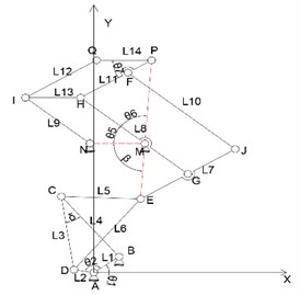
a) The mechanism scheme
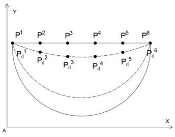
b) The trajectory of point P
2.1. Design variable
In Fig. 1(a), the parallelogram mechanism EJHFP is used to amplify and mirror image of the trajectory of point E. The trajectory of point P can be fully determined by the crank rocker mechanism ABCDE. Therefore, the length of each component and the initial position angle of the frame and crank in the mechanism ABCDE are selected as the design variables, namely .
2.2. Objective function
In order to ensure the straight line trajectory of point P, the Euclidean distance sum between the target point and the corresponding mechanism movement point in Fig. 1(b) must be the smallest during the movement of the single-leg mechanism, so the expression of the objective function can be expressed as:
According to the author [6], the displacement equation of point P is written as:
where, the expressions and meanings of all parameters can be found in the authors’ research [6].
2.3. Restrictions
2.3.1. Transmission angle constraints
The transmission angle of the mechanism ABCDE in Fig. 1(a) can be obtained from the angle between bar DC and bar CB (as 90°, ; other 180°-) [7]. In order to ensure the force transmission performance, cannot be less than the allowable value 40°. Therefore, the constraint condition of the transmission angle can be written as:
2.3.2. Grashof’s criterion
Because the mechanism ABCDE is crank-rocker mechanism, the length of each component must meet the Grashof’s criterion, the corresponding constraint conditions are:
The CDE is a triangle, thus its side length geometric constraints can be expressed as:
3. Kinematic analysis and dynamic analysis of single leg mechanism
3.1. Kinematic analysis
The velocity and acceleration equations of point P can be obtain by deriving Eq. (2), namely:
where, and are the velocity components of point E in coordinate system . and are the acceleration components of point E in coordinate system . Their expressions can be found in the authors’ research [6].
3.2. Dynamic analysis
In order to determine the dynamic behavior of the optimized mechanism, it is necessary to analyze the equivalent mechanism of the mechanism. Here, the crank is selected as the equivalent component, its angular velocity, , can be used to illustrate the stability of the overall mechanism. Therefore, can be expressed as:
where, and are the equivalent moment of inertia and angular velocity of the crank in its initial position, respectively. and are the work and equivalent moment of inertia when the crank angle is , respectively. Their relation can be expressed as:
The equivalent moment of inertia can be obtained from Eq. (19):
where , and are the moment of inertia, mass and angular velocity of member , respectively. and are the velocity components of the center of mass of member in coordinate system , and can be obtained by differentiating the corresponding centroid displacement components and of member .
According to the principle of constant energy before and after equivalent, the equivalent moment, , of the crank can be derived as:
4. Example
According to author [6], both geometric parameters and performance parameters of presented mechanism are as follows: 52.5 mm, 26.8 mm, 203.9 mm, 205.8 mm, 196.9 mm, 219 mm, 200 mm, 250 mm, 150 mm, 100 mm, 52.05°, 65.89 g, 33.69 g, 256.11 g, 258.52 g, 247.32 g, 275.03 g, 251.2 g, 314 g, 188.4 g, 125.6 g. All components are made of aluminum alloy. The single-leg mechanism carries 300 N.
From Section 2, the optimization model of presented mechanism is a nonlinear optimization problem with fourteen constraints on a goal function. In order to avoid derivation and falling into a local optimal solution, a genetic algorithm is used as an optimum searching technique. The objective is to guide point P along a planar trajectory, defined by a set of 5 target points , whose coordinates are , , , , and . The value ranges of design variables are:, , , .The optimal solutions of design variables are as follows: 56.8 mm, 36.3 mm, 151.6 mm, 162 mm, 144.1 mm, 189 mm, 74.48°. The total length of presented mechanism was reduced by 18.26 %.
Fig. 2Curve of step length and height before and after optimization
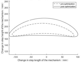
The results of kinematic simulation based on Section 3.1 are shown in Fig. 2. In Fig. 2, the step height and step length after optimization are larger than before optimization. It is shown the obstacle surmounting ability and travel efficiency of designed mechanism have been greatly improved.
The driving torque and angular velocity of the crank are respectively 200 N.mm and 1 rad/s. The masses of all bars after optimization are 71.3 g, 45.55 g, 190.46 g, 203.4 g, 181.01 g, 237.24 g, 251.2 g, 314 g, 188.4 g, 125.6 g. The result of the dynamic analysis of the mechanism based on Section 3.2 is shown in Fig. 3. In Fig. 3, the amplitude of after optimization is significantly smaller than before optimization, shows the stability of the mechanism has been significantly improved after optimization.
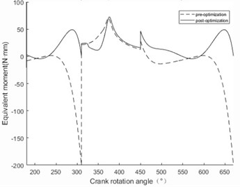
According to section 3.2, the equivalent moments of the designed mechanism are visually represented in Fig. 4. As can be seen from Fig. 4, the variation amplitude of the equivalent torque after optimization is significantly reduced compared with that before optimization. The smaller the variation range of equivalent torque, the better the working performance of the mechanism. It is worth noting that there is a sudden change in equivalent torque when the sole is in contact with the ground. The equivalent torque mutation after optimization is reduced by 80 % compared with that before optimization. Therefore, the flexible impact during the robot movement can be alleviated to a great extent.
Fig. 3The angular velocity of the designed mechanism
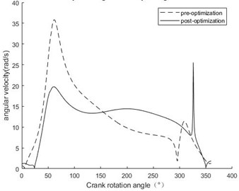
Fig. 4The equivalent moments of the designed mechanism
5. Conclusions
A general methodology for the optimal synthesis, kinematic and dynamic modelling and simulation of the leg mechanism with one DOF was presented and discussed throughout this work. The research conclusions are as follows: (1) According to author [6], an optimal approach to the dimensional synthesis of presented mechanism has been proposed. By means of evolutionary theory, a global optimization solution has been implemented, in order to generate a precise straight-line trajectory for the foot with respect to the body, according to both dimensional and kinematic fitness criteria. (2) The displacement, velocity and acceleration equations of presented mechanism are derived, and completed the corresponding kinematics analysis. The results show that, under the condition of keeping the step length basically unchanged, the step height of the optimized mechanism is increased by 30 % compared with that before optimization, and the obstacle-surmounting ability of the leg mechanism is effectively improved. (3) Established an equivalent model of the leg mechanism of a single-degree-of-freedom quadruped robot, derived the change rule of the angular velocity of the equivalent crank. The results show that the amplitude of the angular velocity of the equivalent crank after optimization is significantly smaller than before optimization, thus, the stability of the mechanism after optimization has been significantly improved. (4) Taking the crank as the equivalent component, the equivalent torque of the designed single-leg mechanism of the robot is derived, and the variation curve of the equivalent torque before and after optimization is obtained by simulation. The simulation results show that the optimized mechanism's equivalent torque amplitude is significantly reduced, especially the moment abrupt change when the sole is in contact with the ground is reduced by 80%, which greatly reduces the flexible impact during the robot movement and makes the movement process more stable.
The results not only verify the rationality and reliability of the present research, but also show that presented methodology can provide useful guidance for the further design of the outline of each component.
References
-
M. Kaneko, M. Abe, and S. Tachi, “Basic considerations on degrees of freedom of multi-legged locomotion machines,” Journal of the Robotics Society of Japan, Vol. 2, No. 2, pp. 142–150, 1984.
-
M. Buehler, A. Cocosco, K. Yamazaki, and R. Battaglia, “Stable open loop walking in quadruped robots with stick legs,” in IEEE International Conference on Robotics and Automation, pp. 2348–2353, 1999.
-
M. Buehler, R. Battaglia, A. Cocosco, G. Hawker, J. Sarkis, and K. Yamazaki, “SCOUT: A simple quadruped that walks, climbs, and runs,” in International Conference on Robotics and Automation, pp. 1707–1712, 1998.
-
I. Poulakakis, E. Papadopoulos, and M. Buehler, “On the stable passive dynamics of quadrupedal running,” in International Conference on Robotics and Automation, pp. 1368–1373, 2003.
-
K. Iida, Y. Hayami, T. Hira, T. Yasuno, and T. Kamano, “Evolutionary acquisition for moving performance of reduced DOF’s quadruped robot,” in SICE-ICASE International Joint Conference, pp. 3005–3010, 2006.
-
R. Hao, C. Guo, Z. Han, and Y. Han, “Design and research of single leg walking mechanism of quadruped robot,” Vibroengineering Procedia, Vol. 49, pp. 130–135, May 2023, https://doi.org/10.21595/vp.2023.23267
-
H. Sun, Z. Chen, and W. Ge, Ji Xie Yuan Li. Beijing: Higher Education Press, 2013.
-
C. Zhang, Ji Xie Dong Li Xue. Beijing: Higher Education Press, 2000.
About this article

The authors have not disclosed any funding.
The datasets generated during and/or analyzed during the current study are available from the corresponding author on reasonable request.
The authors declare that they have no conflict of interest.
