Abstract
In view of the problem that the electro-erosion fault signal is rare and weak during motor operation, and the database is seriously imbalanced, this paper proposes an ASMOTE-CFR training model based on adaptive minority oversampling technology. Four bearing vibration acceleration signals in different states were collected through experiments, and each signal obtained 32 sets of energy features using wavelet packet decomposition. Then ASMOTE technology is used to balance the energy features of electro-erosion fault signal. And construct a vector matrix combined by energy features and bearing fault state features. Finally, the collaborative filter model of matrix decomposition is used to train and identify. The results show that the recognition rate of the ASMOTE-CFR model proposed in this paper is 98.46 %, which improves by 7 % compared with the traditional CFR, which verifies the effectiveness of this method.
1. Introduction
The formation mechanism of bearing electrical erosion fault is complex, during the operation of the motor, the coupling capacitance between the stator, rotor, winding and other components of the motor will form a circuit provided by the common-mode voltage inside the motor, which will cause the motor to generate shaft voltage and shaft current. The electro-erosion fault of the bearing is that the shaft current is generated by the shaft voltage during the operation of the bearing. The shaft current breaks through the oil film, and sparks are generated through the lubricating oil film in the inner and outer rings and the working surface of the rolling elements, causing local melting and unevenness on the surface, that is early electro-erosion fault [1]. As a special type of fault that affects the life of the bearing, the failure to suppress it in time will seriously shorten the service life of the bearing. In the field of practical engineering, how to accurately predict the electro-erosion fault state is an urgent problem to study. In the process of obtaining comprehensive monitoring data, the explosion of data makes traditional identification methods less and less accurate. With the development of machine learning, collaborative filtering and recommendation technology has shown unique advantages in solving the problem of “information overload”. The process of monitoring the condition of motor bearings will appear the problem of collecting signal overload. collaborative filtering and recommendation technology is an effective solution to solve the problem of information overload. This paper [2] applies the theory of collaborative filtering to the field of fault diagnosis of civil aircraft. And calculates the similarity between interrupt layers by Pearson’s method and vector cosine method.
This paper [3] uses a collaborative filtering algorithm based on real-time status data to recommend faults for online electric multiple units, and further provides fault accessibility schemes through the knowledge base. However, the above methods are memory-based collaborative filtering that relies on the calculation of fault similarity, and the sparsity of the fault data often leads to inaccurate similarity calculations, which cannot identify more general conditions and more general failures. In the practice of bearing condition monitoring, a large amount of bearing normal condition data is often obtained, compared to which the bearing failure state data is much less [4]. For supervised learning, this creates a data imbalance problem, and in simple terms, one class has significantly more samples than another class [5]. From a learning point of view, minority classes usually contain more important classification information, and a small number of samples are more expensive to misclassify [6]. The collaborative filtering algorithm for rolling bearing fault identification proposed in the paper [7] only considers the balanced training set, and may generate an unsatisfactory classification model in the face of unbalanced data, and some information about bearing fault status is often drowned in a large number of bearing normal data.
Aiming at the data imbalance problem in practical applications, collaborative filtering based on matrix decomposition has excellent performance in dealing with the sparse problem of faulty data [8]. Adaptive minority oversampling technology can solve the problem of sparse fault data [9]. In this paper, aiming at the problems that the electro-erosion fault data monitored under complex working conditions is small and it is not easy to quickly diagnose the bearing fault type in a large amount of data, an ASMOTE-CFR system suitable for motor bearing electro-erosion fault identification is proposed. Firstly, the typical characteristics are extracted from the vibration data of each state of the bearing. and then the number of samples of the electro-erosion fault data to be synthesized is determined by calculating the imbalance of the electro-erosion fault data in the data set. Then, the equalization of the typical characteristics of bearings by ASMOTE technology is realized. Then, the equalized typical feature matrix is used as the bearing fault characteristic scoring matrix of the collaborative filtration system, and then a scoring matrix that can accurately describe each state of the bearing is designed, and finally the matrix of these two different characteristics are organically combined to obtain the joint scoring matrix of bearing state recognition. And the collaborative filtering algorithm based on matrix decomposition identifies the electro-erosion fault. Compared with traditional CFR, the new method can mine more fault information and achieve a higher recognition rate.
2. Adaptive SMOTE oversampling technology
The adaptive synthetic minority sample oversample method is to set the new number of minority sample samples to be generated according to the balance degree of the sample data distribution [10]. Then, its distribution ratio is calculated for each minority sample, and then a different number of new samples are synthesized for minority samples [11], that is, Adaptive Synthetic Minority Oversampling, and abbreviated as ASMOTE. Based on the bearing data subsequent in this article, the process of ASMOTE algorithm is introduced in detail [14].
Step 1: Calculate the imbalance.
Assuming the smallest number of electro-erosion fault failures in the selected group bearing data, assuming group , the number of bearings in normal condition is the largest, assuming group , the imbalance of the bearing sample data as shown in Eq. (1):
Step 2: Calculate the number of minority samples to be synthesized.
The unbalance in step 1 is further calculated according to Eq. (2) for the minority sample size to be synthesized:
where when 1, the number of new samples synthesized is exactly balanced with the number of samples of the majority class.
Step 3: Find the minority sample in the sample data, and use the Euclidean distance method to find the close neighbors of the minority sample dataset [15]. In these neighbors, suppose is the number of samples of the majority class among neighbors. Note that the proportion of the number of samples of most classes in the adjacent samples of is , as shown in Eq. (3):
Step 4: For each minority class sample obtained in step three, normalize it as shown in Eq. (4):
Step 5: For a small number of samples in the bearing experimental data, the number of new samples should be synthesized according to the following Eq. (5):
Step 6: Among the neighbors of each minority type of electro-erosion fault sample to be synthesized, select 1 electrical erosion fault sample according to Eq. (6):
where (0 << 1) is the proportion factor of a small number of new samples to be synthesized, repeat the above steps for adaptive oversampling until the number required in step 5 is met.
2.1. Collaborative filtering recommendation techniques
The core idea of collaborative filtering is [11]: By analyzing the user’s existing behavior, find a neighbor user similar to the target user in a large number of user groups, and predict the target user’s preferences according to the neighbor user's evaluation of a certain information [13].
Next, taking the movie system as an example, the collaborative filtering algorithm based on matrix decomposition is introduced in detail:
Table 1 shows the User-Movie rating table. from which the user-Movie rating matrix is available, as is shown in Eq. (7):
where represents the user, indicates the different types of movies, is listed in row , and the column element is recorded as what the user scores on the movie . The movie recommendation system aims to [16].
For the movies without the ratings of the user , give the prediction score of the user through the recommendation system, and the corresponding recommendation is given to the user accordingly.
The idea of the collaborative filtering algorithm based on matrix decomposition is to decompose the scoring matrix with higher dimension into the product of two lower dimensional matrices that are the user latent factor matrix and the movie latent factor matrix, respectively.
Where is the number of latent factor features, the inner products of and constantly approach the original matrix by iterating, and then make the score prediction for the items that users do not score. As shown in Eq. (8):
Table 1“User-Movie” score table
Movie 1 | Movie 2 | Movie | ||
User 1 | ||||
User 2 | ||||
User m |
The collaborative filtering algorithm based on matrix decomposition is used to learn the best user potential factor matrix and the movie potential factor matrix to predict the score of the user items [17]:
For the existing n score records, the loss function for each score was calculated using error squares. As shown in Eq. (10):
To prevent overfitting, a regularization term was added to the q. As shown in Eq. (11):
where is the regularization coefficient, further, the gradient descent method is used to handle the above minimization problem. The core problem of the matrix factorization model is to minimize , which minim the overall loss function of the above formula by finding suitable parameters and .
2.2. Construction of the adaptive oversampling score matrix
In order to diagnose bearing electro-corrosion faults accurately from a large number of unbalanced data, this paper selects db3 wavelet base for each set of vibration data collected, performs 5-layer wavelet packet decomposition, and constructs 32 wavelet packet energy features into a bearing typical characteristic matrix. As shown in Table 2.
Table 2Bearing feature score table
The means that the vibration signals of various fault states and normal states of the group bearings are collected. represents the collected group bearing vibration data, extracting typical characteristic values.
In the actual collected sample data, the vibration data of bearing electro corrosion failure is very small, therefore, for this unbalanced data set, in this paper, ASMOTE technology is adopted to adaptively oversample a few classes of bearing electro corrosion fault data. In order to achieve a balanced sample set. Assuming that the electro-erosion fault data is increased from the previous group to group after ASMOTE, the typical characteristic score table of the bearing samples in group after ASMOTE is as Table 3. Where represents the data of various states of group bearings after ASMOTE, including fault status and normal state. indicates the extraction of ab typical features from group bearing sample data.
Table 3ASMOTE rear bearing typical feature score table
2.3. Build a joint scoring matrix based on adaptive oversampling
The difficulty to be solved by introducing collaborative filtration technology into the identification of bearing electro-erosion faults is how to construct a suitable scoring matrix to complete the prediction according to the characteristics of bearing electro-erosion data. In view of this problem, we have established a scoring matrix that can reflect the typical characteristics of the bearing in Table 3. The score level reflects the fault characteristics at each moment of the bearing, that is, the degree of “preference” in the recommendation system. Further, a state scoring matrix reflecting each bearing state is designed for different bearing states. In the bearing state scoring matrix, the maximum value 1 is given to the known bearing status score, while the minimum value is given to the absent state score, as shown in the Table 4.
Table 4Bearing feature score table
State | 1 | ||||||
State | 1 | ||||||
State | 1 |
As shown in the Table 4, the bearing has states. For the one section of bearing vibration data collected, if the corresponding bearing state is , the maximum value is 1 at this position, and the other states is given the minimum value .
This method is used to assign bearing status score to the sample after ASMOTE, which constitutes the bearing condition scoring matrix, and finally, the typical feature matrix reflecting the bearing characteristics and the bearing condition scoring matrix reflecting the bearing state are organically combined to obtain the joint scoring matrix of bearing condition recognition.
2.4. ASMOTE-CFR bearing fault identification method
The specific operation methods of how to use ASMOTE-CFR to identify the various states of bearings are described in detail.
Assuming that the vibration signal data , of the group of rolling bearing exists, the sample data has a total of group after ASMOTE, and there are different types of states for this group of signal data. Now that the state of the first group training data is known, our goal is to use ASMOTE-CFR to identify the state of the subsequent group test data .
Further, the group I signal data is extracted from 32 typical bearing eigenvalues using wavelet packet decomposition for normalization, and the normalized eigenvector is obtained as follows:
where .
According to the characteristic vector , design the bearing characteristic scoring table as shown in the previous section, and further get the corresponding scoring matrix , as shown in Eq. (13):
According to the various states of the bearing, and then design the bearing state characteristic scoring table as shown in Table 4, to get the corresponding scoring matrix , as shown in Eq. (14):
In the training data , for known states, the score is given a maximum value of 1, while for unknown states, the score is given a minimum value of .
For the test data , the status is unknown, and the score is given a zero value. Combine the bearing feature scoring matrix and the bearing state scoring matrix to obtain the joint scoring matrix for the bearing state recognition:
where , and .
For motor bearing failures, our ASMOTE-CFR approach to identify the following objectives:
The joint scoring matrix is decomposed into and , that is , and the prediction score of the test data to the state is given according to the two feature matrices, specifically as follows:
By finding the optimal parameters and , the overall loss function is minimized, as specified in Eq. (17):
where is the regularization coefficient.
Finally, the parameters and are optimized by gradient descent and alternating least squares methods, thus obtaining the prediction score of the state from the test data :
Then the state corresponding to the highest score is the state of the identified test data .
3. Experimental verification and analysis
In this paper, the proposed ASMOTE-CFR method is used to verify the experimental data of bearing electro-erosion failure for the vibration data of complex motor bearings.
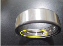
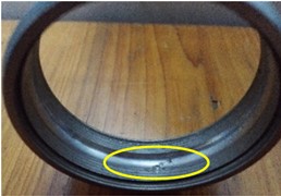
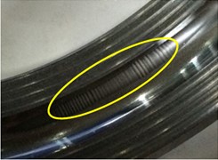
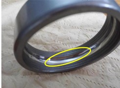
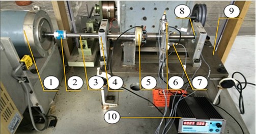
The electro-erosion fault failure test bench is shown in Fig. 2, and the data acquisition system is the PULSE system of Danish B&K. The experimental data of outer ring pitting corrosion, outer ring crack, outer ring electrical corrosion failure and normal. Four states of deep groove ball bearing type 6205EKA were collected shown in Fig. 1. (Photos were taken by Huanke Cheng in the fault diagnosis laboratory of Hunan University of Science and Technology). In the data acquisition, the motor speed is 600 rpm and 1200 rpm respectively, the sampling frequency is 16384 HZ, and the sampling time is 10 s. A total of 402 groups of outer ring pitting corrosion, 390 groups of outer ring cracks, 85 groups of bearing electro-erosion failures, 423 groups of normal groups, and a total of 1300 groups of data samples were selected.
First, 32 energy bearing features were collected for each data group by using wavelet packet decomposition Then 1300 sets of sample data are divided into training and test sets according to the 8:2 ratio. Among them, there were 1040 groups of training sets, which were 322 groups of outer ring pitting, 312 groups of outer ring cracks, 68 groups of outer ring electro-erosion and 338 groups of normal data. and then ASMOTE technology was used to balance the electro-erosion fault in the training set.
In the ASMOTE process, we set the following parameters: the unbalance is calculated to be 0.5, and this paper sets 3 times oversampling, that is, the electro-erosion fault data has been increased from the original 68 groups to the current 204 groups after ASMOTE.
Fig. 1Four states of deep groove ball bearing type 6205EKA: a) Outer ring pitting; b) outer ring crack; c) outer ring electro-erosion fault; d) outer ring normal
a)
b)
c)
d)
Fig. 2The electro-erosion fault failure test bench: (1) electric motor; (2) insulated coupling; (3) principal axis; (4) supporting bearing pedestal; (5) current loading device; (6) test bearing’s bearing pedestal; (7) vibration acceleration sensor; (8) insulated bearing; (9) base; (10) current simulator
The electro-erosion fault data after ASMOTE is as follows Table 5.
Table 5Electro-erosion fault data in the post-ASMOTE training set
0.1221 | 0.1324 | 0.1231 | 0.1230 | 0.1133 | 0.1259 | |||
0.0281 | 0.0253 | 0.0278 | 0.0213 | 0.0281 | 0.0239 | |||
0.0056 | 0.01632 | 0.0034 | 0.0152 | 0.0121 | 0.01172 | |||
0.011 | 0.0138 | 0.0122 | 0.0138 | 0.01383 | 0.01379 |
Next, ASMOTE-CFR is used for state recognition of 1176 sets of data in the training set and of 260 sets of data in the test set.
Table 6 shows joint score of bearing condition recognition for the test set and the training set. where - is the test set and - is the training set.
Table 6Joint scoring of bearing state recognition of test set and training set after ASMOTE
0.03723 | 0.04367 | 0.04491 | 0.11187 | 0.08138 | 0.11093 | |||
0.06781 | 0.06941 | 0.07192 | 0.07784 | 0.12364 | 0.07972 | |||
0.04327 | 0.04329 | 0.04204 | 0.06093 | 0.07948 | 0.06539 | |||
0.00843 | 0.00834 | 0.00757 | 0.01893 | 0.00741 | 0.01328 | |||
0.02081 | 0.01921 | 0.02024 | 0.01273 | 0.01238 | 0.01478 |
Table 7Scoring results under the best model parameters
State 1 | 0.51327 | 0.32603 | 0.48235 | –0.0311 | 0.9972 | 0.0534 | ||
State 2 | 0.20326 | 0.18564 | 0.24582 | 0.0632 | 0.0963 | –0.0767 | ||
State 3 | 0.14359 | 0.26347 | 0.19732 | 0.99914 | 0.0693 | 0.0232 | ||
State 4 | 0.16326 | 0.10587 | 0.11904 | 0.054597 | –0.0934 | 0.9994 |
Table 7 shows the scoring results under the best model parameters, where - is the test set and - is the training set.
Table 8ASMOTE-CFR test set recognition rate
8 | 9 | 10 | 11 | 12 | |
0.002 | 81.72 % | 83.21 % | 76.39 % | 97,34 % | 90.56 % |
0.0025 | 83.12 % | 79.34 % | 80.34 % | 96.89 % | 89.05 % |
0.003 | 83.20 % | 79.19 % | 79.38 % | 97.45 % | 83.24 % |
0.0035 | 77.19 % | 80.36 % | 79.03 % | 98.03 % | 91.06 % |
0.004 | 76.82 % | 82.52 % | 78.95 % | 98.46 % | 81.58 % |
From Table 8 it can be seen that when the regularization coefficients = 0.004 and 11, the bearing condition score of the test set reaches 98.46 %. When = 11, takes0.02, 0.0025, 0.003 and 0.0035, the bearing status of the test set reaches 97.34 %, 96.89 %, 97.45 % and 98.03 % accuracy respectively. The performance of the model on the test set is evaluated, and it is proved that the model has good generalization ability under this parameter.
Table 9CFR test set recognition rate
8 | 9 | 10 | 11 | 12 | |
0.002 | 88.46 % | 87.31 % | 88.08 % | 89.23 % | 91.92 % |
0.0025 | 85.00 % | 85.00 % | 82.69 % | 88.46 % | 91.92 % |
0.003 | 84.61 % | 84.62 % | 82.70 % | 90.38 % | 91.15 % |
0.0035 | 84.23 % | 84.23 % | 81.15 % | 90.76 % | 91.19 % |
0.004 | 83.08 % | 84.23 % | 88.85 % | 90.76 % | 91.15 % |
Table 9 show the results of the model directly identified by CFR technology using different regularization coefficients and feature number , relying on the training set and cross-validation set. As can be seen from Table 9 when the regularization coefficient = 0.002 and = 12, the scoring result of the test set reaches 91.92 %. When = 12, take 0.0025, 0.003 and 0.0035, the bearing state of the test set reaches 91.92 %, 91.15 % and 91.19 % accuracy respectively. In comparison, the highest recognition accuracy of CFR can only reach 91.92 %.
Fig. 3. compares the fault identification accuracy of ASMOTE-CFR and CFR methods for different regularization coefficients when 11. In contrast, ASMOTE-CFR has an accuracy rate of more than 98 % when 0.004,11. Table 10 shows the specific identification of the various states of the bearing when 0.004, 11 is in ASMOTE-CFR.
The results show that ASMOTE-CFR can effectively identify various states of bearings, especially for the electro-erosion failure of motor bearings, the accuracy rate more than 98 %, and the optimized parameters have good generalization ability.
Fig. 3ASMOTE- CFR and CFR technology accurate recognition rate comparison
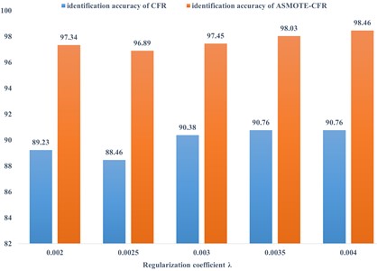
Table 10Test set identification effect
State | Number of tests | Identify the results right error | Recognition rate |
Outer ring crack | 80 | 78 2 | 97.5 % |
Outer ring Pitting | 78 | 77 1 | 98.7 % |
Outer ring electro-erosion fault | 17 | 17 0 | 100 % |
Outer ring normal state | 85 | 84 1 | 98.82 % |
Total | 260 | 256 4 | 98.755 % |
4. Conclusions
In this paper, aiming at the problem that the electro-erosion fault signal is rare and weak during motor operation, and the database is seriously imbalanced, a set of ASMOTE-CFR method suitable for motor bearing electro-erosion fault identification is proposed, and the results show that:
1) The overall identification rate of bearing faults by ASMOTE-CFR method exceeds 97.5 %, and the identification rate of electro-erosion faults reaches 100 %.
2) Compared with the data test without ASMOTE, the recognition accuracy of ASMOTE-CFR method can be improved by 7 % under the same parameters.
References
-
E. H. E. Bouchikhi, V. Choqueuse, and M. E. H. Benbouzid, “Current frequency spectral subtraction and its contribution to induction machines’ bearings condition monitoring,” IEEE Transactions on Energy Conversion, Vol. 28, No. 1, pp. 135–144, Mar. 2013, https://doi.org/10.1109/tec.2012.2227746
-
J. H. Zhu, J. H. Liu, and X. J. Yang, “Study on failure causes and prevention of aviation rolling bearings,” Equipment Management and Maintenance, Vol. 2020, No. 13, pp. 67–68, 2020, https://doi.org/10.16621/j.cnki.issn1001-0599.2020.07.34
-
M. L. Guo, “Research and Realization of EMU’s Operation and maintenance decision-making recommended technology based on knowledge base,” M.E. thesis, Beijing Jiao tong University, Beijing, China, 2015.
-
J. W. Zhang, L. M. Guo, and X. M. Yang, “Improved algorithm for oversampling and random forest for unbalanced data,” Computer Engineering and Applications, Vol. 56, No. 11, pp. 39–45, 2020, https://doi.org/10.3778/j.issn.1002-8331.1908-0338
-
Y. T. Yan, Y. W. Zhu, Z. B. Wu, and Y. W. Zheng, “SMOTE oversampling method for constructive overlay algorithm,” Computer Science and Exploration, Vol. 14, No. 6, p. 975, Jun. 2020, https://doi.org/10.3778/j.issn.1673-9418.1905091
-
Z. L. Zhang and Y. B. Feng. Z. K. Zhao, “An Oversampling method for unbalanced datasets based on SVM,” Computer Engineering and Applications, Vol. 56, No. 23, pp. 220–228, 2020, https://doi.org/10.3778/j.issn.1002-8331.2006-0449
-
K. Dai, “An empirical study on data sampling problem of imbalance classification,” Central China Normal University, 2020.
-
G. Wang, Y. He, Y. Peng, and H. Li, “Bearing fault identification method based on collaborative filtering recommendation technology,” Shock and Vibration, Vol. 2019, pp. 1–9, May 2019, https://doi.org/10.1155/2019/7378526
-
S. H. Yang, C. H. Zhou, Y. M. Jiang, F. Q. Zhang, and T. Zhang, “An improved oversampling algorithm for unbalanced data BN-SMOTE,” Computer and Digital Engineering, Vol. 48, No. 9, pp. 2108–2113, 2020, https://doi.org/10.3969/j.issn.1672-9722.2020.09.007
-
X. H. Zhao, “Research on ensemble classification algorithm of unbalanced data based on oversampling,” Chongqing University, 2020.
-
F. F. Zhang, L. M. Wang, and Y. M. Chai, “An improved oversampling unbalanced data ensemble classification algorithm,” Journal of Chinese Computer Systems, Vol. 39, No. 10, pp. 2162–2168, 2018.
-
Y. H. He, “Identification method of motor bearing current damage based on collaborative filtration,” Hunan University of Science and Technology, 2020.
-
S. Wang, X. M. Sun, and Y. B. Gao, “Personalized product recommendation method based on neural collaborative filtering,” information technology, Vol. 355, No. 6, pp. 143–147, 2021, https://doi.org/10.13274/j.cnki.hdzj.2021.06.026
-
J. Xu, “Research on adaptive unbalanced data classification,” Beijing Jiao tong University, 2020.
-
Z. Sun, Q. Song, X. Zhu, H. Sun, B. Xu, and Y. Zhou, “A novel ensemble method for classifying imbalanced data,” Pattern Recognition, Vol. 48, No. 5, pp. 1623–1637, May 2015, https://doi.org/10.1016/j.patcog.2014.11.014
-
P. Y. Li, “Personalized recommendation algorithm based on collaborative filtering,” Hebei University of Architecture and Engineering, 2022.
-
L. Z. Cheng, “Research on Hybrid Collaborative Filtering Algorithm for Mature Users Based on Matrix Decomposition,” Anhui University of Finance and Economics, 2022.
About this article

Acknowledgements Financial support from National Natural Science Foundation of China (51575178), financial support from Hunan Natural Science Foundation of China (2018JJ2120).
The datasets generated during and/or analyzed during the current study are available from the corresponding author on reasonable request.
The authors declare that they have no conflict of interest.
