Abstract
A machine learning method (MLM) developed based on fuzzy logic control (FLC) has been proposed to control the vibration of the car’s suspension systems. To apply the MLM, a quarter car model with two degrees of freedom has been established via MATLAB/Simulink. The reduction of the vertical car body’s acceleration response is the objective function. Through FLC’s logic rule and data maps of the different road surfaces, the MLM of ANFIS has been trained via its self-learning process to control the car’s suspension system. The result indicates that the vibration response of the car’s suspension system controlled by both FLC and MLM is reduced in comparison without the control. Particularly, the MLM has an obvious effect on reducing the acceleration response of the car body under different excitations of the road surface in comparison with the FLC. Consequently, the car’s suspension system controlled by the MLM could further enhance the car’s ride comfort compared to the traditional control methods.
1. Introduction
To enhance the vehicle’s ride comfort, the combined control methods have been developed and applied to control the vehicle’s suspension systems, such as the optimization of the fuzzy logic control (FLC) by using the genetic algorithm (GA), Skyhook-Neuro fuzzy controller, -FLC controller, or combined FLC and PID controller [1-3]. Results indicated that the performance of the vehicle’s suspension system controlled by the combined controls was better than the single controls to improve the ride comfort of vehicles, especially, with some control methods combined by FLC. However, the effectiveness of the FLC was strongly dependent on FLC’s rule which was established via designer’s experience. In order to solve this problem, based on the multi-objective optimizations of the GA, the optimization of the control rules of the FLC had been researched and applied to the cab’s isolation systems of the vibratory rollers and the heavy trucks [4-7]. Results showed that the optimal control methods had an obvious effect on reducing the acceleration response of the vehicles in comparison without the optimization. However, the researches also showed that the optimal controls were only effective when the vehicle working on one operating condition, the effectiveness of the optimal controls had been limited when the vehicle working conditions had been changed.
Nowadays, the machine learning technology (MLM) had being interested by researchers [8-10]. Based on the ANFIS tool of MATLAB, a self-learning algorithm could be developed via FLC’s rule and in-outputs of the vehicle model to better control the ride comfort of vehicles as well as limit disadvantages of optimal controls. However, this issue has not yet concerned by the researchers. Thus, a quarter car vibration model with two DOF has been established via MATLAB/Simulink. The MLM developed based on the FLC is then researched and applied to control the vibration of the car’s suspension systems. The performance of the MLM evaluated via the reduction of the vertical car body’s acceleration response is the objective function of this study.
2. Method
2.1. Dynamics model of the quarter cars
A quarter car model with two degrees of freedom including a car body mass (/kg); a suspension system characterized by a passive damping coefficient (/Ns.m-1), control damping coefficient (/Ns.m-1), and a stiffness coefficient (/N.m-1); a car’s axle mass (/kg); and a vibration excitation of the road surface (/m) are defined as in Fig. 1. Herein, and are two degrees of freedom of the vertical vibration of the car’s body and axle, is the stiffness coefficient of the car’s wheel (N.m-1).
Fig. 1The car’s dynamics model
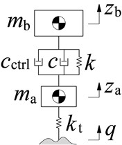
Based on car’s vibration model in Fig. 1, its vibration equations has been described as in Eq. (1):
2.2. Excitations of the car’s model
In order for the MLM to learn FLC’s control rules and effectively control a car’s suspension system under the different operating conditions, a map of the different data of road surfaces should be established. In this study, the different data of road surfaces including the random, bump, and harmonic road surfaces are applied as follows:
Random road surface: According to the ISO-8068 [11], the two road surfaces of level A and B are given as the car’s excitations as follows:
where the spectral density of the road established in a frequency range and speed of cars [4-5], is defined as the random function of white noise with a road’s spatial frequency .
Two types of of random road levels A and B according to the ISO are then chosen and simulated the result. The random road excitation is described as follows:
Bump property of road surface: The bump property of the road surface has been defined by:
where in which is defined as the wavelength of road surface and is the car speed.
Harmonic road surface: The excitation of the harmonic function is given by [11]:
where .
The vibration excitations of the road surface defined in Eqs. (3-5) is then computed and selected as the input values for the model of cars to control the FLC and MLM via the MATLAB/Simulink software.
3. Fuzzy logic control and machine learning method
3.1. Fuzzy logic control
The FLC’s structure includes an fuzzification interface, FIS, and defuzzification interface. The crisp values of FLC is transformed by linguistic variables (LV), then, the fuzzy inference system’s inference rules is applied to solve the if-then of FLC, then, LV is transformed back to crisp values via the physical values to control the system [12-14]. To apply the FLC on the car model, (relative displacement) and (relative velocity) of the car’s suspension are two input data and the is the output value of the FLC. The linguistic variables and FLC’s values have been listed in Table 1, and FLC’s control rules are given in Table 2.
Table 1Linguistic variables and values
LV | LV | (kNs/m) | ||
PB | 0.20 | 0.3 | u0 | 1.0 |
PM | 0.15 | 0.2 | u1 | 1.5 |
PS | 0.10 | 0.1 | u2 | 2.0 |
Z | 0 | 0 | u3 | 2.5 |
NS | –0.10 | –0.1 | u4 | 3.0 |
NM | –0.15 | –0.2 | u5 | 3.5 |
NB | –0.20 | –0.3 | u6 | 4.0 |
Table 2Control rules of the FLC [7]
NB | NM | NS | Z | PS | PM | PB | ||
NB | ||||||||
NM | ||||||||
NS | ||||||||
Z | ||||||||
PS | ||||||||
PM | ||||||||
PB | ||||||||
In Table 1, the linguistic variables are defined by positive big (PB), positive medium (PM), positive small (PS), zero (Z), negative small (NS), negative medium (NM), negative big (NB). Based on the control rules in Table 2, forty-seven rules of if-then in FIS is given as follows:
1. If PB and PB then ;
2. If PB and PM then ;
...
49. If NB and NB then ;
The centroid method of Madani [6, 15] has been used to compute the FIS. Based on the control results of the FLC, the MLM is then used to learn the control rules of the FLC and applied to control the car’s suspension system.
3.2. Machine learning method
The FLC’s effectiveness is only obtained on a condition of the road surface. In the actual operation condition of the cars, the random road surface of ISO levels A or B, or the bump and harmonic road surfaces can randomly appear, thus, the FLC’s effectiveness is limited. Through data maps of different road surfaces and FLC’s logic rules, a learning technique in ANFIS [9, 10] has been then used to control the car’s suspension system, as shown in Fig. 2.
In ANFIS, the input signals a is defined by and an output signal of is:
where are weights, is the trigger function, and is the neural-activation-threshold.
Fig. 2Control algorithm flowchart and computational model
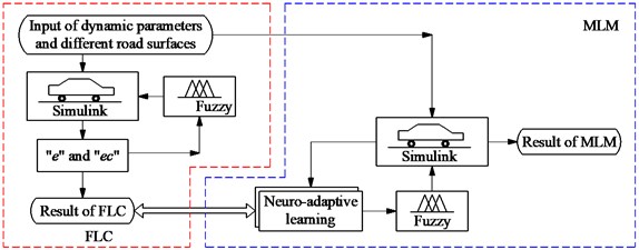
In this study, based on the different road surfaces, control rulers of the FLC, and the car’s model, the data maps of the input signals “ and and output signal are computed. An ANFIS has then applied to calculate the adaptive damping coefficient via the training and machine learning of the MLM [16], shown in Fig. 3(a). Based on the car’s parameters including 282 kg, 45 kg, 17900 (N/m), 165790 (N/m), 1000 (Ns/m), the car’s speed 20 m.s-1, and parameters of the MLM including the number of constituent rules of 3, training method of Hybrid, error of training 10-5, and learning time of 102, the training result has been shown in Fig. 3(b) and it is then applied to MLM to control car’s suspension system model.
Fig. 3Neuro-fuzzy control model and training result
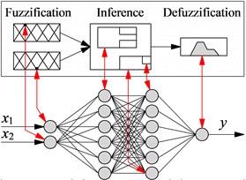
a) Neuro-fuzzy control
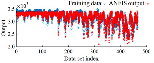
b) Training process result
4. Analysis results
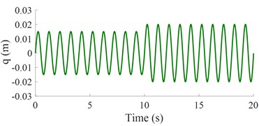
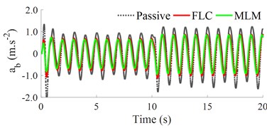
Under random road surface: Based on the car’s operating parameters and the different road surfaces, a random road excitation in Eq. (3) is simulated and plotted in Fig. 4(a). Under the random excitation in Fig. 4(a), the acceleration response of the car’s body is plotted in Fig. 4(b).
The results show that the acceleration response of the vertical car’s body with the FLC and MLM is significantly reduced in comparison with the passive suspension. Besides, the comparison result between the FLC and MLM in the same Fig. 4(b) shows that the acceleration response of the car’s body with the MLM is better than that of the FLC under a simulation condition. This means that the car’s ride comfort using the MLM is significantly improved under the random road surface.
Under a bump road surface: Based on the parameters of the bump road surface 20 m and 0.06 m, a bump road excitation in Eq. (4) is then plotted in Fig. 5(a). Unde this bump road excitation, the acceleration response of the car’s body is then simulated plotted in Fig. 5(b).
Fig. 4Results under a road combination of ISO levels A and B
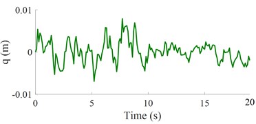
a) The random road surface
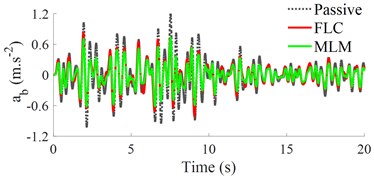
b) Vertical car’s body acceleration response
Fig. 5The control result under a bump road surface
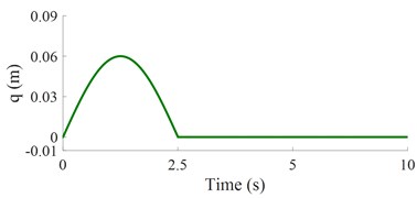
a) The bump road surface
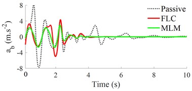
b) Vertical car’s body acceleration response
Fig. 6The control result under a harmonic road surface
a) The harmonic road surface
b) Vertical car’s body acceleration response
The result in Fig. 5(b) also shows that the acceleration response of the vertical car’s body with both the FLC and MLM is smaller than the result of the passive suspension. Additionally, the acceleration response of the vertical car’s body using the MLM is also reduced in comparison with the FLC under the same simulation conditions. Thus, the MLM is good under the bump road surface.
Under a harmonic road surface: Similar, a harmonic road surface of Eq. (5) shown in Fig. 6(a) is also used to simulate and analyze the MLM’s effectiveness. The simulation result of the acceleration response of the car’s body has been indicated as in Fig. 6(b). Observing the result in Fig. 6(b), the acceleration response of the vertical car’s body with the MLM is similar to the simulation conditions of the random and bump road surfaces. It means that the car’s ride comfort with the MLM is better than both the FLC and passive suspension under a simulation condition. Thus, the car’s suspension used the MLM is also effective under a harmonic function.
Via the numerical simulations of MLM under different conditions of cars, it can conclude that MLM has an obvious effect on controlling the car’s ride comfort.
5. Conclusions
Based on map data inputs of different excitations of the road into FLC, the MLM’s effectiveness in improving the car’s ride comfort is better than the FLC under the different simulation conditions.
To have the learning data, the experiment research on the actual road conditions to build FLC’s logic rules need to be done. These problems are difficult to solve. However, through the different data of roads and FLC’s logic rules, MLM in ANFIS could learn the control rule of the FLC to further improve car’s suspension system but without the designer’s experience, and it is the innovation of this study.
This research result is also applied to control the vibration isolation systems of other vehicles such as the heavy trucks, vibratory rollers, and trains.
References
-
Yoshimura T., Isari Y., Li Q., Hino J. Active suspension of motor coaches using skyhook damper and fuzzy logic control. Control Engineering Practice, Vol. 5, Issue 2, 1997, p. 175-184.
-
Pekgökgöz R., Bilgehan M., Kısa M. Active suspension of cars using fuzzy logic controller optimized by genetic algorithm. International Journal of Advances in Engineering Sciences and Applied Mathematics, Vol. 2, Issue 4, 2010, p. 27-37.
-
Félix Herrán L., Mehdi D., et al. Hinf control of a suspension with a magnetorheological damper. International Journal of Control, Vol. 85, Issue 8, 2012, p. 1026-1038.
-
Nguyen V., Jiao, et al. Control performance of damping and air spring of heavy truck air suspension system with optimal fuzzy control. SAE International Journal of Vehicle Dynamics, Stability, and NVH, Vol. 4, 2020, p. 179-194.
-
Wang P., Nguyen V., Zhang J. Experimental research and optimal control of vibration screed system (VSS) based on Fuzzy control. Journal of Vibroengineering, Vol. 22, Issue 6, 2020, p. 1415-1426.
-
Nguyen V., Zhang J., Yang X. Low-frequency performance analysis of semi-active cab’s hydraulic mounts of an off-road vibratory roller. Shock and Vibration, Vol. 2019, 2019, p. 8725382.
-
Wang W., Song Y., et al. An optimal vibration control strategy for a vehicle’s active suspension based on improved cultural algorithm. Applied Soft Computing Journal, Vol. 28, 2015, p. 167-174.
-
Yuan H., et al. Research on semi-active air suspensions of heavy trucks based on a combination of machine learning and optimal fuzzy control. SAE International Journal of Vehicle Dynamics, Stability, and NVH, Vol. 5, Issue 2, 2021, p. 1-14.
-
Jang J., Sun C. Neuro-Fuzzy and Soft Computing: a Computational Approach to Learning and Machine Intelligence. United States Edition, Prentice Hall, 1997.
-
Jang J. ANFIS: Adaptive-network based fuzzy inference systems. IEEE Transactions on Systems, Man, and Cybernetics, Vol. 23, Issue 3, 1993, p. 665-685.
-
Mechanical Vibration-Road Surface Profiles – Reporting of Measured Data. ISO 8068, 1995.
-
Nguyen V., Zhang J. A sensitivity analysis of the importance of the dynamic parameters on the paver’s performance. Journal of Vibroengineering, Vol. 22, Issue 2, 2020, p. 322-336.
-
Hua W., et al. Experimental investigation and vibration control of semi-active hydraulic-pneumatic mounts (SHPM) for vibratory roller cab. SAE International Journal of Vehicle Dynamics, Stability, and NVH, Vol. 5, Issue 4, 2021, p. 1-15.
-
Nguyen V., Wu Z., et al. Vibration analysis and control of vibration screed system of asphalt paver through experimental and simulation. International Journal of Anatomical Variations, Vol. 25, Issue 3, 2020, p. 363-372.
-
Mamdani E. H. Advances in the linguistic synthesis of fuzzy controllers. International Journal of Man-Machine Studies, Vol. 8, Issue 1, 1976, p. 669-678.
-
Fuzzy Logic ToolboxTM User’s Guide, Copyright 1995-2015 by The MathWorks, Inc.
About this article

This work has been supported by the Teaching and Research Project of Hubei Polytechnic University (No. 21xjz04y) and the Key Scientific Research Project of Hubei Polytechnic University (No. 21xjz02A).
