Abstract
In order to increase the lateral stiffness of the joint, a new kind of single-dimensional bidirectional bending joint was developed. Based on the equilibrium analysis of force and moment of the joint and considering the influence of the joint deformation law, the static bending theoretical model of the joint was established. The experimental system was set up to carry out bending experimental. The experimental results show that the experimental data of the joint are consistent well with the theoretical data. The bending deformation has a good consistency of swinging angle from left to right. At 0.35 mPa, the bending angle of the angle reaches 57.5°, which can be used as elbow or knee joints in bionic machinery.
1. Introduction
In recent years, pneumatic flexible joints have many advantages such as light weight, low energy consumption, good compliance and high safety compared with rigid joints, which has been widely applied in various fields such as medical rehabilitation, aerospace and service industries and has become a research hot spot of domestic and foreign scholars [1]. Typical pneumatic actuators include the McKibben artificial muscles [2] and the pneumatic flexible bending joint developed by Zhejiang University of Technology [3]. However, the existing pneumatic actuators cannot fully meet the needs of various bionic robots [4]. In order to solve the current problems, a single dimensional bidirectional bending joint with good flexibility and large lateral stiffness was designed. The bending characteristics of the joint are studied by combining theory with experiment, which laid a foundation for later research.
2. Structure and function of flexible joint
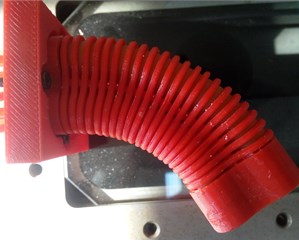
The joint is composed of upper and down cover, constrain components, latex tubes and a spring plate, which is shown in Fig. 1. Latex tube, constrain components and the plug form a good seal cavity called artificial muscle. The joint is equivalent to four artificial muscles in parallel with a spring plate, with one degree of freedom. The spring plate is the center frame, which is connected with the upper and down cover by bolt-nut. The restraint ring (Fig. 2) is provided with a 1 mm convex platform, which is mainly used to increase the deformation capacity of the joint.
When compressed gas is injected into the joint, the external restraint ring limits the radial deformation of latex tubes, the joint is only subject to the axial force and resultant torque generated by the gas, which is shown in Fig. 3(a). Due to the large axial stiffness of spring plate, it can be assumed that the axial elongation is zero so that the joint only occur bending deformation around the spring plate. The biggest feature of the joint is that two muscles on the same side drive at the same time. Therefore, when the 1 and 2 muscles are ventilated, the joint is bending in the direction of the 3 and 4 muscles. Similarly, when the 3 and 4 muscles are ventilated, the joint is bending in the direction of the 1 and 2 muscles. Therefore, bilateral muscle alternate ventilation can achieve one-dimensional joint active bending in both directions.
Fig. 1Three-dimensional model
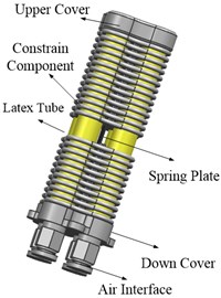
Fig. 2The structure of restraint ring
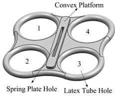
Fig. 3The deformation mechanism of joint
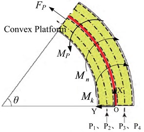
a) Force analysis of the joint
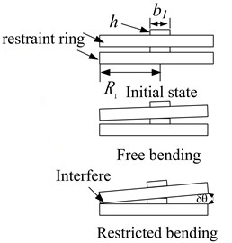
b) Deformation process between adjacent constraint rings
3. Bending model of the flexible joint
According to the structure characteristics of the joint, the bending model can be divided into two cases: One is the free bending model. The other is that the deformation and bending reach the limit when constraint rings interferes, which is shown in Fig. 3(b).
For the first case, the bending angle can be modified according to the theoretical model of dual-drive unidirectional bending joint [5]:
where is the bending angle of the joint, is the working air pressure and the value range is 0 to 0.35 MPa, 11 mm is outer diameter latex tube, 8 mm is inner diameter latex tube, 60 mm is effective deformation length of the joint, 8 mm is the distance from the center line of latex tubes to the neutral layer, 0.25 mm is the thickness of spring steel plate, 12 mm is the short side length of spring plate, 206 GPa is shear modulus of spring plate, 1.367 MPa is shear modulus of latex tube, 5.174×10⁻¹⁰ m4 is the cross section moment of inertia of the muscles, 0.3 is Poisson’s ratio.
For the second case, the bending angle can be obtained according to the geometric knowledge:
where is the bending angle of the joint when adjacent restraint rings interfere, 1 mm is the height of convex platform, 2.7 mm is the width of the convex platform, 16 mm is the radius of the constraint ring.
4. Deformation experiments and analysis
4.1. The experimental method
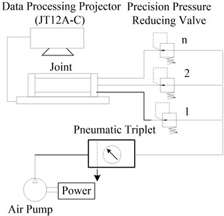
Experimental principle diagram of bending deformation is shown in Fig. 4. The experimental system consists of two parts: pneumatic control system and data measurement system. The pneumatic control system is mainly composed of air source, pneumatic triplet, precision pressure reducing valve. The data measurement system mainly consists of data processing projector.
Fig. 4The principle of experiment
4.2. Analysis of experiment
Fig. 5 is the comparison curve between theoretical data and experimental data. The comparison curve of the left-right swing angle of the joint is shown in Fig. 6. Fig. 7 is the swing posture of the joint at 0.35 MPa.
Fig. 5Bending deformation contrast curve of the joint
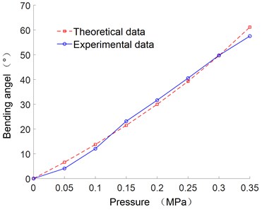
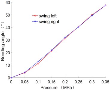
Fig. 6Relationship between bending angle and air pressure
As can be seen from Fig. 5, the deformation of joint is increase with the increase of the air pressure. The error between the theoretical and experimental curve is small, which verify the correctness of the theoretical formula.
It can be seen from Fig. 6 that the angle error of the joint swing from left to right is small. When the air pressure is 0.35 MPa, the bending angle reaches 57.5°.
Fig. 7Swing posture of the joint
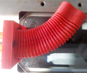
a) Swing left
b) Swing right
The polynomial fitting method was adopted to obtain the empirical formula between the joint bending angle and air pressure. Due to the complexity of the theoretical model, the empirical formula can be used as the mathematical model to control the deformation:
where is the bending angle of the joint, is the air pressure.
The above fitting formula can be used to simulate the displacement change curves of the characteristic points at different positions on the center line of joint deformation under different pressures, which is shown in Fig. 8.
Fig. 8Relationship between bending angle and air pressure
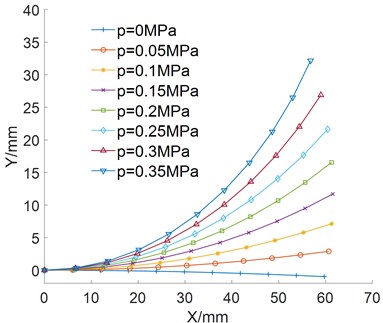
It can be seen from Fig. 8 that the bending deformation is smooth, harmonious and approximates a circular shape.
5. Conclusions
In this paper, a new kind of single dimensional bidirectional bending flexible joint is developed. Firstly, the principle of bending deformation is described based on the structural of the joint. And then bending model of the joint is established and verified by experiments. Experimental results show that the bending angle increase with the increase of air pressure. In addition, the joint swings from left to right has a good consistency. The bending angle reaches 57.5° when the air pressure is 0.35 MPa and the bending deformation is smooth and harmonious, which can be used as elbow or knee joints.
References
-
Haraguchi D., Tadano K., Kawashima K. Development of a pneumatically-driven robotic forceps with a flexible wrist joint. Procedia CIRP, Vol. 5, 2013, p. 61-65.
-
Chen D. H., Ushijim K. Prediction of the mechanical performance of McKibben artificial muscle actuator. International Journal of Mechanical Sciences, Vol. 78, 2014, p. 183-192.
-
Wang Zhiheng, Qian Shaoming, Yang Qinghua, et al. Pneumatic robot multi-finger dexterous hand-ZJUT hand. Robot, Vol. 34, Issue 2, 2012, p. 223-230.
-
Choi H. R., Jung K., Ryew S., et al. Biomimetic soft actuator: design, modeling, control, and applications. IEEE/ASME Transactions on Mechatronics, Vol. 10, Issue 5, 2005, p. 581-593.
-
Liu Hongbo, Geng Dexu, Zhao Yunwei, et al. Bending characteristics of single bending flexible joint with dual drive. Journal of Beihua University (Natural society), Vol. 18, Issue 6, 2017, p. 815-819.
About this article

The authors would like to thank the Jilin Province Science and Technology Development Program of Jilin Province No. 20170204064GX and No. 20180201050GX, Project of Education Department of Jilin Province No. JJKH20190541KJ.
