Abstract
In this paper, the dynamic behavior of the slider-crank mechanism with clearance fault is investigated. The revolute joint with clearance is equivalent to a virtual massless rod, and then the dynamic equation of the crank slider mechanism with clearance is established by the Lagrangian method. In addition, a three-dimensional dynamic model of the crank slider mechanism with clearance is also established by ADAMS. The numerical results show that the clearance affects the displacement and velocity response of the crank-slider mechanism in a weak way, but influences the acceleration response of the mechanism in a significant manner. Due to the existence of the clearance, the revolute joint of the mechanism produces a rub-impact phenomenon, and the larger the clearance, the greater the impact strength. During the rub-impact process, there are three kinds of motion states of separation, collision and contact occur.
Highlights
- Dynamic model of the slider-crank mechanism with clearance fault is established by Lagrangian method based on continuous contact state.
- The clearance fault has the greatest influence on the acceleration response, and has the least influence on the displacement response in the slider-crank mechanism.
- The numerical simulation results show that the clearance influences the dynamic performance of the slider-crank mechanism, and will cause the mechanism to produce severe vibration and shock.
1. Introduction
Slider-crank mechanism is a typical reciprocating mechanical system that includes a plurality of revolute joints and translational joints. In the actual project, the movement clearance is inevitable, the main reasons are three aspects: First, in order to realize the rotation hinge and the sliding hinge movement, the regular assembly clearance is reserved in the design. Second, there are inevitable precision errors in the design and manufacture of various joint components. Third, the irregular clearance caused by the wear of the motion pair itself [1]. Obviously, regardless of the clearance, the dynamic characteristics of the rub-impact of the slider-crank mechanism are adversely affected.
In recent years, a small number of scholars have carried out research on the rub-impact dynamic characteristics of the slider-crank with clearance fault. For the mechanism members are rigid and do not consider lubrication, Flores et al. [2] proposed a general method for multi-body dynamics modeling and analysis for revolute joints with multi-clearance. In the study, a continuous contact force model based on elastic Hertz theory and dissipative terms was established, in which the actual joints affected by geometric and physical properties were considered as collision bodies. The results of the study indicated that clearance size and working conditions play a crucial role in accurately predicting the dynamic response of the system. For the non-lubrication of the revolute joint with clearance, considering the elastic deformation of the rod, Zheng et al. [3, 4] studied the dynamic characteristics of the rigid-flexible coupling slider- crank mechanism, and analyzed the influence of the clearance size, the crankshaft speed and the number of clearances on the dynamic response. In addition, Bauchau et al. [5] established the nonlinear dynamic equations of flexible multi-body systems with clearances, and discussed the influence mechanism of clearance and flexibility factors on the dynamic response of the mechanism. For the frictional situation considering the lubrication, Alshaer et al. [6], Flores et al. [7-9], Tian et al. [10-12], Zheng et al. [13] explored the dynamics analysis method for lubricating revolute joint and the ball joint with clearances, and calculated the rub-impact contact force under the action of lubrication using the fluid dynamics theory. The numerical results showed that compared with the dynamic characteristics of the lubrication clearance model, the frictional contact force without lubrication can cause the system to generate stronger fluctuation peaks. In order to reduce the adverse effects of the revolute joint with clearance, Varedi [14] proposed a method based on particle swarm optimization to optimize the mass distribution of the mechanism to reduce or eliminate the impact force at the joint with clearance. Finally, the effectiveness of the algorithm is verified by an example.
2. Dynamic model
2.1. Dynamic model based on continuous contact state
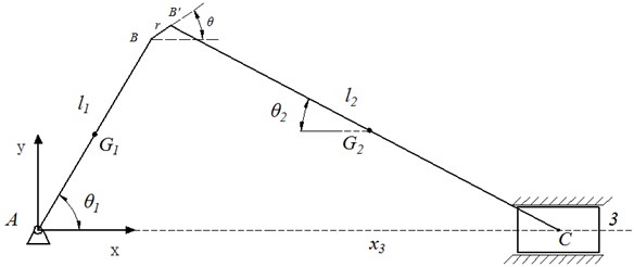
Assume that there is an excessive clearance at the revolute joint B between the crankshaft and the connecting rod in the crank slider mechanism shown in Fig. 1. Considering that the clearance at the revolute joint B is very small, the collision and contact time of the moving side elements are very short, so it is assumed that the moving joints are always in contact state, and the collision and separation are completed instantaneously. By simplifying and ignoring the elastic deformation and damping of the contact surface of the moving joints, the clearance is equivalent to a virtual rigid rod of the same size. When the mechanism has a sudden change in a certain azimuth at work, it is considered that the moving joints are in a separated state. After the equivalent of the clearance model, the mechanism evolves into a multi-bar multi-degree-of-freedom system, and the Lagrangian equation can be used to establish the dynamic equation of the system. The second type of Lagrangian equation is expressed as follows:
where and represent the sum of the kinetic energy and potential energy of the slider-crank mechanism, respectively. is the generalized force.
Since the system shown in Fig. 1 has only one degree of freedom, a generalized coordinate should be introduced. Eq. (1) will evolve into Eq. (2):
where, is the generalized coordinate introduced. It is not difficult to find that the expression of the sum of the kinetic energy of the crankshaft, the connecting rod and the slider is as follow:
where , , and are the masses of the crankshaft, connecting rod, and slider, respectively. , are the lengths of the crankshaft and the connecting rod, respectively. , , and represent the angle between the crankshaft, the link, the virtual rod and the -axis, respectively.
Similarly, the sum of the potential energy of the crankshaft, the connecting rod and the slider can be obtained as follow:
Substituting Eqs. (3) and (4) into Eq. (2) yields an expression:
Fig. 1Schematic diagram of the slider-crank mechanism with clearance fault
Substituting Eqs. (3) and (4) into Eq. (2) yields an expression:
where:
2.2. Three-state dynamic model
In this paper, A three-state based dynamics model was adopted by the ADAMS software. In the ADAMS, the clearance rub-impact is characterized by establishing a contact force model. The contact force model is written as follow:
where is used to calculate the distance between the points in the two geometric objects that will make contact. ̇ is the time derivative of , which is the collision or separation velocity. is the free length of , that is, when , there is penetration between two geometric objects, the contact force is positive, otherwise it is equal to zero. is the stiffness of the contact surface, depending on the nature of the material at the contact and the contact radius. represents the index of elastic force. is the maximum viscous damping coefficient. is the upper boundary of penetration corresponding to .
In this paper, IMPACT can be defined the following expression:
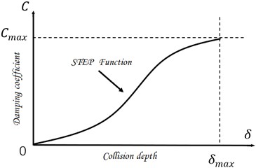
where is a step function that uses a cubic polynomial approximation to calculate the viscous damping coefficient, which avoids the case where the viscous damping coefficient is not zero when the penetration is zero, as shown in Fig. 2:
where, when is positive, the definition is the maximum, and the reasonable parameter is 0.0l mm.
Fig. 2STEP function
3. Results and discussions
Rub-impact of the revolute joint with clearance will inevitably affect the dynamic behavior of the slider-crank mechanism, and how its influence law evolves is the research content of this section. In the simulation, the dimensions of the slider-crank mechanism are as follows: The crankshaft is a steel rod of 1000 mm×100 mm×50 mm, the connecting rod is a steel rod of 2000 mm×100 mm×50 mm, and the slider is a steel cube of 500 mm×500 mm×500 mm. The crankshaft rotates at a constant speed of 30 rad/s.
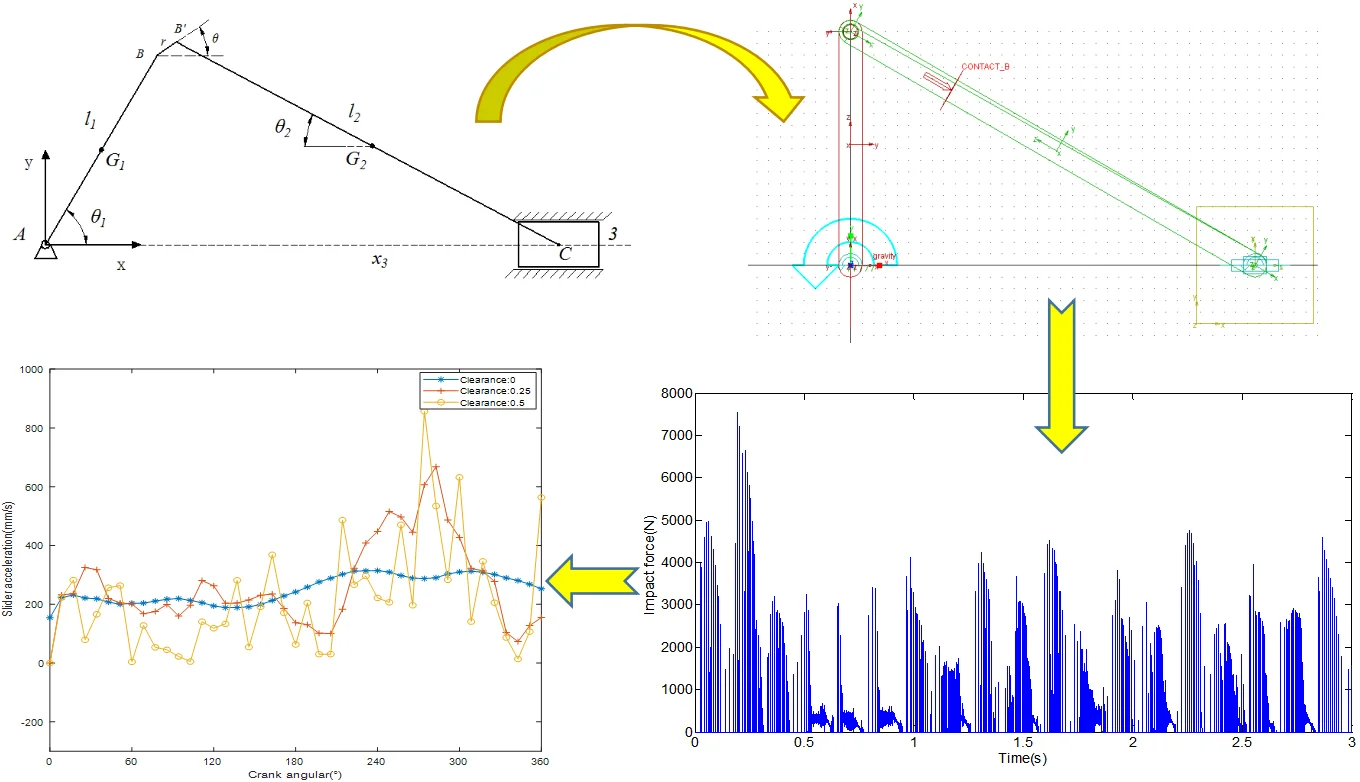
In the ADAMS software, the dynamic model of the created slider-crank mechanism with clearance fault is shown in Fig. 3. Through numerical simulation, the output responses of the displacement, velocity and acceleration of the slider-crank mechanism are shown in Figs. 4, 5 and 6, respectively. From Fig. 4, as the clearance size increases, the displacement response curve of the slider remains smooth, indicating that the displacement response is substantially unaffected by the clearance. As can be seen Fig. 5, as the clearance size increases, compared with the displacement response curve, the velocity response curve has significant fluctuations, indicating that the clearance has a greater influence on the velocity than the displacement. When the crankshaft angle is 120°, as the clearance increases from 0 mm, 0.25 mm to 0.5 mm, the corresponding velocity increases from 0 mm/s, 60 mm/s to 180 mm/s. In Fig. 6, In sharp contrast with the displacement and velocity response curve, the acceleration response curve of the slider will become more and more severe, and the range of fluctuations is getting wider and wider. When the crank angle is 250°, as the clearance increases from 0 mm, 0.25 mm to 0.5 mm, the corresponding velocity increases from 220 mm/s², 600 mm/s² to 850 mm/s².
It is not difficult to see that, from the degree of influence, the clearance fault has the greatest influence on the acceleration response, and has the least influence on the displacement response in the slider-crank mechanism.
Fig. 3The dynamic 3D model
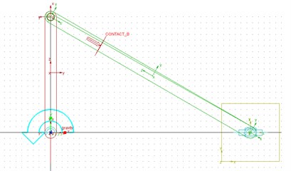
Fig. 4Displacement response curve
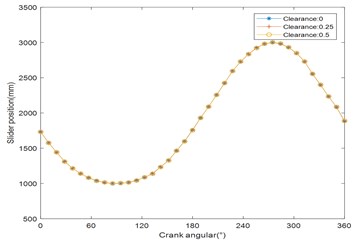
Fig. 5Velocity response curve
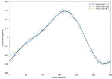
Fig. 6Acceleration response curve
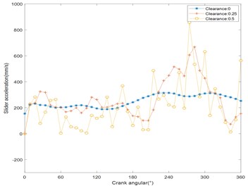
Fig. 7Rub-impact force for 0.5 mm clearance
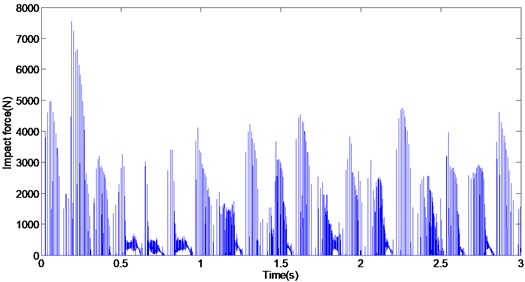
Fig.7 shows the rub-impact contact force for 0.5 mm clearance in the slider-crank mechanism. In Fig. 7, we can observe three motion states of the revolute joint, including impact, separation, and contact state. Obviously, the rub-impact force will affect the dynamic performance of the slider-crank mechanism, and cause the crank slider mechanism to produce severe vibration and impact.
4. Conclusions
In this work, the dynamic behavior of the slider-crank mechanism with clearance fault is discussed. The dynamic model of the slider-crank mechanism with clearance in continuous contact state is established by the Lagrangian method. At the same time, a three-dimensional dynamic model was established using ADAMS software. The numerical analysis results show that the clearance influences the dynamic performance of the slider-crank mechanism and will cause the mechanism to produce severe vibration and shock. The influence of displacement, velocity and acceleration response of the mechanism with clearance increase in turn, and the larger the clearance, the greater the influence.
References
-
Flores P., Ambrósio J., Claro J., Lankarani H. Kinematics and Dynamics of Multibody Systems with Imperfect Joints: Models and Case Studies. Berlin, 2007.
-
Flores P. A parametric study on the dynamic response of planar multibody systems with multiple clearance joints. Nonlinear Dynamics, Vol. 61, Issue 4, 2010, p. 633-653.
-
Zheng E., Wang T., Guo J., et al. Dynamic modeling and error analysis of planar flexible multilink mechanism with clearance and spindle-bearing structure. Mechanism and Machine Theory, Vol. 131, 2019, p. 234-260.
-
Zheng E., Zhou X. Modeling and simulation of flexible slider-crank mechanism with clearance for a closed high speed press system. Mechanism and Machine Theory, Vol. 74, 2014, p. 10-30.
-
Bauchau O. A., Rodriguez J. Modeling of joints with clearance in flexible multibody systems. International Journal of Solids and Structures, Vol. 39, Issue 1, 2002, p. 41-63.
-
Alshaer B. J., Nagarajan H., Beheshti H. K., Lankarani H. M. Dynamics of a multibody mechanical system with lubricated long journal bearings. Journal of Mechanical Design, Vol. 127, Issue 127, 2005, p. 493-498.
-
Flores P., Ambrósio J., Claro J. C. P., Lankarani H. M., Koshy C. S. A study on dynamics of mechanical systems including joints with clearance and lubrication. Mechanism and Machine Theory, Vol. 41, Issue 3, 2006, p. 247-261.
-
Flores P., Ambrosio J., Claro J. C. P., Lankarani H. M., Koshy C. S. Lubricated revolute joints in rigid multibody systems. Nonlinear Dynamics, Vol. 56, Issue 3, 2009, p. 277-295.
-
Flores P., Lankarani H. M. Spatial rigid-multibody systems with lubricated spherical clearance joints: modeling and simulation. Nonlinear Dynamics, Vol. 60, Issues 1-2, 2010, p. 99-114.
-
Tian Q., Zhang Y., Chen L., Flores P. Dynamics of spatial flexible multibody systems with clearance and lubricated spherical joints. Computers and Structures, Vol. 87, Issues 13-14, 2009, p. 913-929.
-
Tian Q., Liu C., Machado M., Flores P. A new model for dry and lubricated cylindrical joints with clearance in spatial flexible multibody systems. Nonlinear Dynamics, Vol. 64, Issues 1-2, 2011, p. 25-47.
-
Tian Q., Sun Y., Liu C., Hu H., Flores P. ElastoHydroDynamic lubricated cylindrical joints for rigid-flexible multibody dynamics. Computers and Structures, Vol. 114, 2013, p. 106-120.
-
Zheng E., Zhu R., Zhu S., Lu X. A study on dynamics of flexible multi-link mechanism including joints with clearance and lubrication for ultra-precision presses. Nonlinear Dynamics, Vol. 83, Issues 1-2, 2016, p. 137-159.
-
Varedi S. M., Daniali H. M., Dardel M. Dynamic synthesis of a planar slider-crank mechanism with clearances. Nonlinear Dynamics, Vol. 79, Issue 2, 2015, p. 1587-1600.
About this article

This paper was supported by the following research projects: by the Special Project of Ningde Normal University in 2018 (Grant No. 2018ZX409, Grant No. 2018Q102, Grant No. 2018ZX401) and Research project for Yong, Middle-aged Teacher in Fujian Province (Grant No. JT180601 and Grant No. JT180597). These supports are gratefully acknowledged.
