Abstract
This study proposes a combined method of the multi-body system theory and the Jourdain’s principle to study the automotive vibration. A 3D dynamic model of the automotive is built based on the multi-body system theory, the vibration equations are described based on two methods including a method of the Jourdain’s principle and the traditional method of the Newton-Euler’s principle. Matlab/Simulink software is used to solve the vibration equations under the excitation of the step road. The results show that the acceleration responses of the vertical, pitch and roll vibrations of the vehicle’s body with the Jourdain’s method are similarly in comparison with the traditional method. Therefore, the Jourdain’s method not only is applied for studying the kinetic and dynamic model of multi-body systems but also can be applied for studying the automotive vibration. Especially, nonlinear properties of objects in the vibration model can be clearly described by the Jourdain’s method via the recursive Jacobian matrices.
1. Introduction
In order to establish the mathematical equations from the physical models of the multi-body systems, there were many methods for establishing the equations describing the motion of the system, such as Euler-Lagrange and D’Alembert’s principle [1, 2], Newton-Euler equations [3], Hamilton’s principle, Jourdain’s principle combines with multi-body system theories [4, 5].
Automotives are also considered to be multi-body systems including seats, vehicle body, engine, axles and wheels. Multi-bodies are connected through vibration isolation mounts. In the study of the automobile vibrations, two main methods were used including (1) using Adams, CATIA softwares to establish 3D models, the models were then simulated and analyzed the objectives via ANSYS or Matlab software [3, 6], and (2) from an actual automotive, establishing the physical model, the vibration equations were then established based on D’Alembert’s principle or Newton-Euler equations. Matlab/Simulink software was used to calculate the objectives [2, 7]. However, the second method was almost applied for study the automotive vibrations due to the efficiency of method for analyzing nonlinear models. Besides, a traditional method of the Newton’s second law not only simply used to establish vibration equations for simple physical models but also applied for solving nonlinear systems was almost chosen to establish the vibration equations of the car [3], the bus [8], the heavy truck [9], the vibratory roller [7], and so on. However, this method is difficult to apply for the complex dynamic systems of automotives considering the strong nonlinear force components such as the interactive of the wheels with the road surface, the characteristic of the suspension system when considering the impact of the suspension with the limiting stopper, wheel off-road surface.
Kinetic relationships of the complex dynamic systems are often expressed via trigonometric functions, which are factors that cause nonlinear. If the trigonometric angles are changed to be small in the wide range, the kinetic relations are strongly nonlinear. For these problems, the Jourdain’s principle (JP) was applied to establish the equations. Based on the multi-body system theory, a motorcycle dynamic model using JP was used to study the lateral stability of motorcycles [4]. The results showed that the longitudinal/vertical motions of the model were easily determined via kinetic relationships and the trigonometric functions. In addition, the derivation of the equations of motion from JP was similar independence in comparison with Lagrange’s principle which was used for establishing the vibration equations [5]. However, the JP has not yet been applied to study the automotive vibration.
In this study, a modified technique for studying the automotive vibrations based on a combined method of the multi-body system theory and the JP is applied. The nonlinear dynamic model of the vehicle is established based on two methods of the JP and the Newton’s second law. Matlab/Simulink software is used to simulate and compare the results of two methods under a step excitation of the road. The major goal of this study is to provide a modified technique for studying the automotive vibration apart from the traditional methods.
2. Methods for study the automotive vibration
2.1. Jourdain’s principle
Assuming that the kinematics of the mechanical system are characterized by generalized velocities corresponding to natural coordinates . Therefore, the linear and angular velocity and the linear and angular acceleration of each body th in moving reference with respect to the inertial reference can be expressed by [5]:
The JP called by the principle of the virtual power is defined by [4]: Jourdain’s principle states that the virtual power done by motion compatible constraint efforts / is null, then:
Appling Newton-Euler’s equation for motion compatible constraint efforts /, we have:
By replacing Eqs. (2), (4) into Eq. (3), and after some algebraic manipulations, the dynamics motion expression is deduced as following:
where is the mass matrix obtained by the direct calculation of Jacobian matrices; is the vector of the generalized efforts.
2.2. Applying Jourdain’s principle for study the automotive vibration
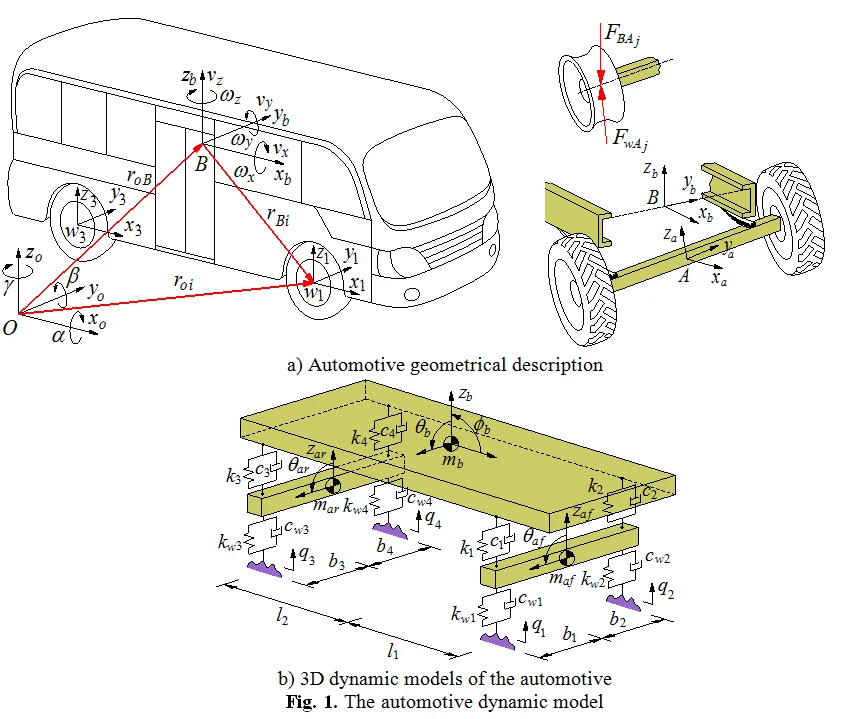
The automotive model is considered as a set of seven bodies including the main body , the front axle , the rear axle and the four wheels . A direct application of the JP to establish the vibration equations of the vehicle is exposed. For this, the kinematics of each body in the moving reference is described as follows: The generalized coordinates at the centre of gravity of the main body are (the generalized coordinate ), of the each axle is (the generalized coordinate ), and of each wheel is (the generalized coordinate ), (, ; 1-4), as plotted in Fig. 1(a). Assuming that the moving reference is at the generalized coordinate , three natural coordinates at the centre of gravity of the main body are the vertical displacement , the pitch and roll angles corresponding to its three generalized velocities are , and , respectively. Besides, two natural coordinates of the front and rear axles including vertical displacement and the roll angle at the centre of gravity of each axle also are and corresponding to two generalized velocities are and . Hence, the generalized coordinates and velocities of the body and the axles are respectively defined by:
The motion of wheels is considered as excitation forces that affect the suspension system and the vehicle body causing vibration of the automotive.
Fig. 1The automotive dynamic model
a) Automotive geometrical description
b) 3D dynamic models of the automotive
The mass matrix of the main body : The mass matrix is calculated via the automotive model in Fig. 1(a) as follows:
In the inertial reference , the linear and angular velocity of the main body is given by:
where , , and are the direction vectors; is the static height of the centre of gravity of the vehicle body.
By replacing Eq. (7) into the mass matrix of the main body in Eq. (5), and after some algebraic manipulations, we have:
where , and are the mass and the mass moments of inertia for the body pitch and roll.
The mass matrix of the axles : The position of the axle th with respect to the inertial reference are obtained by . The linear and angular velocity of each axle th in moving reference is obtained by a direct differentiation as:
where and are the direction vectors of vertical and roll motions.
By replacing Eq. (9) into the mass matrix of the axles in Eq. (5), we have:
Vector of generalized efforts : Assume that is the dynamic reaction forces from each axle into the vehicle body via the suspension systems and is the dynamic reaction forces of each wheel, we have:
where and are damping and stiffness coefficients, and is the relative displacement of the suspension systems; and are damping and stiffness coefficients of each wheel; is the deformation of each wheel; is the exciting vibration from the road, ( 1-4).
Vector of generalized efforts of the main body : The dynamic reaction force is determined by the vector of the generalized force and generalized moment as follow:
The linear and angular velocity of the main body in moving reference are obtained by:
Replacing Eqs. (11), (13) into the vector of the generalized effort in Eq. (5), we have:
where 1-2 then 1, 3-4 then 2; is the distance from the position of to the centre of gravity of the main body; is the gravitational acceleration of the main body and it is calculated by , in which is the matrix rotation of the body pitch and roll rotations in moving reference and it is described in the reference [4].
Vector of generalized efforts of the axles : In the automotive model, the vehicle floor and the axles are connected by the dependent suspension systems. Therefore, the dynamic reaction forces affected on each axle is determined by:
The linear and angular velocities at each wheel and at the centre of gravity of each axle are:
Replacing Eqs. (11), (12), (16) into the vector of the generalized efforts in Eq. (5), the vector of generalized efforts of the front axle and rear axle in Eq. (15) is determined by:
where is the gravitational acceleration of each axle in moving reference calculated by ; described in the reference [4] is the matrix rotation of the front and rear axles in the axle roll rotation depended on the structure of the dependent suspensions.
By replacing Eqs. (6), (8), (14) into Eq. (5), and also replacing Eqs. (6), (10), (15) into Eq. (5), the dynamics motion expressions of the main body and the axles are deduced by:
The Eq. (18) is the general dynamic differential equations for the vehicle vibration model based on the Jourdain’s method.
2.3. Traditional method for study the automotive vibration
A 3D vehicle dynamic model is established as in Fig. 1(b). Based on Newton’s second law is applied to establish the vibration equations. The general dynamic differential equations for the vehicle model are then given by the following matrix form:
where [], [] and [] are (×) mass, damping and stiffness matrices; and are the (×) displacement vector and exciting force vector; and is the number of DOF, ( 7).
3. Simulation results and comparisons
In order to compare between the traditional and Jourdain’s methods for study the automotive vibration, an excitation of the step road carried out in Fig. 2 at a speed 20 m.s-1 of the vehicle traveling and the automotive parameters in the reference [10] are chosen to simulate. The simulation results of the acceleration responses with two methods are plotted in Fig. 3.
Observing Figs. 3, it can see that the acceleration responses of the vertical, pitch and roll vibrations of the vehicle body with the Jourdain’s method are similarly in comparison with the traditional method, especially the acceleration responses at 1.0-1.5 s, as see in Fig. 3(a) and (b). Also, at very small acceleration region from 1.5 s to the end, the acceleration responses with the Jourdain’s method are lightly deviated in comparison with the traditional method. This may be due to the effect of the Jacobian matrices which is characterized by the vibration equations of the JP. This characteristic reflects the strong or weak nonlinear properties of the dynamic model and its vibration equations, and it is clearly shown in Fig. 3(c). Fig. 3(c) shows that the acceleration response of the vehicle body’s roll angle with the traditional method is approximately zero value. This is due to the automotive dynamic model symmetrically assumed in the vertical plane, and the excitations of the left/right wheels are the same, as seen in Fig. 1(b). However, it is clearly with the Jourdain’s method, especially at 1.0 to 1.5 s. Although the acceleration value is also very small, but the result shows that the nonlinear characterizes of the dynamic model with the Jourdain’s method are clearly in comparison with the traditional method. Therefore, the Jourdain’s method not only can be applied for studying the automotive vibration but also can clearly reflect the strong or weak nonlinear properties of the automotive dynamic model.
Fig. 2Time history of the excitation road sources
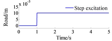
Fig. 3The accelerations responses on a step road
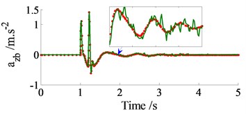
a) Vertical vehicle body
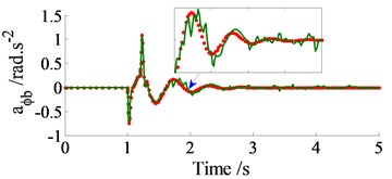
b) Vehicle body’s pitch angle
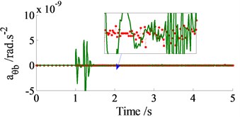
c) Vehicle body’s roll angle

4. Conclusions
The comparison results of the acceleration responses with two methods are similarly under the excitation of the step, therefore, the method of the Jourdain’s principle can be applied to research the automotive vibrations apart from the traditional methods. The Jourdain’s method clearly reflects the strong or weak non-linear properties of the dynamic model through the vibration equations with recursive Jacobian matrices. This is very significant for studying the vibration of the complex dynamic models of the automotive with strong nonlinear properties.
References
-
Temmerman J., Deprez K., Anthonis J., Ramon H. Conceptual cab suspension system for a self-propelled agricultural machine, part 1: development of a linear mathematical model. Biosystems Engineering, Vol. 89, Issue 4, 2004, p. 409-416.
-
Prentkoviskis O., Bogdevicius M. Dynamics of motor vehicle taking into consideration the interaction of wheels and road pavement surface. Transport, Vol. 17, Issue 6, 2002, p. 244-253.
-
Ieluzzi M., Turco P., Montiglio M. Development of a heavy truck semi-active suspension control. Control Engineering Practice, Vol. 14, 2006, p. 305-312.
-
Nehaoua L., Nouvellière L., Mammar S. Dynamics modeling of a two-wheeled vehicle using Jourdain’s principle. 19th Mediterranean Conference on Control and Automation (MED), Corfu, Greece, 2011.
-
Papastavridis J. On Jourdain’s principle. International Journal of Engineering Science, Vol. 30, Issue 2, 1992, p. 135-140.
-
Zehsaz M., Sadeghi M., et al. Tractor cabin’s passive suspension parameters optimization via experimental and numerical methods. Journal of Terramechanics, Vol. 48, 2011, p. 439-450.
-
Liem N. V., Run Z. J., et al. Vibration analysis and modeling of an off-road vibratory roller equipped with three different cab’s isolation mounts. Shock and Vibration, Vol. 2018, 2018, p. 8527574.
-
Sekulic D., Dedovic V. The effect of stiffness and damping of the suspension system elements on the optimisation of the vibrational behaviour of a bus. IJTTE, Vol. 1, Issue 4, 2011, p. 231-244.
-
Tsampardoukas G., Stammers C., et al. Hybrid balance control of a magnetorheological truck suspension. Journal of Sound and Vibration, Vol. 317, 2008, p. 514-536.
-
Dang Viet Ha Influence of Structural Parameters and Operating on Vietnam’s Bus Ride Comfort. Ph.D. Thesis, Hanoi University of Science and Technology, Vietnam, 1996.
About this article

The work described in this paper was supported by Thai Nguyen University of Technology for an International Joint Scientific Project (Code: T2016-LK01).
