Abstract
In this work we present an optical accelerometer based in a cantilever beam attached to a fiber Bragg grating (FBG), which can be applied to the seismic and geological fields. This device main characteristics are a high strain along the FBG and a wide operational frequency range. The accelerometer can be easily modeled as a mass block and a fiber optic attached at the cantilever beam tip, the FBG length varies due to the movement of the mass caused by the vertical vibrations. The frequency response range has been enhanced and it was achieved a natural frequency of 242.4 Hz.
1. Introduction
The accelerometers nowadays are widely used to measure vibrations, seismic monitoring, stabilize platforms, tilts, etc. The fiber Bragg grating (FBG) accelerometers, in particular, are a growing field of research and applications because they possess several advantages over the conventional electrical accelerometers such as immunity to electromagnetic interference (EMI), radio frequency interference (RFI), multiplexing capability, higher sensitivity, low noise and the possibility to implement sensor networks [1-3].
We propose a simple modification related to the FBG mounting technique on a cantilever beam in order to increase the sensitivity, compared to conventional FBG based cantilever-mass accelerometers, where a FBG attached to the tip of the cantilever and elongate the fiber length due to the movement of the mass. Through a designed mechanical structure, the FBG sensor converts the vibration into strain signal and this structure owns a higher frequency compared with the civil engineering field.
2. Theoretical basis of sensitivity enhancement
From the optical accelerometer mechanical structure, in Fig. 1, it can be described the maximum cantilever deflection by analyzing the cantilever-mass as a nonprismatic beam and the FBG axial strain by using the pure bending theory, as previously described by Casas-Ramos and Sandoval-Romero (2015) [4]. Fig. 1 shows the cantilever and the mass block at its tip as sections of a single mechanical piece; Table 1 shows the variables, values and descriptions (values taken from [4]). And from the cantilever deflection and FBG axial strain, it can be found device the natural frequency.
The maximum deflection occurs at the tip of the beam, therefore there is a maximum deformation due to the beam bending. The FBG fixed between points A (mass block) and D (sensor’s shell). The force counts the acceleration of gravity 1, 9.81 m/s2.
The maximum deflection was calculated from the structure geometry, by applying the method of the superposition [5] Fig. 2. The deflection in the section AC (mass block) shows that the mass block is held rigidly at point C and neither deflects nor rotates at this joint. The deflection in the section AC is represented with :
where /12 and . The bending section CB behaves as cantilever beam and contributes to the maximum deflection at A. In the point C the part is subjected to a concentrated load , and results in a deflection and an angle of rotation at the free end:
where /12. The deflection and rotation angle make an additional contribution to to the maximum deflection . The displacement equals to the following:
Table 1Device dimension parameters, from [4]
Parameter | Value | Description |
29.27 mm | Cantilever length | |
16.33 mm | Mass block length | |
19.43 mm | Length of the attached fiber | |
1 mm | Cantilever height | |
24.89 mm | Mass block height | |
16.42 mm | Width of the cantilever and mass block | |
18.69 g | Mass block weight | |
2800 kg/m3 | Aluminium 7075 density | |
72 GPa | Aluminium 7075 Young modulus | |
16.56 GPa | Fiber optic SMF-28e Young modulus | |
47.14 nm2 | Transversal fiber optic SMF-28e area |
Fig. 1Device structural schematic, from [4]
![Device structural schematic, from [4]](https://static-01.extrica.com/articles/20379/20379-img1.jpg)
Fig. 2Cantilever beam deflection analysis, from [4]
![Cantilever beam deflection analysis, from [4]](https://static-01.extrica.com/articles/20379/20379-img2.jpg)
The final resulting deflection at the tip of the beam (point A) equals to the sum of deflections and :
By using the pure bending theory [5-7], it is known that the beam and the FBG have the flexibility of a spring and can easily be determined from the elongation produced by a known load , the spring constant for each one is:
where is the spring constant to the beam and corresponds to the FBG spring constant. Thus, the natural frequency can be given from the angular natural frequency in:
And by substituting the Table 1 parameters in Eq. (8) this gives a theoretical natural frequency of 237.5 Hz. The given natural frequency value is because the device was designed to maximize the strain along the FBG due to the vertical acceleration.
Fig. 3(a) presents the sensor frequency spectrums at 1 g and shows the location of the resonant identification of each data test. By repeating 3 times the experiment, the mean measured natural frequency was 242.4 Hz. The relative error between the measure and theoretical data is about ~2 %. Fig. 3(b) shows the effective working bandwidth range 60-200 Hz.
Fig. 3Frequency-amplitude response: a) sensor spectrum oscillating freely, b) response curves for a frequency sweep
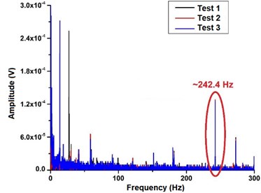
a)
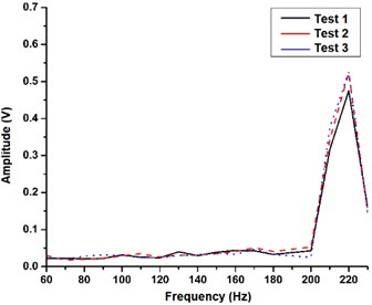
b)
3. Conclusions
By using a fiber optic with the FBG as a spring, enhances the cantilever natural frequency and strain uniformly strain the Bragg grating to increase the sensitivity to the vertical vibrations. The device has a linear response to the vertical vibrations applied (under the device), and this allows to get signals up to 242.4 Hz.
References
-
Todd M. D., Johnson G. A., Althouse B. A., Vohra S. T. Flexural beam-based fiber Bragg grating accelerometers. IEEE Photonics Technology Letters, Vol. 10, Issue 11, 1998, p. 1605-1607.
-
Berkoff T. A., Kersey A. D. Experimental demonstration of a fiber Bragg grating accelerometers. IEEE Photonics Technology Letters, Vol. 8, Issue 12, 1996, p. 1677-1679.
-
Basumallick N., Chatterjee I., Biswas P., Dasgupta K., Bandyopadhyay S. Fiber Bragg grating accelerometer with enhanced sensitivity. Sensors and Actuators A: Physical, Vol. 173, Issue 1, 2012, p. 108-115.
-
Casas Ramos M.-A., Sandoval Romero G.-E. Modified optical fiber Bragg grating accelerometer. Argentine School of Micro-Nanoelectronics, Technology and Applications, 2015.
-
Gere J. M., Goodno B. J. Mecánica De Materiales. Fourth Edition, Ceangage Learning, CDMX, Mexico, 2009.
-
Antunes P., Lima H., et al. Elastic constant measurement for standard and photosensitive single mode optical fibres. Microwave and Optical Technology Letters, Vol. 50, Issue 9, 2008, p. 2467-2469.
-
Antunes P., Lima H., et al. Optical Sensors Based on Fiber Bragg Gratings for Structural Health Monitoring. New Developments in Sensing Technology for Structural Health Monitoring. First Edition, Springer, 2011, p. 253-295.
Cited by
About this article

This work was supported by DGAPA-UNAM through financing of project PAPIIT IT101019. The authors are grateful to CONACYT for the financial support in the form of a scholarship for the Master’s and Ph.D. Engineering Program through the Universidad Nacional Autónoma de México.
