Abstract
This article focuses on the analysis of the properties of the car strut used to capture the engine torque reaction generated during fast acceleration. There is described the methodology of measuring the parameters needed to assess the force effect and also a simulation of the properties of a redesigned strut using the finite element method. The simulation confirmed the correctness of the design and also showed that very small asymmetry of cross section cause significant reducing of the load capacity of the strut and its easy damage.
1. Introduction
A mounting of the drive unit in the car is an important element not only for the comfort but also for safety. A properly designed strut ensures smooth transmission of the torque of the engine to the car body without shocks and also allows to the drive unit to move during the crash in the desired direction, it means outside the car's cab. The part that realizes the mounting is a strut. Its proper dimensioning and quality of production are crucial for the resulting vehicle behavior in different situations. The torque strut consists of a metal cast in which the silent blocks are located in the mounting eyes. During strut prototype testing were problems with permanent bending deformation or strut breaking. The aim of analyzes were to determine the real forces acting in the strut, to design a suitable strut geometry and to assess its properties by numerical simulation. Recent analysis has shown that the problem of bending is not only due to the magnitude of the force but also to the asymmetry of the cross section that leads to bending deformation when the tensile stress is applied. Therefore, a variant simulating the asymmetric cross-section was also analyzed.
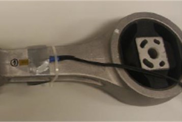
Fig. 1Sample of strut with tensiometers
2. Theory
When the impulse force acts on the body, it causes its deflection from the equilibrium position and then it freely vibrates at one or more own frequencies. A simple example is tapping on a glass (the undamaged glass generates another sound in comparison with broken glass). When applied to strut impact excitation is used. Methods based on the deconvolution of the measured response in the time domain are often used to obtain the force course. These methods can generally be used for problems that correspond with linear time invariant – LTI. For such a problem can be applied the principle of the superposition, which can be described by the equation in the form of Eq. (1):
where is the driving force or generally, input of the system, is the response of the structure or generally, output of the system and is the impulse response of the system to the Dirac unit pulse. Problems with impulse force are poorly conditioned, however, a number of theories dealing with improving of the conditionality have been compiled [1]. Jacquelin et al. dealt with the identification of the impact force on the aluminum plate, when they evaluated several methods for improving of the task conditionality (so-called regularization methods) and showed their parameter setting [2]. Jang et al. dealt with the general solvability of the inverse task for impact loads and performed numerical simulation for selected tasks using the Tikhonov and Landwerber-Fridmen regularization [3]. Furthermore, Kim and Lee have considered using the singular value decomposition to improve conditionality of the task and the method was verified experimentally on cantilever beam [4]. Wang and Xie proposed [5] a new method of regularization and performed its verification on the numerical model of the laminate cylinder with a slight improvement in results compared to the Tichon’s regularization [6].
3. Measurement
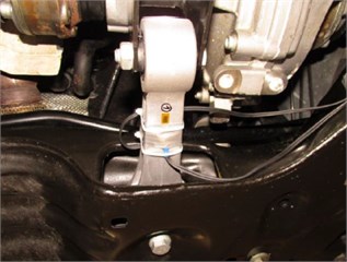
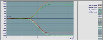
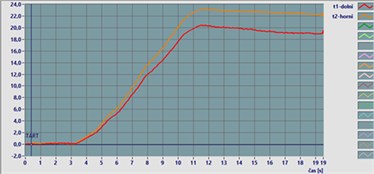
The force that acts in the strut during the launch was measured directly in the car. On the strut tensiometers on opposite side of a flange were glued. Then the tensiometers were verified and calibrated under known loading force. There tensile and bending loading was applied (Fig. 2). Then the strut was mounted to the car and the loading force was created by the fast releasing of a clutch under engine speeds up to a rev limiter. Totally five launches in first gear and reverse gear was carried out. The record of corresponding electrical voltage and forces are shown in Fig. 3. The maximum in first gear was 12,3, in reverse gear 18,8 kN. This curve was scaled for the obtaining of resulting force 45 kN – the force was multiplied by the constant 2,39, because higher loading capacity of new strut was expected. This adjusted curve was applied for ANSYS input in the form of data tab.
Fig. 2Calibration of tensiometers
a) Bending loading
b) Tensile loading
4. FE model
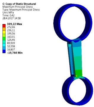
A new geometry of the strut was designed (Fig. 4). The design has respected a requirement of higher structural strength. Therefore, walls of the strut have a higher thickness; applied material is same as in previous type of the strut – aluminum alloy. Its mechanical parameters are shown in Table 1. Border conditions are seen also in Fig. 4. One side of the strut is fixed against a displacement and rotation in all directions by the help of cylindrical constrain. On opposite side a tensile force on cylindrical sector surface is applied. The direction of the force coincides with the symmetry axis of the strut. Initial conditions were following. The applied force that was measured in the car during extreme launch was assigned and applied in the form of input data tab in ANSYS. As a maximal stress criterion the tensile ultimate strength 310 MPa was taken. Under this stress the strut will be broken. Results of the simulation show a principal stress and deformation for symmetrical (Fig. 5) and asymmetrical strut (Fig. 6). As seen, in the case of symmetrical deformation tensile force leads to a symmetrical elongation of the strut beam. The force that causes achieving of material ultimate strength corresponds to 43,200 kN. Total elongation is 0,23 mm. Asymmetrical strut indicates ultimate strength at force about 18,9 kN. It means that relatively low change in symmetry caused by a different flange area about 10 %, reduces highest achieved force more than two times. The bending deformation on the end of the beam was 0,35 mm. It can be said that the accuracy of a mold used for the strut casting is very important and low differences in geometry of the strut causes extreme decreasing of applicable loading force.
Fig. 3Experimental data
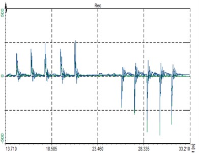
a) Time response of deformation [μm/m]
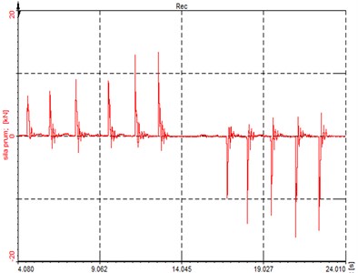
b) Time response of force [kN]
Fig. 4A new strut design; Border conditions. The cross-section of this design was enlarged, the main dimension of strut geometry – a pitch and total length were maintained


Fig. 5FE model of symmetrical strut
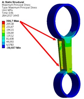
a) Maximum stress corresponding to ultimate strength
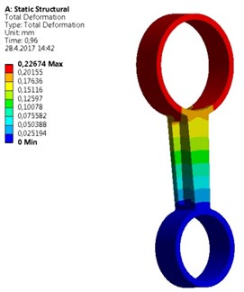
b) Total deformation of symmetrical strut
Fig. 6FE model of asymmetrical strut
a) Maximum stress corresponding to ultimate strength
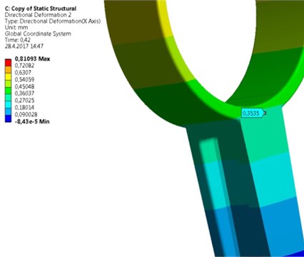
b) Bending deformation on the of the strut beam
Table 1Properties of applied material
Type | Young’s modulus [GPa] | Poisson’s ratio [GPa] | Bulk modulus [GPa] | Shear modulus [GPa] | Tensile yield strength [MPa] | Tensile ultimate strength [MPa] | |
Material | Aluminum alloy- | 71 | 0,33 | 69,6 | 26,69 | 280 | 310 |
5. Conclusions
The new geometry of the strut was designed. The design has been subjected to investigation using the finite element method. The strut with asymmetric cross section was also proposed, where the one flange of the I-beam had about 10 % smaller area compared to the second one. The problem with asymmetric cross section was discovered during the production. Loading force was obtained by measuring directly in the car. The simulation showed that the redesigned strut would transfer significantly higher force, more than twice compared with the force measured in the car. However, the strut with the asymmetric cross-section will break near to value measured in the car. Therefore, it is necessary to check the casting thoroughly to ensure that the problem does not appear again during production. It can be concluded that proposed strut is suitably dimensioned with a sufficient degree of safety.
References
-
Petrů M., Kovář R., Martinec T., Srb P., Lufinka Kulhavý A. P. Analysis and study of vibrations of a clamping device used for winding carbon fibers into the core of a frame. 53rd Conference on Experimental Stress Analysis, 2015, p. 287-292.
-
Jacquelin E., Bennani A., Hameli P. Force reconstruction: analysis and regularization of a deconvolution problem. Journal of Sound and Vibration, Vol. 265, Issue 1, 2003, p. 81-107.
-
Jang T. S., Baek H., Han S. L., Kinoshita T. Indirect measurement of the impulsive load to a nonlinear system from dynamic responses: inverse problem formulation. Mechanical Systems and Signal Processing, Vol. 24, Issue 6, 2010, p. 1665-1681.
-
Kim S. J., Lee S. K. Experimental identification for inverse problem of a mechanical system with a non-minimum phase based on singular value decomposition. Journal of Mechanical Science and Technology, Vol. 22, Issue 8, 2008, p. 1504-1509.
-
Choi I. H., Lim C. H. Low-velocity impact analysis of composite laminates using linearized contact law. Composite Structures, Vol. 66, Issues 1-4, 2004, p. 125-132.
-
Wang L., Xie Y. A novel regularization method and application to load identification of composite laminated cylindrical shell. Journal of Applied Analysis and Computation, Vol. 5, Issue 4, 2015, p. 570-580.
About this article

The activities of this Project LO1201 were financed with co-funding from the Ministry of Education, Youth and Sports (Czech Republic) as part of targeted support from the “National Sustainability Program I” programme.
