Abstract
The complex mechanical system which is a subsystem of mechatronic system composed with many continuous mechanical elements having the same length and variable cross section, loaded by the harmonic force is analyzed. The main subject of deliberation was to determine the flexibility of the mechanical subsystem with constant cross section using algorithms of exact and approximate methods. Next, the comparison of methods and the correction of the approximate method has been made. The model of subsystem of complex transverse vibrating mechanical system of freight wagon was considered and after deliberation the approximate method has been chosen. The presented research of subsystems establishes the foundation to complex systems analysis with cascade structure. By analyzing the diagrams of characteristics of confirmed system it has been determined that in case of approximate method the resonance frequencies cover with those which have been determined with the exact method. However, the values of the characteristic in other areas are different. Therefore, there is the mistake within the approximate method, which while of studying the single system does not have any influence because in resonance areas the characteristic values of the system approach to the infinity. However, the difference between values of flexibility within two methods has the great influence on the result of complex systems. That is why it was necessary to correct the results of the approximate method.
1. Introduction
The problems concerned with mechatronic systems and problems of electrostriction and piezoelectricity were presented for example in [8-10]. Other, diverse problems have been modelled by different methods [1, 2] and next they were examined and analyzed in (e.g. [3-7]).
2. The algorithm of the exact method for obtaining the solution of transverse vibrating free beam – simple subsystem of complex beam system
In the global case the equation of motion of the beam is considered:
where: is deflection at the time moment of the lining beam section within the distance x from the beginning of the system, – Young modulus, – mass density of material of the beam, – polar inertia moment of the beam cross section, – area of the beam cross section.
The boundary conditions of beam system are known as: free (), clamped (), pinned () and sliding () ends.
The solution of Eq. (1) is the function in form of:
After transformations own functions are obtained as:
The problem of determining of own function was presented for discrete-continuous transverse vibrating mechatronic systems in (e.g. [8-10]).
3. The algorithm of the exact method for obtaining the dynamical flexibility of transverse vibrating beam – subsystem of freight wagons
Taking into consideration that mechanical subsystem of transverse vibrating complex system is extorted with harmonic force in form , so one boundary condition in combination , , , Eq. (1) takes form:
After substituting of derivatives and transformation the deflection of the beam is considered as:
According to definition of dynamic flexibility it takes form:
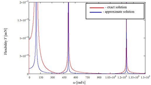
The graphs of absolute value of dynamical flexibility Eq. (6), obtained for , for combinations of boundary conditions: free end – () and pinned end – () are presented in Fig. 1 and for clamped end – () and sliding end – () – in Fig. 2.
Detailed transformations and final sentences of combinations of boundary conditions have been presented in (E.g. [8-10]).
4. The algorithm of approximate method for obtaining the dynamical flexibility of transverse vibrating beam - subsystem of freight wagons
It has to be considered that if the beam is under the action of moment with continuous factorization threw the beam length with the value on the length unit – then the equation of motion of the element with length lining in the point is:
where: .
Using approximate method – Galerkin’s one, the solution of Eq. (7), after transformations is given in the form:
After transformation, the equation of dynamical flexibility is:
In general case the dynamical flexibility at the arbitrary point of the beam after transformations gets a form of:
Plots of absolute values of dynamical flexibility defined by Eq. (10) for combinations of boundary conditions ()-() and ()-() are presented in Fig. 1 and 2.
Fig. 1Absolute values of dynamical flexibility of the beam with combination of boundary conditions (F) and (P), for n= 1, 2, 3
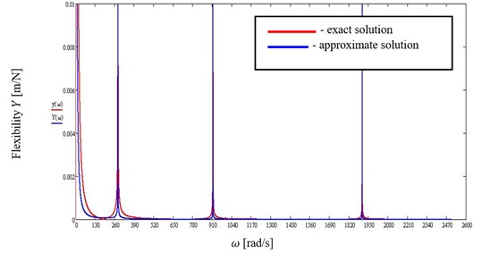
Fig. 2Absolute values of dynamical flexibility of the beam with combination of boundary conditions (C) and (S), for n= 1, 2, 3
5. Conclusion
The problems presented in this paper are considered to be the base and introduction to the solution of inverse task, meaning the synthesis of transverse vibrating complex mechanical or mechatronic beam systems with assumed frequency spectrum.
References
-
Bellert S., Woźniacki H. The Analysis and Synthesis of Electrical Systems by Means of the Method of Structural Numbers. WNT, Warszawa, 1968, (in Polish).
-
Berge C. Graphs and Hypergraphs. American Elsevier Publishing Co., Inc., New York/North Holland Publishing Co., Amsterdam-London, 1973.
-
Buchacz A. Modelling, synthesis and analysis of bar systems characterized by a cascade structure represented by graphs. Mechanism and Machine Theory, Vol. 30, Issue 7, 1995, p. 969-986.
-
Białas K., Buchacz A., Dzitkowski T. Synthesis of Active Mechanical Systems with Dumping in View of Polar Graphs and Structural Numbers. Monograph No. 230. Silesian University of Technology Press, Gliwice, 2009, (in Polish).
-
Buchacz A., Żurek K. Reverse Task of Dynamic of Active Mechanical Systems by Means the Graphs and Structural Numbers Methods. Monograph No 81. Silesian University of Technology Press, Gliwice, 2005, (in Polish).
-
Buchacz A. Exact and approximate analysis of mechanical and mechatronic systems. Journal of Achievements in Materials and Manufacturing Engineering, Vol. 33, Issue 1, 2009, p. 47-52.
-
Buchacz A. Modelling, synthesis, modification, sensitivity and analysis of mechanic and mechatronic systems. Journal of Achievements in Materials and Manufacturing Engineering, International OCOSCO World Press, Vol. 24, Issue 1, 2007, p. 198-207.
-
Buchacz A. The supply of formal notions to synthesis of the vibrating discrete-continuous mechatronic systems. Journal of Achievements in Materials and Manufacturing Engineering, International OCOSCO World Press, Vol. 44, Issue 2, 2011, p. 168-178.
-
Callahan H. B. Vibration monitoring of cylindrical shells using piezoelectric sensors. Finite Elements in Analysis and Design, Vol. 23, 1996, p. 303-318.
-
Kurnik W. Damping of mechanical vibrations utilizing shunted piezoelements. Machine Dynamics Problems, Vol. 28, Issue 4, 2004, p. 15-26.
About this article

This work has been conducted as a part of Research Project PBS2/A6/17/2013 supported by the National Centre for Research and Development in 2013-2016.
