Abstract
The main objective of presented article is finding the relationship between the change in the intensity of the volumetric flow and values of vibration parameters (indirect measurements – vibration sensors mounted on the pump body). The study was subjected to the multi-piston pump (type PV Plus made by the Parker Hannifin) equipped with built-in volumetric performance controller.
1. Introduction
Multi-piston pumps are a commonly used source of the hydraulic fluid stream in the average and high power hydrostatic drives. They are characterized by high efficiency, ability to work with high pumping pressure [1] and minimal discharge flow pulsation [2, 3]. The main advantage of the hydrostatic drive is the ability to achieve high power flux-density.
A noticeable tendency in hydrostatic [4] systems is revealed in the form of minimization of the mass, overall dimensions and at the same time increasing a power density delivered by pumps. An important task is finding the optimum between a power and a mass. A solution of described problem is easy at the construction stage of new pumps. For pumps used in industrial applications changing structural parameters are not possible. In such case remains only control of productivity factors. The increase in power causes an amplification of vibration, resulting in excessive noise and reduced service life of components [5].
The article presents the preliminary results of the studies of pressure pulsation and vibration of the multi-piston axial swash-plate hydraulic pump, type PV032R1K1T1NMTP manufactured by Parker Hannifin. It is a variable displacement pump operating within the LS (Load Sensing) system.
2. Description of the measuring station
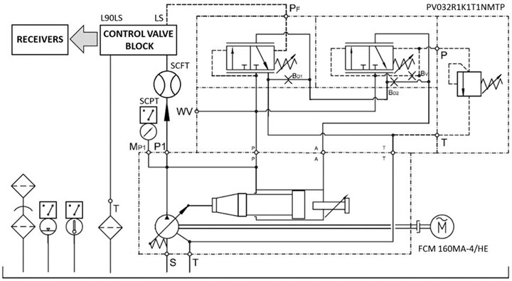
Fig. 1 presents the simplified diagram of the test stand. The hydraulic system comprised of:
– A multi-piston, variable displacement axial pump [6, 7], type PV032R1K1T1NMTP (displacement volume/rotation: 32 cm3, pressure controller),
– Three-phase asynchronous motor, type FCM 160MA-4/HE manufactured by AC-Motoren, driving the tested pump,
– L90LS distributor manufactured by Parker Hannifin with four proportional sections,
– Hydraulic receivers (three single rod-end cylinders and rotational hydraulic motor).
The measurements were taken using:
– Diagnostic tool Service Master Plus with the SCPT-160-C2-05 pressure sensor and the SCFT-060-C2-05 flow meter,
– A set for vibroacoustic tests featuring a IFM VSE100 data acquisition and processing module and IFM VSA005 accelerometers.
Fig. 1Simplified diagram of the test stand
Measurements of the hydraulic quantities were done with 1 ms sampling and no filtration, and the signals from accelerometers were sampled with the resolution of 1.52 Hz and filtered using the low pass filter with the frequency of 1950 Hz. The filtered acceleration signals were then subject to the FFT analysis FFT.
Pump tests were carried out for three different pressure settings: 16 bar (stand-by pressure, resulting from the settings for the operation within the LS system), 60 bar and 120 bar.
For the pressure of 60 bar and 120 bar we forced the pump performance settings to be circa 23 dm3/min and 43 dm3/min (similar to 50 % and 100 % of the nominal efficiency). The pressure of 16 bar corresponded with the pump working with minimum efficiency, necessary to repair leakage and maintain stand-by pressure with LS control.
Due to the limit of power caused by the motor driving the tested pump, the tests were not carried out with higher pressure, close to the nominal 350 bar.
3. Pressure pulsation analysis
The tested pump is a nine-piston one, so the theoretical discharge flow pulsation [8] is lower than 1.6 %. The discharge flow pulsation and flow resistance on the discharge side of the pump are the cause of the pumping pressure pulsation. Assuming that the hydraulic resistance and turbulent flow of the incompressible liquid were constant, the pressure pulsation would amount to little over 3 %.
Fig. 2(a) presents the registered spectrum of the pumping pressure frequency. It is easy to observe its periodicity connected with the process of cylinders entering the pumping section. It is also possible to notice modulation of the fundamental frequency of pressure pulsation that may be a result of the asymmetry of the pump design or irregular leaks in the particular cylinders of the pump.
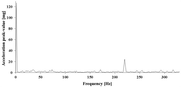
The assumption that this might be the effect of the leaks is proven by the fact that the mentioned modulation of the fundamental pressure pulsation is especially visible for higher pumping pressure (Fig. 2(b)).
The results of the tests are presented in Table 1. Apart from the pumping pressure and its pulsation, also its frequency was determined.
As can be seen, in all cases the pressure pulsation did not exceed the theoretical expectations. It may be the effect of the compressibility of the hydraulic liquid. The pulsation frequency determined from the time signals are very close to the predicted frequency of circa 218 Hz, resulting from the rotational speed of the pump shaft (about 1450 rpm). In three cases (two of which are stand-by pump operation with maintained pressure) significantly lower frequency of the pressure pulsation was observed, as shown in Fig. 3.
Fig. 2Pressure pulsation with the maximum discharge of the pump and pumping pressure equals: a) 60 [bar], b) 120 [bar]
![Pressure pulsation with the maximum discharge of the pump and pumping pressure equals: a) 60 [bar], b) 120 [bar]](https://static-01.extrica.com/articles/15392/15392-img2.jpg)
a)
![Pressure pulsation with the maximum discharge of the pump and pumping pressure equals: a) 60 [bar], b) 120 [bar]](https://static-01.extrica.com/articles/15392/15392-img3.jpg)
b)
Fig. 3Pressure pulsation with zero discharge of the pump and pumping pressure of 120 bar
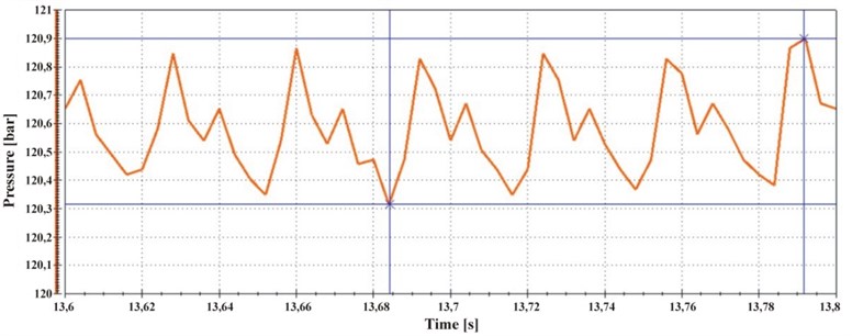
Such a course of the pressure pulsation may be caused by the inconsistent discharge from the particular pump cylinders. For instance, leakage from one of the cylinders might be greater than from the other ones. However, the clarifying interpretation of the obtained results will require further research.
Table 1Characteristic parameters of tested pump
Measure No. | Flow rate setting [%] | Pressure setting | [bar] | [bar] | [bar] | [Hz] | Pressure pulsation [%] |
1 | 0 | stand-by | 15.78 | 15.89 | 15.66 | 214.8 | 1.46 |
2 | 50 | low | 60.62 | 60.95 | 60.3 | 31.9 | 1.07 |
3 | 100 | low | 58.37 | 58.81 | 57.88 | 214.3 | 1.59 |
4 | 0 | low | 59.8 | 59.91 | 59.65 | 34.46 | 0.43 |
5 | 0 | high | 120.6 | 121 | 120.3 | 32.81 | 0.58 |
6 | 50 | high | 121.2 | 121.6 | 120.8 | 209.2 | 0.66 |
7 | 100 | high | 120.6 | 121.1 | 120.1 | 211.8 | 0.83 |
4. Pump vibration analysis
Two accelerometers were positioned on the body of the pump, one in axial and one in radial direction. The acceleration signals were subject to the FFT online analysis and then the received spectra of acceleration were registered. The obtained vibration spectra in the stand-by mode are shown in Figs. 4 and 5, vibration for the operation of the pump with the greatest load is shown in Figs. 6 and 7.
Fig. 4Spectrum of vibration acceleration in axial direction – pump operating in stand-by mode
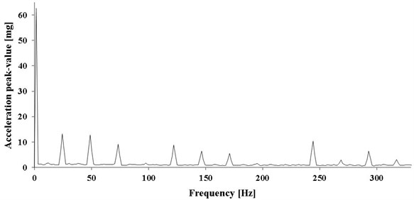
Fig. 5Spectrum of vibration acceleration in radial direction – pump operating in stand-by mode
The presented spectra indicate that the pump vibration is influenced by the frequency of the pump shaft rotation (Figs. 4, 6 and 7) and the frequency with which the cylinders enter the pumping section (Figs. 5, 6 and 7). Vibration induced by the cooperation with the electric motor and pump shaft rotation reveal not only the impact of the fundamental frequency, but also the harmonics (especially the first harmonic). For that reason, the table of results (Table 2) includes frequencies and amplitudes for:
– Frequency of pump shaft rotation (),
– The first harmonic of the pump shaft rotation (),
– Frequency with which the cylinders enter the pumping section ().
Fig. 6Spectrum of vibration acceleration in axial direction – pump operating with maximum discharge and pumping pressure of 120 bar
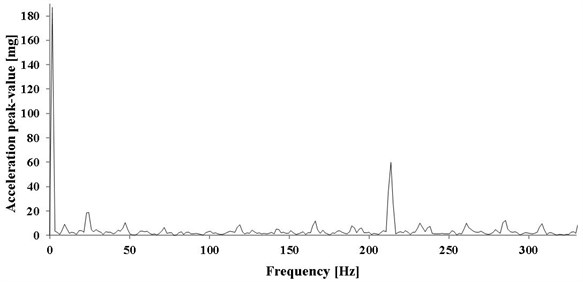
Fig. 7Spectrum of vibration acceleration in radial direction – pump operating with maximum discharge and pumping pressure of 120 bar

Table 2Vibration parameters
Measure No. | Vibration in axial direction | Vibration in radial direction | ||||||||||
[Hz] | [mm/s2] | [Hz] | [mm/s2] | [Hz] | [mm/s2] | [Hz] | [mm/s2] | [Hz] | [mm/s2] | [Hz] | [mm/s2] | |
1 | 24.4 | 130.2 | 48.8 | 126.4 | – | – | 24.4 | 35.0 | 48.8 | 36.3 | 219.7 | 175.1 |
2 | 24.4 | 165.4 | 48.8 | 132.1 | 222.8 | 50.6 | 24.4 | 75.5 | 48.8 | 55.0 | 218.2 | 386.1 |
3 | 24.4 | 156.2 | 48.8 | 185.4 | 216.7 | 893.7 | 24.4 | 63.5 | 48.8 | 268.3 | 216.7 | 525.3 |
4 | 24.4 | 170.2 | 48.8 | 115.5 | 219.7 | 447.1 | – | – | 48.8 | 80.6 | 219.7 | 654.7 |
5 | 24.4 | 57.8 | 48.8 | 33.6 | 219.7 | 260.7 | 22.9 | 98.0 | – | – | 219.7 | 258.4 |
6 | 24.4 | 198.3 | 48.8 | 54.2 | 216.7 | 333.4 | 22.9 | 139.0 | 47.3 | 68.8 | 216.7 | 372.2 |
7 | 24.4 | 175.2 | 47.3 | 105.7 | 213.6 | 551.0 | 24.4 | 96.7 | 47.3 | 287.3 | 213.6 | 297.1 |
In case of vibration in axial direction we may notice the correlation between the amplitude of vibration and the pump load for frequencies close to the frequency of pressure pulsation. On the other hand, vibration of the pump shaft rotation frequency and the first harmonic present values similar to different modes of pump operation. It can be assumed that they are the effect of the pump or pump-asynchronous motor operation.
In case of the radial vibration, the correlation between the pump load and vibration amplitude is particularly noticeable not only for the frequency similar to the pressure pulsation frequency. It can be observed that with the increase of pump load, the amplitude of radial vibration of the double pump shaft rotation frequency also increases.
Seemingly, we might assume that the pump vibration of 220 Hz frequency is the result of the pumping pressure pulsation. This is, however, not the case. In fact, both pressure pulsation and pump vibration are the result of the same thing: subsequent cylinders engaging in the pumping process. This basically results in discharge flow pulsation and then pressure pulsation as well as pulsation of force coming from the cylinder – piston assembly at the moment of entering the pumping section.
5. Conclusions
The spectra of pumping pressure and vibration acceleration on the body, obtained as a result of the experimental tests of the multi-piston axial PV pump (by Parker Hannifin), demonstrate some correlation. In case of both pumping pressure and spectra of vibration in axial and radial direction we may observe the impact of the cylinders engaging in the pumping process [9]. For that reason it is not advised to search for casual connection between the pressure pulsations and pump vibration; both phenomena are the effects of the third cause [10], as mentioned above.
Throughout the study, it has been observed that some of the recorded spectra of pumping pressure do not reflect the discharge flow pulsation, resulting from the periodicity of the process of the subsequent cylinders entering the pumping section. Such spectra may result from the inconsistency of discharge from particular cylinders and the impact of the discharge side of the pump (that can be treated and the low pass filter). Another reason might be the periodically changing leakage between the cylinder barrel and the valve plate. The clarifying explanation of this phenomenon would be possible only after some further modeling and experimental research.
References
-
Łataś W., Stojek J. Dynamic model of multi-piston swash-plate hydraulic pump. Mechanics. Technical Transactions, Vol. 108, Issue 2, 2011, p. 113-126, (in Polish).
-
Ickiewicz J. Hydraulic and mechanical vibrations of gear pump. Hydraulic and Pneumatics, Issue 3, 2013, p. 12-16, (in Polish).
-
Kudźma Z. Damping of pressure pulsations and noise level in hydraulic systems in transient and established conditions. Wroclaw University of Technology Publishing, Wroclaw, 2012, (in Polish).
-
Milecki A. Linear electrohydraulic servo drives. Poznan University of Technology Publishing, Poznan, 2003, (in Polish).
-
Tomasiak E., Klarecki K., Barbachowski E. Servo drives in machine construction. Hydraulics and Pneumatics, Issue 1, 2009, p. 16-20, (in Polish).
-
Materials developed by Parker Hannifin. Direct Operated Proportional DC Valve Series D1FB, http://www.parker.com/.
-
The hydraulic trainer. Proportional and servo valve technology. Mannesmann Rexroth AG, Vol. 2, Lohr a. Main, 1998, (in German).
-
Barbachowski E., Klarecki K. Methods for correcting the characteristics of proportional valves. Selected Engineering Problems, Vol. 2, 2011, p. 29-34, (in Polish).
-
Jakubowski D., Gniłka J., Wszołek G., Czop P. Optimization of a hydraulic damper performance with the use of fluid-structure simulation. Advanced Materials Research, Vols. 452-453, 2012, p. 1356-1360.
-
Kost G., Nierychlok A. Presentation of the concept of stability of the hybrid powertrain by the Lyapunov theory. Journal of Vibroengineering, Vol. 14, Issue 1, 2012, p. 183-188.
About this article
