Abstract
A vibration-based diagnostics method of large-power 1JAH5 (Siemens) DC motors over 660 kW used in paper machines is proposed in the article. When studying vibration spectrograms it was found that 8 Hz frequency shock loads considerably prevail over vibration, which corresponds to this motor rotor speed. The cause of vibration initiation generated by the motor rotor spinning was determined by theoretical methods. Vibration on the one hand appears as a result of bearings wear accompanied by bearing cage deformation and their shaft spinning axes reciprocal displacement, and on the other hand, by shaft eccentricity radii enhancement which causes dynamic loads increase affecting bearing units. The authors of the paper have come to the conclusion that in order to lower vibration of the motor it is necessary to replace the bearings with the new ones, the former due to a long-term service (over 30 years), vibration and shock load effects having exhausted their life span.
Highlights
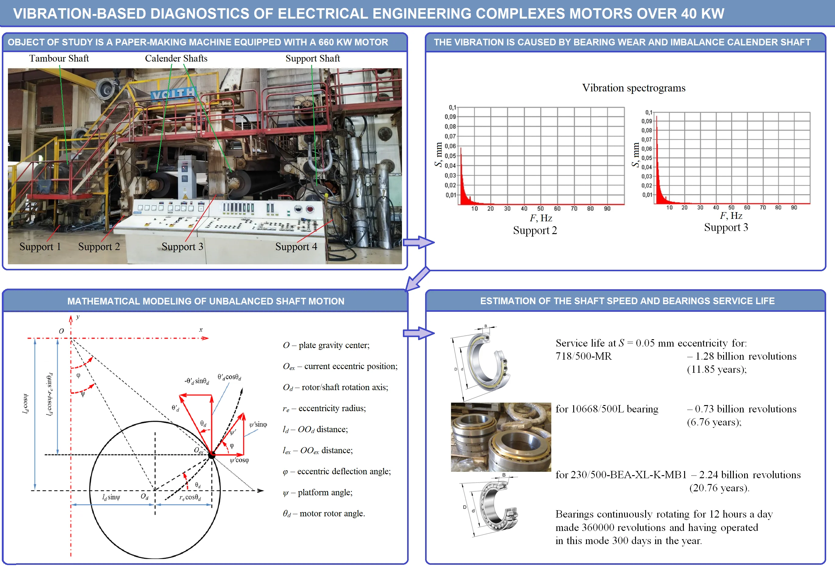
- A new method of vibration-based diagnostics of high power multi-motor (multi-shaft) machines is disclosed on the example of a paper-making machine with a 660 kW DC motor.
- Vibration diagnostics of the machine supports made it possible to preliminarily establish the cause of the intense vibration.
- Mathematical modeling of the shaft motion made it possible to confirm that worn bearings of an unbalanced calender shaft are the cause of vibration.
- The bearing life assessment showed that their service life expired about 20 years ago.
1. Introduction
The main reason for motor base vibration is violent vibrations of rotor with worn-out bearings [1-5]. In this paper the reason for electromechanical complex (EMC) increased vibration is theorized by the authors aiming at its further improvement and service life increase.
Bearings vibration with rotation frequency can appear for one of three reasons: bearing ring slipping on the mounting seat, outer ring rolling off or inner ring wearing [1-6]. The last two reasons are accompanied by the bearing geometry change and therefore by shaft eccentricity initiation. There are two types of eccentricity: static one, which is characterized by radial or angular rotor spinning axis displacement about stator axis; and a dynamic one, characterized by varying with time rotor spinning axis position about stator axis [7-10]. It becomes evident that dynamic shaft eccentricity is the most dangerous one, because as it rotates, inertia force appears having additional force impact on constructional elements as well as swinging the construction itself. The force which appears when unbalanced shaft with dynamic eccentricity rotates changes directionally with the period corresponding to the shaft full turn and is proportional to its squared rpm [7]. Static eccentricity does not have any significant impact on the machine operation.
2. Vibration tests
When carrying out vibration tests of large-power DC motor comprised in EMC, the following spots were selected: 4 on each support (Fig. 1). Vibration was measured within 2-100 Hz frequency range (for greater measurement precision – within low frequency range) vertically, while the accelerometer was mounted on supports. Vibration signals diagrams picked by the vibration meter on the set spots were transferred to the computer, and spectrograms of the recorded signals were obtained, some of them shown in Fig. 2.
Fig. 1Vibration-based diagnostics of EMC (paper machine)
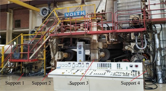
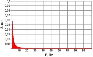
Fig. 2Vibration spectrograms
a) Support #2
b) Support #3
Processing vibration tests results brings about the following preliminary conclusions:
1. Amplitude of spectrum fundamental harmonics (2 Hz) does not increase 0.1 mm being 0.05-0.1 mm on floor near its support and 0.025 mm on the support;
2. Shock loads largely (10-100 times) prevail over vibration;
3. 7-8 Hz harmonics is observed nearly in all spectra corresponding to the electric motor rotor frequency.
The reason for vibration is supposed to be the electric machine rotor bearings wear, as the crack in EMC base initiated after relatively long (over 30 years) machine operation.
3. Physical model of rotor spinning in a large-power motor
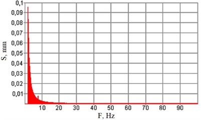
Let us consider a physical model of rotor spinning in a large-power motor, having a certain eccentricity. As a rule, eccentricity parameter is expressed by ∙, where – rotary mass, and – the distance between the rotor shaft and its spinning axis [11-12]. Assume that shaft eccentricity is caused by eccentricity (load) of mass placed at distance from rotor spinning axis (Fig. 3).
Motor with an unbalanced rotor is fixed on the platform by mounts (supports) described by visco-elastic bindings [13-14]. Thus, when the rotor is spinning, the motor is able to oscillate normally about the plate plane surface. When the motor is running, the platform itself swings affected by inertia forces of the motor.
Fig. 3Eccentric complex motion decomposition along linear speed vectors in xy coordinate system
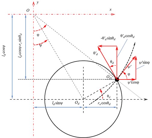
Eccentric complex motion is decomposed along axis and as visually explained in Fig. 3. The distance from plate gravity center to current eccentric position ( arm of length) and eccentric deflection angle function from the vertical symmetry axis when swinging are determined by:
where – platform angle, – motor rotor angle, – distance from the rotor spinning axis to the eccentric mass center, – distance between the plate gravity center to the rotor spinning axis ( arm).
Arm length and deflection angle are variables depending on rocking angle and motor rotor angle . Derivatives of these values in time are expressed:
Taking into consideration Eq. (1) and Eq. (2) the expression of the kinetic energy for the system’s moving masses (Fig. 3) can take on the following [12]:
where and – motor displacements about horizontal and vertical axes respectively, – swinging plate inertia moment, spinning rotor inertia moment .
Potential energy is determined by compression and extension of the motor rotor supports, thus its expression is the following:
where and – rotor supports resulting elastic coefficients horizontally and vertically, – resulting support elastic coefficient, preventing this rotor from swinging.
The system is also affected by other forces, for example, damping in mounting units [12]:
Electromagnetic torque effect and load torque on asynchronous motor shaft [11, 14]:
where , , – resulting mount damping coefficients in , and directions. At a first approximation, counterforces of mount bodies’ reciprocal displacements are supposed to depend on speed while the energy released is proportional to the value of these displacements. Damping effect is also observed at electromechanical energy conversion in asynchronous motor. The point is that electromagnetic torque is formed as a result of stator and rotor winding current interaction. In resistances of these circuits, losses appear at the current flow causing energy dissipation effect [15].
According to Lagrange principle, for each independent coordinate or state variable, considering Eq. (5) and Eq. (6), the following dynamic equilibrium equations are valid:
Using Eq. (3), Eq. (4) and Eq. (7), the kinematic and energy processes are described in a system with a DC motor, which rotates a calender shaft weighing 29.5 tons at a maximum permissible speed of 1320 rpm. Basing on recalculated motor shaft displacement values, bearings’ life was determined which are used (or suitable for use) on the paper machine in question according to Eq. (8) (disregarding load axial component) [16]:
where – durability in millions of rpm, – dynamic load rating, – dynamic load, 3 for ball-bearings, – load coefficient, – radial load, – coefficient of rotation, – safety coefficient, – temperature coefficient.
Radial load in its turn represents shaft vibration action and can be determined as follows [16]:
where – vibration displacement root-mean-square value, – vibration fundamental harmonics frequency, – shaft mass.
Thus, for 718/500-MR bearing at 0.05 mm eccentricity, estimated life is 1.28 billion revolutions, for 10668/500L bearing – 0.73 billion revolutions and for 230/500-BEA-XL-K-MB1 bearings – 2241.54 billion revolutions (whereas these bearings’ nominal rpm is less than the calender roll speed (500 rpm)). Therefore, bearings continuously rotating for 12 hours a day made 360000 revolutions and having operated in this mode exhausted their life span in 10 years.
4. Conclusions
The main reason for EMC vibration was found to be an increase in DC motor rotor unbalance, driving the machine calender rolls. Maximum vibration at the motor rotor speed was observed in this area. Eccentricity increase aggravated by shock loads contributed to destruction of bearings on which the electric machine rotors are mounted.
Mathematical models were proposed aimed at dynamic mechanical processes estimation in oscillatory system with unbalanced shafts, their rotation causing both forward and rotational motions of its elements.
References
-
K. G., V. B., and R. G., “Vibration diagnosis of turbomachinery coupled with induction motor,” Vibroengineering Procedia, Vol. 35, pp. 1–6, Nov. 2020, https://doi.org/10.21595/vp.2020.21768
-
Z. Yang, “Automatic condition monitoring of industrial rolling-element bearings using motor’s vibration and current analysis,” Shock and Vibration, Vol. 2015, pp. 1–12, 2015, https://doi.org/10.1155/2015/486159
-
N. Barkova, A. Barkov, and D. Grishchenko, “Vibration diagnostics of equipment units with gas turbine engines,” Vibroengineering Procedia, Vol. 25, pp. 89–94, Jun. 2019, https://doi.org/10.21595/vp.2019.20723
-
A. Barkov, N. Barkova, and J. Mitchell, “Condition assessment and life prediction of rolling element bearing,” Sound and Vibration, Vol. 6, pp. 10–17, 1995.
-
R. B. Randall, Vibration-Based Condition Monitoring. Chichester: John Wiley and Sons, 2011.
-
S. G. Kaminsky, “Development of methods for vibration-based diagnostics and restoration of electric drive oilfield pumping units,” (in Russian), Ph.D. Thesis, Ufa, 2004.
-
Y. N. Vaskovsky and A. A. Geraskin, “Vibration diagnostics of the rotor eccentricity of induction machines based on the analysis of vibration disturbance forces,” (in Russian), Bulletin of NTU "KPI": Electric Machines and Electromechanical Reconstruction of Energy, Vol. 38, pp. 52–62, 2014.
-
V. P. Shuisky, Calculation of Electrical Machines. (in Russian), Leningrad: Energy, 1968.
-
S. Nandi, S. Ahmed, and H. Toliyat, “Detection of rotor slot and other eccentricity-related harmonics in a three-phase induction motor with different rotor cages,” IEEE Power Engineering Review, Vol. 21, No. 9, pp. 62–62, Sep. 2001, https://doi.org/10.1109/mper.2001.4311622
-
S. Keller, M. T. Xuan, J.-J. Simond, and A. Schwery, “Large low-speed hydro-generators – unbalanced magnetic pulls and additional damper losses in eccentricity conditions,” IET Electric Power Applications, Vol. 1, No. 5, pp. 657–664, 2007, https://doi.org/10.1049/iet-epa:20060504
-
A. I. Baikov et al., “Analysis of motors vibrations mounted on single base,” (in Russian), in Proceedings of the 9th International Conference on Automated Electric Drive, pp. 8–12, 2016.
-
B. A. Gordeev, A. I. Baikov, and A. B. Darienkov, “Modeling of the vibration mount test processes at the experimental stand,” (in Russian), Mechanical Engineering: Network Electronic Scientific Journal, Vol. 5, No. 2, pp. 56–61, 2017.
-
A. Ermolaev et al., “Analysis of mechanical power flow in an electric drive operating under vibration conditions,” in 10th Int. Conf. on Electrical Power Drive Systems (ICEPDS), pp. 275–279, 2018.
-
A. Ermolaev, A. Plekhov, and D. Titov, “The study of electric drive mutual influence in the multi-motor machines,” in 2020 11th International Conference on Electrical Power Drive Systems (ICEPDS), pp. 1–5, Oct. 2020, https://doi.org/10.1109/icepds47235.2020.9249361
-
I. A. Selivanov and Omelchenko E. Y., “Electromechanical properties in an induction motors,” (in Russian), Bulletin of MSTU n.a. G.I. Nosov, Vol. 3, pp. 35–38, 2011.
-
“Gost 18855-2013 (Iso 281: 2007) Rolling Bearings. Dynamic Load Ratings; Rated Life (Adj.),” (in Russian), Interstate Standard, 2015-07-01, 2015.
About this article

The research was supported by Russian Science Foundation (Project No. 20-19-00372).
