Abstract
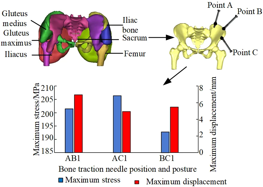
Robot-assisted reduction of pelvic fracture, the bone traction needles need to be inserted into the iliac bone of the affected pelvis, and the clamping instrument of the robot is connected to the bone traction needle. The biomechanical characteristics of the pelvic musculoskeletal tissues are different with the different spatial position and orientation of the bone traction needle. In this paper, a new PA-MTM model considering the pinnate angle of skeletal muscle is proposed to analyze the muscle force of skeletal muscle. According to the planned reduction path, reduction force during the reduction process is calculated. Based on the pelvic CT scan data and the muscle distribution of the pelvis, the musculoskeletal model of the fractured pelvis is reconstructed. Then, the finite element model of the pelvic musculoskeletal tissue with bone traction needle is established. The maximum reduction force is applied on the bone traction needles, and the stress distribution of the pelvic musculoskeletal tissue with the needles in different spatial position and orientation is comparatively studied. The results show that the suitable force point on bone traction needle is S1 point. When the bone traction needle is inserted into the iliac crest and the anterior inferior iliac spine, the pelvis is in a good stress state.
Highlights
- A new PA-MTM model of skeletal muscle is proposed
- The suitable force point on bone traction needle is determined
- The suitable spatial position and orientation of the bone traction needles are determined
1. Introduction
The pelvis which is a pelvis skeleton connecting the spine and lower limbs is formed by the posterior sacrum, coccyx and left and right hip bones. The pelvis not only transfers body weight to the lower limbs, and serves as the basis for the movement of the free lower limbs, but also supports the protection of intra-abdominal organs. Pelvic fracture is one of the most complex and serious fractures in trauma orthopedics, and known as the “crown field” of trauma orthopedics, accounting for about 3 %-8 % of all fractures in the body, especially the increasing incidence of combined injuries and multiple injuries in the body accompanied by pelvic and acetabular fractures, which can account for 25 % in patients with multiple injuries [1].
The key to pelvic fractures treatment is to obtain a good reduction and restore the stability of the pelvic ring and stable hemodynamics [2]. For stable pelvic fractures, most doctors mainly adopt conservative treatment, including reduction through suspension traction, femoral supracondylar traction and lateral lying [3]. For unstable pelvic fractures, commonly methods of pelvic fracture reduction include external fixator therapy [4-7], open reduction and internal fixation [8], and percutaneous minimally invasive screw internal fixation [9]. With the development of medical robot technology, pelvic fracture reduction robot began to be applied in pelvic fracture reduction surgery [10-12].
The biomechanical analysis of pelvic musculoskeletal tissue is the basis of robot-assisted pelvic fracture surgery. In the aspect of biomechanical finite element analysis of pelvic musculoskeletal tissue, some scholars have carried out some researches. In 2007, Phillips et al. [13] conducted a finite element analysis in which the pelvis is supported by muscular and ligamentous boundary conditions, and the analysis is compared to an analysis in which the pelvis is restrained by fixed boundary conditions applied at the sacroiliac joint. The results showed that the inclusion of muscular and ligamentous boundary conditions is found to lower the occurrence of stress concentration within the cortex. And it can also be used to study the role of muscles in a range of activities. In 2014, Wang Chengyou from Harbin University of Science and Technology [14] reverse-accurately established the human hip bone, muscle, fat, skin and other tissue models according to the anatomical structure of the human hip tissue. Based on the 3D reconstruction results of the hip tissue, the biomechanical model of the skeletal, muscle-tendon system of the human hip was established by finite element method. In ANSYS, the femur and muscle were analyzed by pressure and tension respectively, and the results showed that the biomechanical model of the muscle and bone could accurately reflect the biomechanical characteristics of the bone and muscle. In 2019, Wang Monan et al. [15] from Harbin Polytechnic University, based on the concept of muscle groups, finite element models of hip and leg were established, which were simulated of distal femur and central two load modes. Then, the simulation results were compared with lower limb dynamic three-point experiment, and the model was verified that can carefully reflect human anatomy structure of lower limbs. Moreover, the muscle model can replace living body or corpse for biomechanical experiment research.
About the muscle force and reduction force during the pelvic fracture reduction process, some scholars have carried out related studies. In 2009, Esmat Elabjer et al. [16] measured the muscle and muscle fiber length, and calculated the muscle volume, physiological cross-sectional area, the muscle force and direction of the relevant muscles during the fracture of the iliac crest, pubis and ischium. The results showed that the gluteus medius muscle played the most important role in the iliac crest fracture. The erector muscles produce the strongest upward pull force, with the main anterior, medial, and downward pull forces produced by the iliopsoas muscles. The pelvic fracture CT data were used to calculate the muscle forces acting on the broken bone, in order to provide additional data for the optimal surgical plan to ensure stable fixation of the patient. In 2015, Ioannis Georgilas et al. [17] in Bristol Robotics Laboratory performed the reduction of proximal femoral and femoral neck fractures, in order to test the maximum fracture reduction force and reduction moment, which is conducive to create a safe, dynamic and stable minimally invasive robot-assisted fracture surgery system. In 2019, Wang Yu et al. [18] from Beihang University proposed the concept of elastic traction, and built an experimental platform for simulating reduction of pelvic fractures with simulated muscles. Reduction experiments were performed, in order to verify that the elastic traction method had the effect on pelvic fracture reduction force and operating flexibility.
For the pelvic fracture reduction, multiple bone traction needles are inserted into the bone block, then they are connected to the clamping mechanism. The spatial position and orientation of bone traction needles are closely related to the stability of pelvic clamping and the safety of the reduction operation. Many scholars have studied the influence of fixing screws after reduction on the stability of pelvic reduction and the biomechanics of musculoskeletal tissue.
However, the influence of different spatial position and orientation of two bone traction needles on the biomechanics of musculoskeletal tissue during the pelvic fractures reduction, has not been studied.
The biomechanics of circumpelvic musculoskeletal tissue with the bone traction needles are studied. Firstly, based on a new skeletal muscle model named PA-MTM (Pinnation Angle-Muscle Tendon Model), the muscle force of a pelvic fracture changing with the reduction path is calculated. Then, the pelvic fracture reduction force and moment is calculated according to the reduction path. The pelvic fracture musculoskeletal model is established by the reverse reconstruction technology. The reduction force is applied on the bone traction needles, and the finite element analysis of the pelvic musculoskeletal tissue with bone traction needles is performed. Finally, reasonable force point and position and orientation of the bone traction needle can be obtained.
2. Muscle force analysis of tile C type pelvic
According to Tile classification standard, pelvic fracture types can be divided into A, B and C. Type A is stable fracture, mainly including avulsion fracture of iliac crest, pelvic ring fracture of iliac wing separation or minor displacement, and transverse fracture of sacrum or coccyx. Type B is partially stable fracture, mainly including unilateral external pronation instability injury, internal pronation instability injury and bilateral partially stable fracture. Type C is an unstable fracture, mainly iliac fracture, sacroiliac joint dislocation, and sacrum fracture. In this paper, a biomechanical study of Tile C pelvic fracture is performed.
2.1. Skeletal muscle model and muscle force
Skeletal muscle is made up of two parts: muscle belly and tendon. Musculobelly is mainly composed of skeletal muscle fibers. The tendons are located at both ends of the musculobelly, connecting the bone to the musculobelly. Under the control of the nervous system, skeletal muscles can contract autonomously, generating muscle forces, which are transmitted by the tendons to the bones, and exerting the forces on the bones. When the pelvis is fractured under the action of external force, the broken end will be shortened, displaced, rotated and other deformities under the pulling action of muscle force [19].
Skeletal muscle can be divided into parallel muscle and pinnate muscle according to the arrangement pattern of muscle fibers. Musculoskeletal anatomy of the pelvis is shown in Fig. 1. Most of the skeletal muscle of human hip is the pinnacle muscle, which has shorter muscle fibers, larger physiological cross-sectional area and stronger muscle strength. The PA-MTM skeletal muscle model is adopted in this study, as shown in Fig. 2. CE is the contractile element, generating active muscle force; PEE is a parallel elastic unit, which produces elastic force when the muscle is pulled. SEE is a series elastic element with passive elasticity; SDE is a series damping unit to suppress high frequency oscillation. The pinnate angle describes the angle between the orientation of the muscle fibers and the muscle force line
Fig. 1Musculoskeletal anatomy of the pelvis
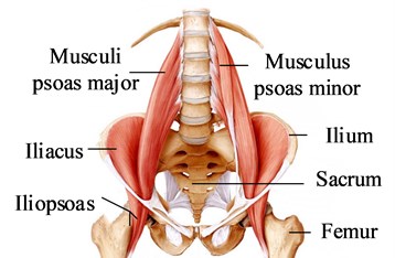
Fig. 2Skeletal muscle model PA-MTM
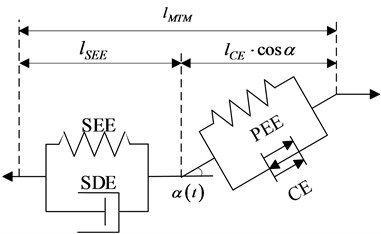
The muscle contractility model can be expressed as:
where is the force generated by the contraction unit, is the force generated by the parallel elastic unit, is the angle between muscle fiber and tendon, is the force generated by the series elastic unit, and is the force generated by the series damping unit.
The , , , , in Eq. (1) is determined by Eqs. (2)-(10), and the parameters related to the hip musculoskeletal model are shown in reference [20, 21]:
where, is the maximum equaling force when the length of contractile element is the optimal length of muscle fiber , is a function of the length of contractile element , is a function of the length of contractile element and the degree of activation , is a function of the degree of activation :
where , , , , and:
According to the force balance Eq. (1) composed of muscle fiber and tendon unit, the quadratic equation of one variable about the contraction speed of muscle fiber can be obtained: :
Solve the quadratic equation of one variable Eq. (14) to get:
were , , , , are obtained by replacing , with , .
Based on the theoretical analysis of the muscle force according to the PA-MTM skeletal muscle model, it can be known that the muscle force is related to the length of the muscle, the speed of muscle contraction, the degree of activation and other parameters.
2.2. Fracture reduction path
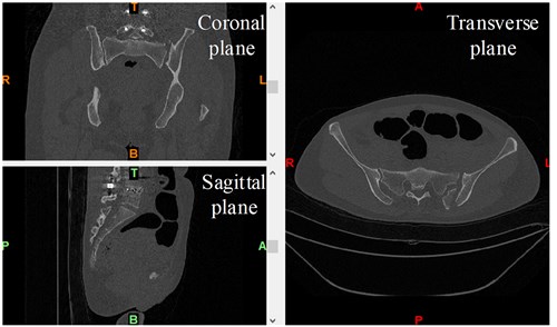
According to the CT data of the patient’s pelvic fracture, the reverse reconstruction is performed to obtain the 3D model of the pelvic fracture. CT data of pelvic fracture, as shown in Fig. 3. The model is imported into the GEOMAGIC software, the iliac bone on the affected side is registered with the mirror iliac bone on the healthy side, and the conversion matrix is derived to determine the fracture deviation. The 3D model of the registration of the iliac bone on the affected side and the mirror iliac bone on the healthy side of the pelvic fracture, as shown in Fig. 4, is the origin of the reference coordinate system .
Fig. 3CT data of pelvic fracture
The displacement deviation and rotation deviation of pelvic fracture are obtained according to the transformation matrix of iliac bone registration on the affected side. In the pelvic fracture model analyzed in this paper, under the reference coordinate system , the displacement deviations of the distal end of the fracture compared with the proximal end of the fracture along the , and axes are 3.13 mm, –4.30 mm and –8.51 mm respectively, and the rotation deviations around the , and axes are –4.90°, –6.36° and –4.83°, respectively.
According to the displacement deviation and rotation deviation of the pelvic fracture, the 3D A* algorithm is used to plan the reduction path. The result of planned reduction path is shown in Fig. 5. is the reduction start point and is the reduction end point.
2.3. Muscle force calculation of the circumpelvic main muscles
In the reduction of pelvic fractures, the main muscles that affect the reduction force of pelvic fractures are the gluteus maximus, the gluteus medius, the gluteus minimus, the m.obliquus externus abdominis, the m.obliquus internus abdominis and the iliacus. Since the gluteus maximus, gluteus medius, and gluteus minimus are muscles with wide attachment points, three points are used to mark the attachment points of the muscles to illustrate the respective functions of muscle fibers in different parts of the muscles. According to the position of hip muscle attachment points [22], the attachment points and action lines of each muscle are determined, as shown in Fig. 6.
Fig. 4Mirror-image healthy side registration model of pelvic fracture
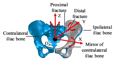
Fig. 5Planned reduction path
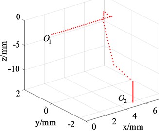
Fig. 6The attachment points and action lines of the muscle
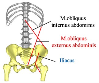
a) Anterior view
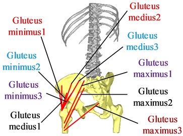
b) Posterior view
Firstly, assuming initial conditions , the initial length of the muscle is determined according to the coordinates of the starting and ending points of the muscle, relevant parameters of the muscle[23] and the degree of activation are determined, and then the initial muscle fiber length of the muscle can be obtained by the force balance Eq. (1). Then, calculating the other unknowns:, , , , , , , , , , , to get the initial muscle forces .
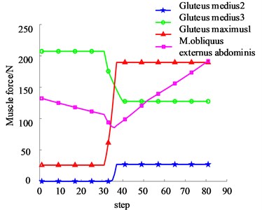
According to the result of planned path, the length of each muscle in the reduction process is determined. Then, according to the Eq. (1-14) derived from the theoretical analysis of muscle force, muscle force in the reduction process is calculated. According to the skeletal muscle attachment points and the fracture types of this model, the main muscles that affect the reduction force of the pelvic fracture types in this paper are gluteus medius 2, gluteus medius 3, gluteus maximus 1, and m.obliquus externus abdominis. Muscle force generated by each muscle during reduction is shown in Fig. 7. It can be seen from the figure that: gluteus medius 3, gluteus maximus 1, and m.obliquus externus abdominis play a major role in the reduction process. The maximal force generated by gluteus medius 3, gluteus maximus 1, and m.obliquus externus abdominis during the reduction process are 207.32 N, 189.59 N, and 191.53 N, respectively, while gluteus medius 2 has the least force.
Fig. 7The muscle force during reduction process
3. Analysis of reduction force of Tile C pelvic fracture
Pelvic fractures are generally high-energy injuries caused by falling from a high place and high-speed impact. The muscles are stimulated to produce contraction force, and combined with external forces that leads to the fracture end displacement and rotation deformation. In the process of pelvic fracture reduction, the muscle will produce tension to hinder the fracture reduction. Therefore, the fracture reduction force mainly comes from muscle force. Based on the analysis of muscle force during the reduction of pelvic fractures, this article determines the reduction force which is required for the reduction of pelvic fractures.
3.1. Reduction force analysis
Skeletal muscles that affect the reduction of Tile C pelvic fractures mainly include: gluteus medius 2, gluteus medius 3, gluteus maximus 1, and m.obliquus externus abdominis. From the anatomical diagram of human pelvis muscles, we can know the working points and directions of each muscle. In this paper, Tile C type pelvic fracture is taken as an example. Three groups of muscles that have great influence on reduction are selected and represented by four forces. Force analysis of the injured pelvis is conducted, as shown in Fig. 8.
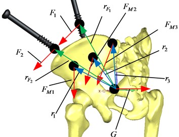
In the process of pelvic reduction, the pelvis moves at a constant speed and is in a balanced state, and the resultant force and moment are zero, then:
where, is the muscle force generated by the gluteus medius muscle 2, is the muscle force generated by the gluteus medius muscle 3, is the muscle force generated by the gluteus maximus 1, is the muscle force generated by the m.obliquus externus abdominis. is the force that the robot acts on the bone traction needle 1, is the force that the robot acts on the bone traction needle 2, and is the gravity of the pelvis; is the action point vector, is the action point vector, is the action point vector, is the action point vector, is the action point vector, is the action point vector, is the action point vector.
Fig. 8Force analysis of injured pelvis
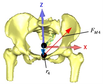
a) Anterior view
b) Posterior view
3.2. Reduction force calculation
According to the muscle force (Eqs. (1-14)) of each muscle and the reduction force (Eq. (15)) during the reduction process, total reduction force and component reduction force along the , , directions, as shown in Fig. 9.
Fig. 9Total reduction force and component reduction force during reduction process
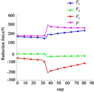
It can be seen that in the process of pelvic fracture reduction, the reduction force along the transverse direction of the pelvis (i.e. the direction) is the largest, the maximum value is 238.82 N, and the maximum fracture reduction force is 301.67 N. In the process of pelvic fracture reduction, the reduction force changes with the change of muscle length. The longer the muscle length is, the greater the muscle force and reduction force are.
4. Finite element analysis of musculoskeletal tissue with bone traction needle in different spatial position and orientation
When the spatial position and orientation of the bone traction needle is different, the biomechanical properties of pelvic musculoskeletal tissue including bone traction needle are different. The finite element method is used to compare the effects of different application points and different position and orientation of bone traction needles on the reduction stability, and to determine the application points and position and orientation of bone traction needles inserting into the pelvis, which provides a reference for selecting the suitable application points and insertion positions of pelvic fracture reduction robots.
4.1. Finite element model of pelvic musculoskeletal tissue
Using the pelvic CT scan data, the inverse modeling technique is used to reconstruct the 3D digital model of the damaged Tile C type pelvic musculoskeletal tissue in the Mimics software. The reconstruction process of musculoskeletal model is shown in Fig. 10. The established 3D digital model of pelvic musculoskeletal tissue is shown in Fig. 11.
The pelvis musculoskeletal assembly model is imported into the finite element software ANSYS20.0 in the format of x_t, and the material attributes of each pelvic tissue are assigned, as shown in Table 1. The tetrahedral elements are used to divide the grid, and the number of elements and nodes of the pelvis musculoskeletal model is 292514 and 436917.
Fig. 10Musculoskeletal model modeling process
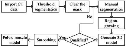
Fig. 113D digital model of pelvic musculoskeletal tissue
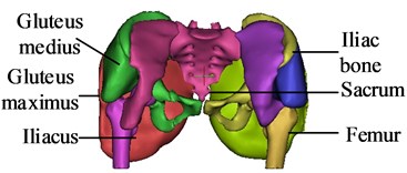
Table 1Material properties of pelvis 3D finite element model
Name | Parameter | Value |
Bone | Elastic modulus / MPa | 7300 |
Poisson ratio | 0.3 | |
Density / kg·m-3 | 2000 | |
Bone traction needle | Elastic modulus / MPa | 110000 |
Poisson ratio | 0.3 | |
Density / kg·m-3 | 2770 | |
Muscle | C10 / MPa | 0.08556 |
C01 / MPa | –0.05841 | |
C20 / MPa | 0.039 | |
C11 / MPa | –0.02319 | |
C02 / MPa | 0.00851 | |
D1 / MPa-1 | 3.6527 |
4.2. Different spatial position and orientation of bone traction needles
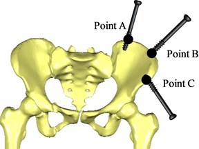
When a pelvic fracture is reduced, two bone traction needles are usually inserted into the affected side to pull the bone. According to doctors' clinical experience in the reduction of pelvic fractures [4], the bone traction needle is inserted into the pelvic bone 70 mm at three entry points A, B and C, respectively, and the spatial position and orientation of two bone traction needles are inserted into pelvic, as shown in Table 2 and Fig. 12.
Table 2Intra-needle position of bone traction needle
Entry point | Needle position | Needle direction |
Point A | Iliac crest | Iliac crest point to the top of acetabulum |
Point B | Iliac tubercle | Iliac nodules point to the acetabulum top |
Point C | Anterior inferior iliac spine | Anterior inferior iliac spine point to posterior superior iliac spine |
Fig. 12Position of bone traction needle inserted into the pelvic
4.3. Simulation analysis of the application point of reduction force
The possible position of the bone traction needles inserted into the pelvis is point A, point B or point C. The pelvis with two bone traction needles inserted in different positions was divided into group AB, AC and BC. Then, the finite element analysis of the pelvic musculoskeletal model with bone traction needles is compared.
The loading and boundary conditions are as follows: three positions , and are selected on the bone traction needle in group AB, respectively, and the maximum reduction force is applied. The force points are shown in Fig. 13. In order to approach the anatomical state of pelvic fracture reduction, the proximal femoral section and the sacroiliac joint on the healthy side are fixed and restrained, limiting 6 DOF in the direction, and then the static analysis of pelvic fracture reduction with bone traction needle is performed. The force applied at position of group AB is set as group AB1, and the finite element analysis results of group AB1 are shown in Fig. 14. The force applied at the position of group AB is set as group AB2, and the finite element analysis results of group AB2 are shown in Fig. 15. The force applied at position of Group AB is set as Group AB3, and the finite element analysis results of Group AB3 are shown in Fig. 16.
Fig. 13Different force points Si
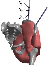
Fig. 14Finite element analysis results of AB1 group
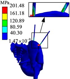
a) Stress diagram
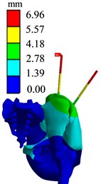
b) Displacement diagram
Fig. 15Finite element analysis results of AB2 group
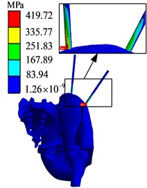
c) Stress diagram
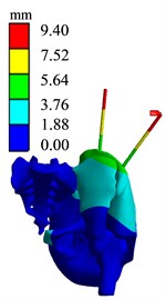
b) Displacement diagram
Fig. 16Finite element analysis results of AB3 group
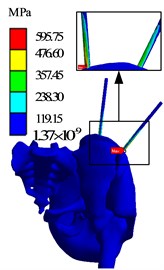
d) Stress diagram
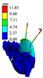
b) Displacement diagram
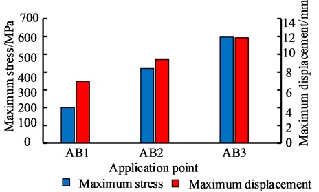
The simulation results of different force applying point of the bone traction needle are shown in Fig. 17. The maximum stresses at the needlebone interface in AB1, AB2 and AB3 groups are 210.48 MPa, 419.72 MPa and 595.75 MPa, respectively; The maximum displacements of AB1, AB2 and AB3 groups are 6.9612 mm, 9.4036 mm and 11.85 mm respectively. In terms of strength and stiffness, the pelvic stability is AB1 group > AB2 group > AB3 group. When pelvic fracture is reduced, the force point of reduction force on bone traction needle is point.
Fig. 17Comparison of maximum stress and maximum displacement of different force points
4.4. Simulation analysis of different spatial position and orientation of bone traction needle
According to the determined force point , the spatial position and orientation of the bone traction needle inserted into the pelvis during the pelvic fracture reduction is compared and analyzed.
The loading and boundary conditions are as follows: the maximum reduction force of 301.67 N is loaded at the application point of bone traction needle in AC group and BC group, respectively. The fixation constraints are carried out at the proximal femur section and the sacroiliac joint on the healthy side, limiting 6 degrees of freedom. Then, the finite element simulation of the pelvic musculoskeletal tissue with two bone traction needle is performed. Finite element analysis results of AC1 and BC1 groups are shown in Fig. 18 and Fig. 19.
Fig. 18Finite element analysis results of AC1 group
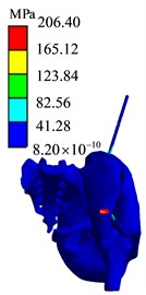
e) Stress diagram
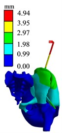
b) Displacement diagram
Fig. 19Finite element analysis results of BC1 group
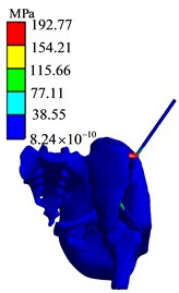
f) Stress diagram
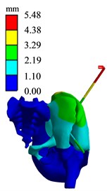
b) Displacement diagram
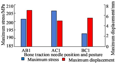
The simulation analysis results of the position and orientation of the bone traction needle are shown in Fig. 20. The maximum stresses of AB1 group, AC1 group and BC1 group are located at the interface of needle bone and are 210.48 MPa, 206.4 MPa and 192.77 MPa, respectively. The maximum displacements of AB1, AC1 and BC1 are 6.9612 mm, 4.943 mm and 5.4761 mm, respectively. The maximum stress values around two bone traction needles in AB1 group are 210.48 MPa and 120.89 MPa, the maximum stress values around two bone traction needles in AC1 group are 206.40 MPa and 165.12 MPa, the maximum stress values around the two bone traction needles in BC1 group are 192.77 MPa and 192.77 MPa. So the maximum stresses difference between bone needles and their surrounding of AB1, AC1 and BC1 group are 80.59 MPa, 41.28 MPa and 0 MPa. From three aspects of strength, stiffness and stress distribution uniformity, the stress state of the pelvis with bone traction needle is the best in the BC group under the action of reduction force. When the pelvic fracture is reduced, the best positions of the bone traction needle are point B and point C.
Fig. 20Comparison of maximum stress and maximum displacement of bone traction needle in different position and orientation
5. Conclusions
This paper mainly studies the different spatial position and orientation of the bone traction needle in the pelvis, and uses the finite element method to compare and analyze the biomechanics of the musculoskeletal tissue during the pelvic fracture reduction. The study can determine the reasonable spatial position and orientation of the bone traction needle in the pelvis.
1) Firstly, a new PA-MTM model considering the pinnate angle of skeletal muscle is proposed to analyze the muscle force. Muscle force is related to muscle length, contraction speed, degree of activation and other parameters, and the reduction force mainly comes from muscle force. According to the muscle force, the reduction force is calculated.
2) Secondly, for the pelvic fracture reduction, the suitable force point on bone traction needle is S1 point. The closer the distance from the force point to the needle-bone interface is, the more stable the pelvic biomechanic is.
3) Thirdly, for the pelvic fracture reduction, the suitable spatial position and orientation of the bone traction needle are from the iliac crest (point B) to the top of the acetabulum, and from the anterior inferior iliac spine (point C) to the posterior superior iliac spine.
References
-
Zhang Gongzi, “Research and development of minimally invasive reduction system for pelvic fracture and its preliminary application,” (in Chinese), Medical College of Chinese People’s Liberation Army, 2018.
-
Wang Tao et al., “Surgical treatment of unstable pelvic fractures associated with acetabular fractures,” (in Chinese), Chinese Journal of Bone and Joint Injury, Vol. 27, No. 12, pp. 1069–1071, 2012.
-
Fan Xiaohai et al., “Intraoperative reduction techniques for the treatment of unstable pelvic fractures,” (in Chinese), Chinese Journal of Bone and Joint Injury, Vol. 28, No. 10, pp. 946–947, 2013.
-
Song Hu, “Finite element analysis and effect observation of external fixator combined with SIJ screw in the treatment of unstable pelvic fracture guided by the principle of balance of bones and muscles,” (in Chinese), Hubei University of Traditional Chinese Medicine, 2019.
-
Tang Jingli et al., “Clinical comparative analysis of Starr-assisted reduction INFIX or anterior column screw fixation for unstable pelvic fractures,” Journal of Traumatic Surgery, Vol. 21, No. 1, pp. 9–13, 2019, https://doi.org/10.3969/j.issn.1009-4237.2019.01.003
-
J.-X. Zhao et al., “Early experience with reduction of unstable pelvic fracture using a computer-aided reduction frame,” BioMed Research International, Vol. 2018, pp. 1–7, 2018, https://doi.org/10.1155/2018/7297635
-
K. Jäckle et al., “Anatomic reduction of the sacroiliac joint in unstable pelvic ring injuries and its correlation with functional outcome,” European Journal of Trauma and Emergency Surgery, Sep. 2020, https://doi.org/10.1007/s00068-020-01504-z
-
Feng Yongzeng et al., “Clinical efficacy study of minimally invasive percutaneous cross screw internal fixation for Day type Ⅱ crescent fracture and dislocation of pelvis,” (in Chinese), Modern Chinese Doctor, Vol. 58, No. 34, pp. 80–84, 2020.
-
Guo Shuo and Guo Zheng, “Research progress of orthopedic surgical robot,” (in Chinese), Armed police medical, Vol. 29, No. 10, pp. 987–990, 2018, https://doi.org/10.14010/j.cnki.wjyx.2018.10.020
-
Xu Jiufeng et al., “Pelvic reduction robot: an experimental study,” (in Chinese), Chinese Journal of Bone and Joint Surgery, Vol. 8, No. 3, pp. 242–245, 2015, https://doi.org/10.3969/j.issn.2095-9958.2015.03-011
-
H.-S. Liu, S.-J. Duan, S.-D. Liu, F.-S. Jia, L.-M. Zhu, and M.-C. Liu, “Robot-assisted percutaneous screw placement combined with pelvic internal fixator for minimally invasive treatment of unstable pelvic ring fractures,” The International Journal of Medical Robotics and Computer Assisted Surgery, Vol. 14, No. 5, p. e1927, Oct. 2018, https://doi.org/10.1002/rcs.1927
-
A. T. M. Phillips, P. Pankaj, C. R. Howie, A. S. Usmani, and A. H. R. W. Simpson, “Finite element modelling of the pelvis: inclusion of muscular and ligamentous boundary conditions,” Medical Engineering and Physics, Vol. 29, No. 7, pp. 739–748, Sep. 2007, https://doi.org/10.1016/j.medengphy.2006.08.010
-
Wang Chengyou, “Research on Modeling Method of Hip Joint,” (in Chinese), Harbin University of Science and Technology, 2014.
-
M. Wang, R. Li, and J. Jing, “Establishment and application of lower limb finite element model based on muscle groups,” Journal of Mechanics in Medicine and Biology, Vol. 18, No. 8, p. 1840024, Dec. 2018, https://doi.org/10.1142/s0219519418400249
-
P. Hu et al., “Biomechanical comparison of three internal fixation techniques for stabilizing posterior pelvic ring disruption: a 3D finite element analysis,” Orthopaedic Surgery, Vol. 11, No. 2, pp. 195–203, Apr. 2019, https://doi.org/10.1111/os.12431
-
Esmat Elabjer, Vasilije Nikolić, Aljosa Matejcić, Marin Stancić, and Biljana Kuzmanović Elabjer, “Analysis of muscle forces acting on fragments in pelvic fractures,” Collegium Antropologicum, Vol. 33, No. 4, pp. 1095–1101, Dec. 2009.
-
I. Georgilas, G. Dagnino, P. Tarassoli, R. Atkins, and S. Dogramadzi, “Preliminary analysis of force-torque measurements for robot-assisted fracture surgery,” in 37th Annual International Conference of the IEEE Engineering in Medicine and Biology Society (EMBC), Vol. 2015, Aug. 2015, https://doi.org/10.1109/embc.2015.7319491
-
Xu Ke et al., “Experimental study on elastic traction device to assist reduction of pelvic fracture,” (in Chinese), Beijing Biomedical Engineering, Vol. 38, No. 2, pp. 126–133, 2019.
-
Zhu Qing, “Research on robotic-assisted femoral shaft fracture reduction system based on compliant actuator,” (in Chinese), Southeast University, 2018.
-
M. Günther, S. Schmitt, and V. Wank, “High-frequency oscillations as a consequence of neglected serial damping in Hill-type muscle models,” Biological Cybernetics, Vol. 97, No. 1, pp. 63–79, Jul. 2007, https://doi.org/10.1007/s00422-007-0160-6
-
D. F. B. Haeufle, M. Günther, A. Bayer, and S. Schmitt, “Hill-type muscle model with serial damping and eccentric force-velocity relation,” Journal of Biomechanics, Vol. 47, No. 6, pp. 1531–1536, Apr. 2014, https://doi.org/10.1016/j.jbiomech.2014.02.009
-
Shan Damao, “Function and significance of the mark of muscle origins and terminations – Ascertaining the compendiary center of the mark of muscle origins and terminations in lower limbs,” (in Chinese), Journal of Shandong Institute of Physical Education, No. 4, pp. 62–64, 2004, https://doi.org/10.3969/j.issn.1006-2076.2004.04.021
-
E. M. Arnold, S. R. Ward, R. L. Lieber, and S. L. Delp, “A model of the lower limb for analysis of human movement,” Annals of Biomedical Engineering, Vol. 38, No. 2, pp. 269–279, Feb. 2010, https://doi.org/10.1007/s10439-009-9852-5
Cited by
About this article

This work was supported by the National Key R&D Program of China under Grant 2020YFB1313803.
