Abstract
For the smooth blasting method, the straight parallel hole cutting method, single wedge hole cutting method and double wedge hole cutting method have been devised. Corresponding to the devised cutting methods, the blasting test have been carried out in site. By the blasting vibration monitor technology, the blasting effect and peak blasting vibration velocity have been considered and compared. From the points of blasting footage, half hole ratio of the peripheral hole, rock slag throwing distance and the homogenization degree of rock slag, the blasting effect has been assessed separately. In advance, for straight parallel hole cutting, there is a rather higher ratio in the low frequency band area, the Power Spectral Density (PSD) mainly concentrated in the range of 0-100 Hz. However, for the wedge hole cutting, the PSD mainly ranges from 0 to 800 Hz, concentrated in a higher frequency band area. Meantime, for straight parallel hole cutting, the overall energy distribution is in the low frequency part, and the distribution difference is a bit large. For the single wedge hole cutting, about 25 % of the energy in the second layer is concentrated in the range of 1000-2000 Hz. In the third layer, about 20 % of the energy is concentrated in the range of 1500-2000 Hz. Furthermore, for the double wedge hole cutting, the energy distribution is basically uniform, and there is equivalent vibration energy distribution in each frequency band. In the second layer, about 50 % of the energy is concentrated in the high frequency part, that is in the 1000-2000 Hz. Even in the range of 1750-2000 Hz, there is about 20% of the energy still distributed here.
Highlights
- The blasting effect and peak blasting vibration velocity have been considered and compared. From the points of blasting footage, half hole ratio of the peripheral hole, rock slag throwing distance and the homogenization degree of rock slag, the blasting effect has been assessed separately.
- For the wedge hole cutting, the PSD mainly ranges from 0 to 800Hz, concentrated in a higher frequency band area.
- For the double wedge hole cutting, the energy distribution is basically uniform, and there is equivalent vibration energy distribution in each frequency band.
1. Introduction
Drilling and blasting is the main excavation method, which is highly applied in the construction of highway, railway, hydraulic tunnel and underground engineering, etc. Especially, the damage of seismic wave generated by blasting in shallow tunnel to the buildings near the surface has become an urgent problem to be solved in the construction process [1, 2]. Because the main frequency of blasting vibration wave is generally low, which is similar to the surrounding facilities, then it may cause resonance and have a negative impact on the surrounding facilities. Therefore, blasting vibration monitor and its signal analysis is the key point to control the blasting hazards [3-5].
Traditional Fourier analysis only takes the vibration signal into frequency domain without considering the time domain information, which is rather suitable for the analysis of deterministic signals with simple frequency components. While the blasting vibration signal is a typical non-stationary signal, and the frequency domain analysis method is not applicable. Wavelet analysis, which can represent time-frequency information, has gradually become the main method to process blasting vibration signals.
Wavelet transform has been widely used in the blasting vibration signals processing because of its high resolution and adaptability, as well as its ability to characterize the local property of signals in time and frequency domains [6, 7]. However, the technology of blasting vibration signals processing by wavelet transform is still in its infancy [8-10].
Wavelet theory was used to determine the actual delay time of millisecond blasting, meanwhile the influence of different blasting parameters on the main frequency, blasting vibration velocity and blasting energy’s distribution were studied [11, 12]. Also, wavelet method was applied in the energy analysis of blasting vibration response [13, 14]. However, because the frequency band of the signal can only be divided exponentially and equidistantly by wavelet transform, its frequency resolution in high frequency band is rather poor [15].
High frequency part without subdivision is further decomposed by wavelet packet analysis, which can adaptively select the corresponding frequency band according to the characteristics of the analyzed signal and match it with the signal spectrum, thus the time-domain resolution is improved [16, 17]. The blasting vibration signal at the designated point of frozen rock wall has been obtained through the shaft blasting test with db6 wavelet basis [18], and the energy distribution of different frequency bands of has been analyzed. Also, the influence of elevation difference and equivalent distance on the energy attenuation of the vibration signal has been researched deeply.
Based on the measured blasting vibration data in situ, the decomposition and reconstruction of wavelet packet method has been applied here to discuss the propagation, attenuation and distribution of the seismic waves from the perspective point of energy. Meantime, from the views of blasting footage, half hole ratio of the peripheral hole, rock slag throwing distance and the homogenization degree of rock slag, the blasting effect has been assessed separately.
2. Principle of energy spectrum analysis by wavelet packet
2.1. Wavelet packet analysis
For the wavelet analysis, the signal is decomposed into two parts, i.e. low frequency part and high frequency part. In the next decomposition, only the low frequency part is decomposed again, and so on until the decomposition is completed. It could be clear that the resolution of low-frequency wave is higher than that of high-frequency wave in the wavelet decomposition, which results in a low resolution of high-frequency part of the wave. However, in the process of wavelet packet, each decomposition round not only the low-frequency part is decomposed in turn, but also the high-frequency part would be decomposed. Therefore, the resolution of the wave in high frequency band has been improved by the wavelet packet analysis method, which is more precise than the traditional wavelet analysis method [19-21].
The data acquisition of blasting vibration adopts TC-4850 blasting vibrometer. The recording time of signal is 2 second, the acquisition frequency is 2KHz, and the Nyquist frequency is 1KHz. The data can be decomposed into 8 layers using the wavelet packet decomposition method. After the first layer decomposition, the data can be divided into two parts: low-frequency SA0 (0, 500 Hz) and high-frequency SA1 (500 Hz, 1000 Hz). The second layer is to further decompose the SA0 and SA1, and to decompose SA0 into low-frequency SB0 (0,250 Hz) and high-frequency SB1 (250 Hz, 500 Hz), and to decompose SA1 into low-frequency SB2 (500 Hz, 750 Hz) and high-frequency SB3 (750 Hz, 1000 Hz) and so on. When it is decomposed into layer 8, SH0 (0, 3.906 Hz), SH1 (3.906 Hz, 7.813 Hz), SH2 (7.813 Hz, 11.718 Hz) could be obtained up to SH255 (999.094 Hz, 1000 Hz).
2.2. Principle of energy spectrum analysis
For the blasting vibration signal , sub-bands could be obtained in the layer through decomposition. Then can be expressed as [22, 23]:
In the formula, the blasting vibration signal is decomposed into the reconstructed signal on node for the layer by wavelet packet. If the frequency width of signal is , the frequency width of each sub-band in layer is equal to .
For energy , corresponding to signal , it would be:
In which, is the amplitude of discrete points , and is the acquisition number of blasting vibration signal.
From Eq. (2), the total energy of blasting vibration signal is obtained as follows:
When the signal is decomposed into layer, the ratio of the energy of each frequency band to the total energy of the signal could be as follows:
3. Blasting test of different cutting method
3.1. Principle of cutting way
The emulsion explosive is used for the blasting here. Each volume explosive weight is 0.3 kg. Meantime, each cycle footage has been kept the same as about 2000 mm. A millisecond delay with non-electric detonator is used to detonate. The cutting holes adopt continuous coupling charge, the auxiliary holes and the bottom holes adopt continuous non-coupling charge, the surrounding holes adopt the air interval with non-coupling charge to bind the interval of the explosive to the detonator. The blockage length of the surrounding hole and auxiliary hole is not less than 20 cm, while the cutting hole is not less than 40 cm.
The maximum value of blasting vibration velocity generally appears at the position of maximum tensile stress, while the position of maximum tensile stress of excavation roadway is generally at the top of roadway. Therefore, one of the vibration velocity sensors has been installed at the top of roadway to estimate the distribution of vibration intensity on the roadway excavation section.
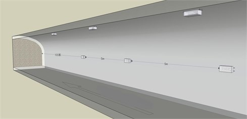
Based on the above analysis, it is considered that the blasting vibration speed at the top of the roadway is the largest. It means that the top vibration resistance of the roadway is the worst. Therefore, there are three blasting vibration velocity sensors are arranged on the top of the roadway, and the sensor is arranged at the side wall of the roadway at the same position. In which, a three direction sensors are placed at each measuring point, corresponding to the radial, vertical, and tangent directions. The base is fixed on the rock surface by lime powder coupling. As it is shown in Fig. 1.
The first measuring sensor point is arranged 10 m away from the blasting face, and the other sensors are arranged at intervals of 5 m. That is, three sets of sensors and six measuring points are linearly arranged along the top and side of the roadway from the blasting face.
According to the blasting design, the cut hole is arranged at the lower position of the center of the working face. The cutting hole is the first to detonate, so the central rock would be throw out, the free face for the surrounding rock could be increased, and the blasting effect would be achieved better. The principle can be summarized as follows, most importantly, a part of rock on the working face should be broken down to make the working face form a second free face, which creates favorable conditions for the blasting of other blast holes [24]. It means that the cutting method is mainly changed while the other blasting parameters remain unchanged. At the same time, the number of boreholes and the total charge of each cutting method are kept as consistent as possible, but the space distribution of the cutting holes is different. Moreover, the distribution area of each cutting in the face is roughly the same. Finally, the number of explosive consumables used in different cutting methods is consistent. Then the testing and its results could be scientifically credible.
Fig. 1Layout diagram of blasting vibration observation point of roadway roof and side wall
The quality of cutting plays a decisive role in improving rock breaking efficiency and blasting cyclic footage. Therefore, it is necessary to select a reasonable cutting method to induce the rock completely broken to form an ideal cavity.
The selection of cutting mode is an important link, and its main purpose is to provide compensation space and free surface for the whole blasting operation. In the case of comprehensive analysis of geological conditions, environmental and equipment factors, the selection of appropriate cutting method could have a direct impact on the blasting effect. According to the different conditions of roadway section, rock properties and geological conditions, there are many kinds of cutting hole arrangement, which can be summarized into three types as follows, straight parallel hole cutting method, inclined hole cutting method and mixed hole cutting method. Here, the straight parallel hole cutting method, single wedge hole cutting method and double wedge hole cutting method have been devised as shown in Fig. 2.
3.2. Test results
The blasting footage is a main parameter for evaluating the blasting effect, as it can reflect the blasting effect intuitively. According to the pre-designed footage, which is 2 meters, the footage is 1.9 meter for the straight parallel hole cutting, and the hole utilization is about 95 %. While for the other two wedge hole cutting, the blasting footage is 1.8 meter and 1.9 meter separately. In other words, all of these cutting method designed have achieved a desirable blasting footage.
Another parameter for assessing the blasting effect is the half hole ratio of the peripheral hole. After these designed blasting test, there is no residual hole and root. Through statistical analysis, the half hole rates of peripheral hole are generally more than 90 %. It is found that the multi-stage wedge cutting can effectively expand the volume of the cutting cavity and enhance the cutting effect, especially when it face to excavate the large section and hard rock tunnel. The divisional design not only reduces the number of holes, but also ensures the excellent blasting effect.
Fig. 2Blasting scheme of different hole cutting methods (Unit: mm)
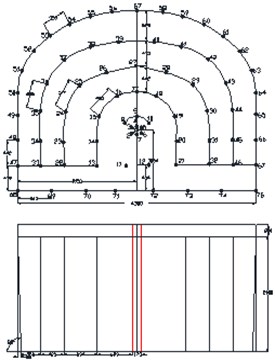
a) Parallel hole cutting scheme
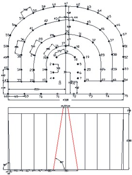
b) Single wedge hole cutting scheme
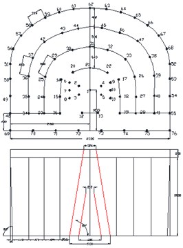
c) Double wedge hole cutting scheme
The third parameter is the rock slag throwing distance and the homogenization degree of rock slag. The adverse effects in drilling and blasting operation are too long or too short throwing distance, high rock block rate and flying rock slag impact. The volume of blasting slag pile mainly comes from the rock in the action area of auxiliary hole. A better forming quality of cutting area could reduce the clamping effect of original rock on auxiliary hole and enhance the throwing force in radial direction. Meanwhile, it could reduce the throwing force of blasting pile in the direction of roadway axis. The rock in the cutting area can be regarded as the main source of flying rock slag. The flying rock slag produced by straight parallel hole cutting is generally less than that produced by inclined hole cutting, and the throwing distance is shorter.
4. Wavelet packet analysis on blasting vibration
The blasting vibration monitor has been applied to these three cutting hole method designed, and the blasting vibration velocity could be obtained. In advance, the blasting energy attenuation would be analyzed by the wavelet packet method.
4.1. Blasting vibration velocity analysis
The typical blasting vibration signal waves of these three cutting ways are shown in Fig. 3-Fig. 5.
Fig. 3Typical blasting vibration wave of straight parallel hole cutting
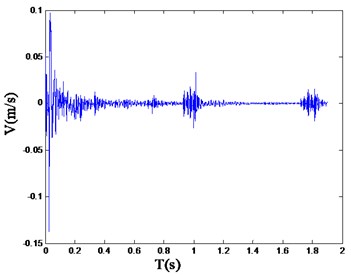
Fig. 4Typical blasting vibration wave of single wedge hole cutting
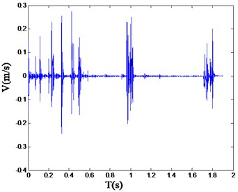
Referring to the safety allowable standard of blasting vibration velocity of various structures in “Blasting Safety Regulations” (GB6722-2015), the reasonable range of the vibration velocity should be limited under 30 cm/s. And the peak values of vibration velocity are 4.4 cm/s, 41.06 cm/s and 16.27 cm/s separately corresponding to the straight parallel hole cutting, single wedge cutting and double wedge cutting. In which, the peak value of the single wedge cutting exceeds the reasonable range [24].
It should be noticed that, for the single wedge hole cutting, the peak blasting vibration velocity has exceeded the specified value of the Regulations mentioned above. However, the blasting progress is still safe and sustainable. It is clearly elaborated that the main frequency is another parameter to assess the blasting vibration effect, along with the peak blasting vibration velocity.
Fig. 5Typical blasting vibration wave of double wedge hole cutting
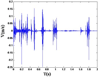
Fig. 6Power spectrum density wave of straight parallel hole cutting
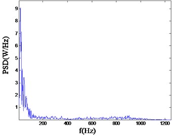
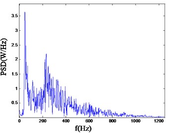
Fig. 7Power spectrum density wave of single wedge hole cutting
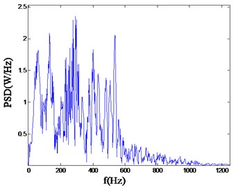
Fig. 8Power spectrum density wave of double wedge hole cutting
4.2. Spectrum analysis on blasting vibration signal
The typical power spectral density curves corresponding vibration waveforms measured with three different cutting modes are shown in the following Fig. 6-Fig. 8.
As can be seen from the above, for straight parallel hole cutting, there is a rather higher ratio in the low frequency band area, mainly concentrated in the range of 0-100 Hz. However, for the single wedge hole cutting, the PSD (power spectrum density) mainly ranges from 0 to 800 Hz. And for the double wedge hole cutting, the PSD mainly concentrated in the higher frequency range, from 0 to 800 Hz. As it is known, the lower main frequency has a more severe adverse effects to the rock and other facilities.
4.3. Blasting energy analysis
Based on the wavelet packet theory, these signals of the cutting methods are decomposed into four layers and the corresponding energy are drawn in Fig. 9-Fig. 11.
Fig. 9Energy distribution of straight parallel hole cutting by wavelet packet decomposition
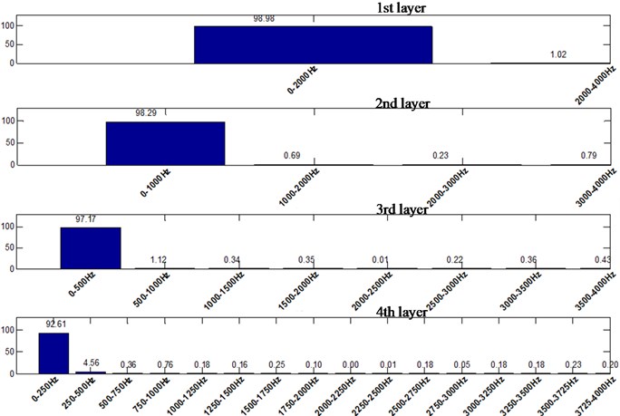
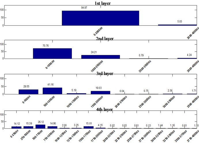
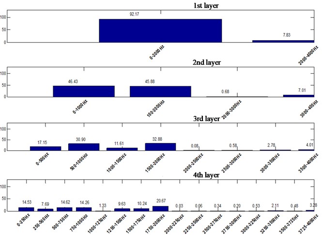
Fig. 10Energy distribution of single wedge hole cutting by wavelet packet decomposition
High frequency part of the signal can be decomposed by wavelet packet, and the decomposition is more detailed. In this way, the characteristics of different frequency components of the original signal could be analyzed by investigating the details of each sub-band, such as the energy distribution of each frequency component and the main frequency band.
Fig. 11Energy distribution of double wedge hole cutting by wavelet packet decomposition
The db3 of Daubechies wavelet series is selected to decompose the signal by the wavelet packet method. Firstly, the layer of wavelet packet decomposition must be determined. The sampling frequency set in this test is 8000 Hz. According to Shannon sampling theorem, the Nyquist frequency is 4000 Hz. Based on the principle of wavelet packet decomposition, the signal can be decomposed into 9 layers, which has 512 (= 29) wavelet packets. Each sub-band has a band width of 7.8125 Hz (= 4000/512 Hz). Then, the corresponding minimum band width is 0-7.8125 Hz, and the maximum band width is 3992.1875-4000 Hz. The energy distribution of blasting vibration signal is shown in Table 1.
Table 1Energy distribution percentage of blasting vibration signals with different cuttings (%)
Frequency (Hz) | Energy distribution percentage (%) | ||
Straight parallel hole cutting | Single wedge hole cutting | Double wedge hole cutting | |
0-7.8125 | 12.42803165 | 7.787380786 | 1.431184834 |
7.8125-15.625 | 8.385756887 | 1.166917023 | 0.280609427 |
15.625-3.4375 | 6.094989162 | 0.295469186 | 0.294487122 |
23.4375-31.25 | 10.27857362 | 0.863437309 | 0.256931048 |
31.25-39.0625 | 7.180311368 | 0.331075298 | 0.353890515 |
39.0625-46.875 | 10.09939133 | 0.140676688 | 0.293833712 |
46.875-54.6875 | 10.2157773 | 0.725965092 | 0.279176163 |
54.6875-62.500 | 3.10246656 | 0.36629761 | 0.423249932 |
62.500-70.3125 | 2.161768992 | 0.639425781 | 0.24130374 |
70.3125-78.125 | 0.177485037 | 0.096318144 | 0.276755974 |
78.125-85.9375 | 0.313251349 | 0.20576525 | 0.318293875 |
85.9375-93.75 | 2.22868617 | 0.151802148 | 0.296101735 |
93.75-101.5625 | 0.317340058 | 0.617296493 | 0.198488045 |
101.5625-109.375 | 3.179004369 | 0.159958934 | 0.149436316 |
109.375-117.1875 | 2.2725709 | 0.158657431 | 0.435862994 |
117.1875-125 | 0.220036318 | 0.114527373 | 0.343740179 |
125-132.8125 | 1.846573325 | 0.19667787 | 0.330609759 |
132.8125-140.625 | 1.430155221 | 0.227530343 | 0.288266918 |
140.625-148.4375 | 1.162957861 | 0.364889045 | 0.39495919 |
148.4375-156.25 | 1.292336295 | 0.135266024 | 0.286042253 |
156.25-164.0625 | 0.732563148 | 0.210894837 | 0.31292094 |
164.0625-171.875 | 0.661188032 | 0.207379654 | 0.304368349 |
171.875-179.6875 | 1.036478908 | 0.140918129 | 0.42282218 |
179.6875-187.5 | 0.851189968 | 0.097205295 | 0.393325931 |
187.5-195.3125 | 0.272674223 | 0.961319675 | 0.584638539 |
195.1875-203.125 | 0.307776992 | 0.330344305 | 0.446224641 |
203.125-210.9375 | 0.527767212 | 0.234988512 | 0.57437312 |
210.9375-218.75 | 0.318627571 | 0.187356376 | 0.317363842 |
218.75-226.5625 | 0.816265275 | 0.611954966 | 0.655706172 |
226.5625-234.375 | 0.638206313 | 0.247538037 | 0.371197595 |
234.375-242.1875 | 0.681989912 | 0.278642608 | 0.714945922 |
242.1875-250 | 0.83159692 | 0.162207238 | 0.36064889 |
250-257.8125 | 12.42803165 | 0.820937054 | 0.532573559 |
257.8125-265.625 | 8.385756887 | 0.166558523 | 0.252483219 |
265.625-273.4375 | 6.094989162 | 0.310912838 | 0.316596198 |
273.4375-281.25 | 0.108849399 | 0.23733022 | 0.318545999 |
281.25-289.0625 | 0.050765868 | 0.431862593 | 0.371297638 |
289.0625-296.875 | 0.049773689 | 0.245409739 | 0.486405298 |
296.875-304.6875 | 0.099747869 | 0.18991625 | 0.363871972 |
304.6875-312.5 | 0.38560565 | 0.166339565 | 0.339105092 |
312.5-320.3125 | 0.061046389 | 0.375063156 | 0.45910106 |
320.3125-328.125 | 0.053311525 | 0.28557955 | 0.545860929 |
328.125-335.9375 | 0.371814981 | 0.278342079 | 0.435025379 |
335.9375-351.5625 | 0.072747596 | 0.168340532 | 0.411026302 |
351.5625-359.375 | 0.085061554 | 0.333380002 | 0.426279182 |
359.375-367.1875 | 0.060302421 | 0.239051763 | 0.279983161 |
367.1875-375 | 0.06809924 | 0.254780878 | 0.448029822 |
375-382.8125 | 0.081040214 | 0.270129656 | 0.263535883 |
382.8125-390.625 | 0.36279637 | 1.417864314 | 0.363333188 |
390.625-398.4375 | 0.069633357 | 0.213662935 | 0.283604636 |
398.4375-406.25 | 0.067739603 | 0.291063252 | 0.263385905 |
406.25-414.0625 | 0.363972328 | 0.275318342 | 0.190018504 |
414.0625-421.875 | 0.064123476 | 0.329961157 | 0.362718483 |
421.875-429.6875 | 0.246911667 | 0.236063615 | 0.43778138 |
429.6875-437.5 | 0.039994784 | 0.31556361 | 0.325932245 |
437.5-445.3125 | 0.049982913 | 0.234589634 | 0.439676624 |
445.3125-453.125 | 0.037700281 | 0.819661957 | 0.348073342 |
453.125-460.9375 | 0.034091118 | 0.353280394 | 0.324523353 |
460.9375-468.75 | 0.234495455 | 0.212132555 | 0.271220526 |
468.75-476.5625 | 0.052573967 | 0.187167038 | 0.320462189 |
476.5625-484.375 | 0.270002258 | 0.332138932 | 0.333068414 |
484.375-492.1875 | 0.041291168 | 0.213792763 | 0.251208508 |
492.1875-500 | 0.058762114 | 0.244471176 | 0.375760774 |
500-4000 | 2.83 | 77.78 | 70.49 |
It can be seen that for straight parallel hole cutting, the main frequency of blasting vibration is lower, and the energy distribution in the high frequency range is rather narrow. The overall energy distribution is in the low frequency part, and the distribution difference is a bit large.
For the single wedge hole cutting, about 25 % of the energy in the second layer is concentrated in the range of 1000-2000 Hz. In the third layer, about 20 % of the energy is concentrated in the range of 1500-2000 Hz. In advance, for the double wedge hole cutting, the energy distribution is basically uniform, and there is equivalent vibration energy distribution in each frequency band. In the second layer, about 50 % of the energy is concentrated in the high frequency part, that is in the 1000-2000 Hz. Even in the range of 1750-2000 Hz, there is about 20 % of the energy still distributed here.
It is known that the higher the frequency distribution of blasting energy, the more conducive to blasting construction. Therefore, single wedge hole cutting and double wedge hole cutting are more conducive to blasting engineering operation. Especially for double wedge hole cutting, the energy distribution is even in the high frequency part, which should be paid attention to in hard rock engineering.
5. Discussion and suggestion
Blasting vibration monitoring should be implemented at stress concentration area such as roadway corner. The blasting parameters should be monitored in real time, the blasting effect should be identified, and the interaction and influence with surrounding environment should be analyzed, so that the blasting scheme and parameters can be adjusted in time. Pre-splitting blasting or step-by-step excavation method could be considered to reduce the impact of blasting vibration [25, 26].
With the maximum charge increases, the main frequency shows a lower frequency range. Meantime, the natural frequency of the special engineering is also low, it is obvious that this is not conducive to the safety of underground structures. Therefore, during the construction process, the blasting hole layout should be optimized, to reduce the impact of the maximum charge, especially the layout of the cutting hole.
The charge amount of surrounding hole should be strictly controlled, and the disturbance and damage of blasting to surrounding rock should be minimized. The charge quantity and delay time also should be strictly controlled, then the blasting vibration velocity could be controlled and the damage to surrounding rock would be reduced naturally.
To form an effective cutting cavity, the parameters of wedge-shaped cutting must ensure the following effects could be achieved. Firstly, a penetrating failure surface between two rows of cutting holes should be formed. Secondly, the fragmentation circles formed intersect at the bottom of the cutting hole, and the rock in the cutting cavity is fully fragmented, so that it could be separated from the rock outside. Thirdly, the force component perpendicular to the heading face is large enough to destroy the rock in the cutting cavity from the rock outside due to shearing stress. The rock in the cavity is separated and then thrown out of the working face to form an effective cutting cavity. Fourthly, the appropriate horizontal inclination angle of the cutting hole is conducive to the arrangement of the blasting hole for subsequent process, to obtain a higher utilization ratio of the blasting hole.
Furthermore, whether wedge cutting or straight-hole cutting, the parameters are not invariable. The parameters should be adjusted at any time according to the changing geological conditions of rocks in each section and cycle.
6. Conclusions
1) According to the wavelet packet transform, for straight parallel hole cutting, there is a rather higher ratio in the low frequency band area, mainly concentrated in the range of 0-100 Hz. However, for the single wedge hole cutting, the PSD mainly ranges from 0 to 800 Hz. And for the double wedge hole cutting, the PSD mainly concentrated in the higher frequency range, ranges from 0 to 800 Hz.
2) For straight parallel hole cutting, the main frequency of blasting vibration is lower, and the energy distribution in the high frequency range is rather narrow. The overall energy distribution is in the low frequency part, and the distribution difference is a bit large. For the single wedge hole cutting, about 25 % of the energy in the second layer is concentrated in the range of 1000-2000 Hz. In the third layer, about 20 % of the energy is concentrated in the range of 1500-2000 Hz. In advance, for the double wedge hole cutting, the energy distribution is basically uniform, and there is equivalent vibration energy distribution in each frequency band. In the second layer, about 50 % of the energy is concentrated in the high frequency part, that is in the 1000-2000 Hz. Even in the range of 1750-2000 Hz, there is about 20 % of the energy still distributed.
It is known that the higher the frequency distribution of blasting energy, the more conducive to blasting construction. Therefore, single wedge hole cutting and double wedge hole cutting are more conducive to blasting engineering operation. Especially for double wedge hole cutting, the energy distribution is even in the high frequency part, which should be paid attention to in hard rock engineering.
References
-
Chen Shihai et al., “Computational model and safety criterion of blasting vibration effect based on wavelet packet techniques,” (in Chinese), Explosion and Shock Waves, Vol. 30, No. 4, pp. 377–382, 2010.
-
Guan Xiaoming, Fu Hongxian, and Wang Mengshu, “Blasting vibration characteristics monitoring of tunnel under-passing hillside buildings in short-distance,” (in Chinese), Rock and Soil Mechanics, Vol. 35, No. 7, pp. 1995–2003, 2014.
-
Meng N. K., Chen Y., and Bai J. B., “Numerical simulation of directional fracturing by shaped charge blasting,” (in Chinese), Energy Science and Engineering, Vol. 8, No. 5, pp. 1824–1839, 2020.
-
D. Huang, S. Cui, and X. Li, “Wavelet packet analysis of blasting vibration signal of mountain tunnel,” Soil Dynamics and Earthquake Engineering, Vol. 117, pp. 72–80, Feb. 2019, https://doi.org/10.1016/j.soildyn.2018.11.025
-
C. González-Nicieza, M. I. Álvarez-Fernandez, A. E. Alvarez-Vigil, D. Arias-Prieto, F. López-Gayarre, and F. L. Ramos-Lopez, “Influence of depth and geological structure on the transmission of blast vibrations,” Bulletin of Engineering Geology and the Environment, Vol. 73, No. 4, pp. 1211–1223, Nov. 2014, https://doi.org/10.1007/s10064-014-0595-7
-
Lu Liang et al., “Decomposition and energy distribution of blasting vibration signal based on second generation wavelet packet,” (in Chinese), Explosion and Shock Waves, Vol. 33, No. 2, pp. 140–147, 2013.
-
Y. Gou, X. Shi, J. Zhou, X. Qiu, X. Chen, and X. Huo, “Attenuation assessment of blast-induced vibrations derived from an underground mine,” International Journal of Rock Mechanics and Mining Sciences, Vol. 127, p. 104220, Mar. 2020, https://doi.org/10.1016/j.ijrmms.2020.104220
-
He Jun, Yu Yalun, and Liang Wenji, “Wavelet analysis for blasting seismic signals,” (in Chinese), Chinese Journal of Geotechnical Engineering, Vol. 20, No. 1, pp. 47–50, 1998.
-
Lee D. W. and Kim S. H., “An analysis of the results of trial blasting of site development project in the volcanic island,” International Science Index, Civil and Environmental Engineering, Vol. 10, No. 12, pp. 1534–1539, 2016.
-
Yan Peng et al., “Identification of arriving time of vibration induced by geo-stress dynamic unloading during blasting excavation employing method of time-energy analysis based on wavelet transform,” (in Chinese), Chinese Journal of Rock Mechanics and Engineering, Vol. 28, No. 1, pp. 2836–2844, 2009.
-
Ling Tonghua and Li Xibing, “Time-energy analysis based on wavelet transform for identifying real delay time in millisecond blasting,” (in Chinese), Chinese Journal of Rock Mechanics and Engineering, Vol. 23, No. 13, pp. 2260–2270, 2004.
-
Ling Tonghua and Li Xibing, “The features of energy distribution for blast vibration signals in underground engineering by wavelet packet analysis,” (in Chinese), Explosion and Shock Waves, Vol. 24, No. 1, pp. 63–68, 2004.
-
Lou Jianwu, Long Yuan, and Xu Quanjun, “Study on the wavelet analysis applied in structure response to blasting vibration,” World Information on Earthquake Engineering, Vol. 17, No. 1, pp. 64–68, 2001.
-
Zhong Guosheng, Xu Guoyuan, and Xiong Zhengming, “Application research of the energy analysis method for blasting seismic signals based on wavelet transform,” (in Chinese), Explosion and Shock Waves, Vol. 26, No. 3, pp. 222–227, 2006.
-
Y. Sun, Q. M. Li, S. A. Mcdonald, and P. J. Withers, “Determination of the constitutive relation and critical condition for the shock compression of cellular solids,” Mechanics of Materials, Vol. 99, No. 99, pp. 26–36, Aug. 2016, https://doi.org/10.1016/j.mechmat.2016.04.004
-
M. Zhao, J. Zhang, and C. Yi, “Time-frequency characteristics of blasting vibration signals measured in milliseconds,” Mining Science and Technology (China), Vol. 21, No. 3, pp. 349–352, May 2011, https://doi.org/10.1016/j.mstc.2011.05.025
-
D. Johansson and F. Ouchterlony, “Shock wave interactions in rock blasting: the use of short delays to improve fragmentation in model-scale,” Rock Mechanics and Rock Engineering, Vol. 46, No. 1, pp. 1–18, Jan. 2013, https://doi.org/10.1007/s00603-012-0249-7
-
Shan Renliang et al., “Wavelet packet analysis of blast vibration signals of freezing shaft model,” (in Chinese), Journal of China Coal Society, Vol. 41, No. 8, pp. 1923–1932, 2016.
-
Ling Tonghua and Li Xibing, “Analysis of energy distributions of millisecond blast vibration signals using the wavelet packet method,” (in Chinese), Chinese Journal of Rock Mechanics and Engineering, Vol. 24, No. 7, pp. 1117–1122, 2005.
-
Wang Li and Wang Hailiang, “Influence of different direction vibration peak velocity of tunnel blasting on building,” (in Chinese), Blasting, Vol. 29, No. 4, pp. 6–9, 2012.
-
Xie Quanmin et al., “Blasting vibration signal analysis with wavelet and fractal portfolio analysis technique,” (in Chinese), Journal of Vibration and Shock, Vol. 30, No. 12, pp. 120–124, 2011.
-
H. Li, X. Li, J. Li, X. Xia, and X. Wang, “Application of coupled analysis methods for prediction of blast-induced dominant vibration frequency,” Earthquake Engineering and Engineering Vibration, Vol. 15, No. 1, pp. 153–162, Mar. 2016, https://doi.org/10.1007/s11803-016-0312-6
-
Zhong Guosheng, Ao Liping, and Zhao Kui, “Influence of explosion parameters on energy distribution of blasting vibration signal based on wavelet packet energy spectrum,” (in Chinese), Explosion and Shock Waves, Vol. 29, No. 3, pp. 300–305, 2009.
-
K. Man, X. Liu, J. Wang, and X. Wang, “Blasting Energy Analysis of the Different Cutting Methods,” Shock and Vibration, Vol. 2018, pp. 1–13, Dec. 2018, https://doi.org/10.1155/2018/9419018
-
Wang L. L. et al., Dynamics of materials: experiments, models and applications. London: Academic Press, 2019.
-
Wang L. L., “Some doubts in studying explosion/impact dynamics,” (in Chinese), Explosion and Shock Waves, Vol. 41, No. 1, pp. 1–9, 2021.
About this article

This work was supported by the National Natural Science Foundation of China [Grant Nos. 51522903, 51774184], Excellent project Fund in North China University of Technology [Grant No. 216051360020XN199/006] and Scientific Research Fund in North China University of Technology [Grant No. 110051360002].
