Abstract
In order to obtain the MEFP with smaller divergence angle for the apply in the destruction of unexploded ordnance, LS-DYNA numerical simulation software was used to simulate the formation process and motion state of the projectile formed by the integrated MEFP warhead. The influence of the parameters of the liner (thickness, radius of curvature) and the initiation mode (single and multi-point initiation) on the formation characteristics of MEFP were studied. After the optimization design of warhead, the simulation model of MEFP interact with shell-covered cylindrical charge was established to estimate the damage power. The optimized MEFP has small divergence angle and can detonate the shell charge with a thickness of 10 mm.
Highlights
- The forming characteristics of integrated MEFP were analyzed.
- The influence rules of the number of initiation points and parameters of the liner on MEFP parameters were obtained.
- The capability of MEFP penetrating cylindrical shell covered charge under single-point initiation mode was evaluated.
1. Introduction
Multiple explosively formed projectile (MEFP) is a kind of high-speed and stable projectile groups, which bases on the mechanism of shaped charge to crush the liner by explosive detonation and make liner overturn and deform, and then attack the target in a certain range. Compared with the general EFP warhead, it can improve the damage probability of the target, and has a great application in the field of anti-armor and anti-missile system. Richard Fong [1] carried out a lot of research on focusing on the axial deformable MEFP warhead, which formed a MEFP damage group with good directional performance with appropriate initiation mode; L. Dong [2] studied the influence of different initiation positions on the distribution of MEFP formed by cutting; Zhou [3] proposed to use several single EFP to form a combined type MEFP; Zhao [4, 5] conducted in-depth and detailed research on the integral MEFP warhead, and obtained the influence law of liner distribution spacing and explosive density on formation parameters such as projectile velocity and divergence angle. Robert P. Koch [6] using pure nickel and nickel-tungsten alloys to produce MEFP, the forming characteristics of MEFP were compared and analyzed through experiment and simulation. Song [7] adopted additive manufacturing technology to fabricated the liner of circumferential MEFP, and it was verified by experiment that MEFP could keep intact shape at 1.68 m.
For armored targets, MEFP is required to have a large divergence angle to form a wide area kill. In this paper, MEFP was innovatively adopted to destroy unexploded ordnance because of its multi fragment characteristics in specific direction and insensitivity in stand-off, which requires MEFP warhead to form dense projectile groups with small divergence angle and have enough impact initiation ability. Based on the above purpose, the computer simulation method was adopted to carry out the structural design of MEFP and the calculation of impact initiation with shell charge, so as to obtain the structural form of MEFP, which was also reliable to the initiation of shell charge in long distance, and provide a new idea for the destruction of unexploded ordnance.
2. Numerical simulation model and material parameters
2.1. Numerical simulation model
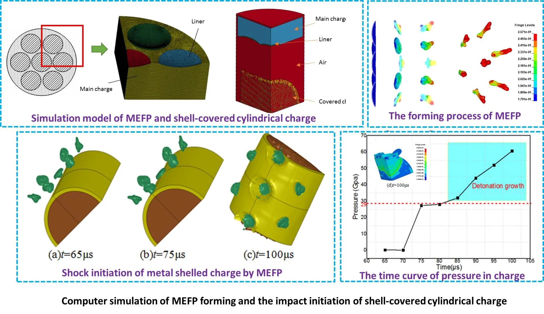
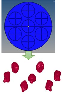
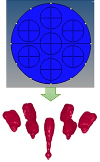
The warhead design was carried out for the integral MEFP warhead shown in Fig. 1. Its structure includes liner, explosive and initiating device. The explosive used in the warhead is B explosive. The MEFP warhead has seven spherical copper liner with the same material and size. The liner has a diameter of 60 mm and a thickness of 2.4 mm. The shell of unexploded ordnance was 10mm thickness 45# steel, filled with B explosive, the charge was 200 mm in diameter. The 8-node polyhedral solid element (solid164) was used in the calculation model. The ALE algorithm was adopted: the Euler element was used for the explosive in air domain and main explosive, the other parts were Lagrange element. A 1/4 model was established to simplify the calculation.
Fig. 11/4 finite element model of MEFP and shell-covered cylindrical charge
2.2. Material model and parameters
In order to better simulate the phenomena of liner collapsing, forming and perforating when interact with the shell charge, Johnson-cook material model with failure fracture criterion [8] was selected for liner and shell of charge, which takes into account the strain hardening, strain rate and temperature effect of material.
For von Mises yield stress model, the material yield stress is expressed as follows:
where: is equivalent plastic strain, is relative equivalent plastic strain rate, is relative temperature, is yield stress, is strain hardening, is strain hardening index, is strain rate correlation factor, is temperature correlation factor.
The expression of the fracture strain is expressed as follows:
where is the damage to a material element, is the increment of accumulated plastic strain, and is the accumulated plastic strain to failure under the current conditions of stress triaxiality, strain rate and temperature. Failure occurs when 1. Material parameters selected from reference [8].
The explosive of shaped charge was B explosive, and the HIGH_EXPLOSIVE_BURN material model and JWL equation of state were selected, see in reference [4] for specific parameters. The explosive in the shell charge adopted ELASTIC_PLASTIC_HYDRO material model and IGNITION_AND_GROWTH_OF_REACTION_IN_HE for the study on shock initiation characteristics. For air, Null material model and LINEAR_POLYNOMIAL equation of state were used. The material parameters were obtained from reference [9].
3. Analysis of numerical simulation results
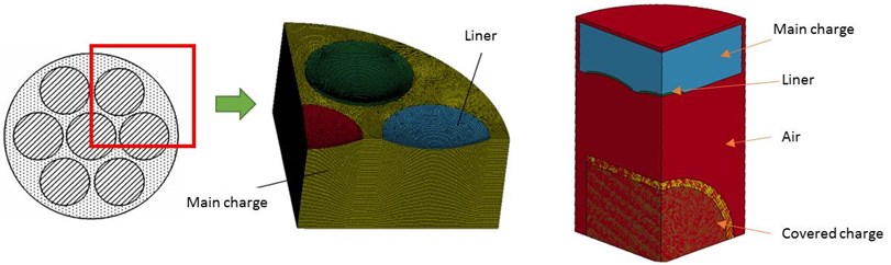
3.1. Analysis of MEFP forming process
After the warhead charge was detonated, the spherical detonation wave was generated and propagates rapidly in the charge at about 10 μs, the detonation wave began to act on the edge of the central liner at 15 μs, shown in Fig. 2. After 40 μs, the liner was gradually crushed and deformed, and turned over to form EFP. Due to the velocity gradient between the micro elements of the liner, the projectile was stretched and extended, and the velocity tended to be stable during the flight. When the effect of explosion load on the peripheral liner had not been completed, some detonation gas products had overflowed from the gap between the central and peripheral liner, causing a certain energy loss and reducing the detonation pressure.
Fig. 2The forming process of MEFP

a) 10 μs

b) 15 μs

c)20 μs

d)40 μs

e)60 μs

f)100 μs
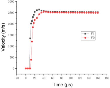
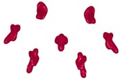
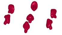
Finally, the distribution of MEFP projectiles was formed shown in Fig. 3. The integrated MEFP warhead can produce 7 shaped projectiles, which were evenly distributed in space, and the whole group of projectiles constituted a certain strike range. Fig. 4 shows the time curve of projectile velocity, in which and are the velocity of the central and peripheral EFP respectively. It can be seen that the overall velocity of the projectile reached a stable state at about 40-60 μs, and maximum velocity was about 2500 m/s.
Fig. 3Projectile distribution of MEFP (t= 200 μs)
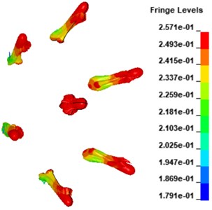
Fig. 4The time curve of EFP velocity
3.2. Analysis of influencing factors of formation of MEFP
3.2.1. Influence of curvature radius of liner
Keeping other parameters unchanged, the forming characteristics of MEFP with curvature radius of 50-80 mm were calculated. Fig. 5 shows the forming characteristics of MEFP at the time of 60 μs. Table 1 is the forming parameters of projectile with different curvature radius () of liner.
With the increase of , the divergence angle of the peripheral projectile and the velocity of the center and peripheral projectile change: when the increased from 50 to 80 mm, the ratio of length to diameter of central projectile () and the length of peripheral projectile () decreased by 83.5 % and 75.3 % respectively; the velocity of the central and peripheral projectiles ( and ) decreased by 4.1 % and 3.4 % respectively, and the divergence angle of the peripheral projectiles () increased by 5.60 %. The influence of curvature radius of liner on integral MEFP is mainly reflected in the shape change of projectile.
Table 1Forming parameters of projectile with different R1
/ mm | / cm | / m·s-1 | / m·s-1 | / (°) | |
50 | 2.49 | 4.41 | 2563 | 2473 | 9.82 |
60 | 1.21 | 2.51 | 2389 | 2389 | 9.65 |
70 | 0.63 | 1.49 | 2355 | 2300 | 9.43 |
80 | 0.41 | 1.09 | 2452 | 2387 | 9.27 |
Fig. 5The forming characteristics of MEFP under different radius of curvature
a)50 mm
b)60 mm
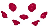
c)70 mm

d)80 mm
3.2.2. Influence of liner thickness
In order to explore the influence of liner thickness () on the performance of MEFP, the liner thickness varies from 2.4 mm to 3.6 mm were studied. Fig. 6 shows the forming characteristics of MEFP. Table 2 is the forming parameters of projectile with different liner thickness ().
When the thickness of the liner increased from 2.4 mm to 3.2 mm, the velocity of the peripheral projectile and the central projectile decreased by 16.0 % and 19.7 % respectively, the divergence angle decreased by 29.9 %. It is proved that the thickness of the liner has a great influence on the velocity divergence angle of the projectile. At the same time, it can be seen from Table 2 that with the increase of liner thickness, the length diameter ratio of the central projectile and the length of the peripheral projectile decreased. When the thickness of the liner increases from 2.4 to 3.2 mm, the length of the peripheral projectile and central projectile decreased by 25.3 % and 33.7 %, respectively.
Table 2Forming parameters of projectile with different T1
/ mm | / cm | / m·s-1 | / m·s-1 | / (°) | |
2.4 | 2.49 | 4.41 | 2563 | 2473 | 9.82 |
2.8 | 2.17 | 4.20 | 2392 | 2290 | 7.41 |
3.2 | 1.85 | 3.46 | 2217 | 2174 | 7.19 |
3.6 | 1.65 | 3.29 | 2105 | 2077 | 6.88 |
Fig. 6The forming characteristics of MEFP under different liner thickness

a)2.4 mm
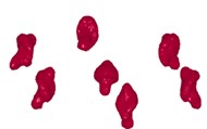
b)2.8 mm
c) 3.2 mm
d)3.6 mm
3.2.3. Influence of number of initiation points
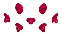
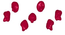
The change of the number of initiation points mainly changes the waveform of detonation wave. The collapse angle of detonation wave generated by different number and location of initiation points on the liner would be different, which may lead to great changes in the forming performance and velocity of the liner, and at the same time, the divergence angle of MEFP. The forming characteristics of MEFP under the single point, 7 points and 12 points (ring) initiation modes were calculated. Fig. 7 shows the forming characteristics of MEFP. Table 3 shows the forming parameters of projectile with different initiation point number.
With the increase of initiation point, the velocity of projectile increased greatly. In aspect of aspect ratio, the aspect ratio of the center projectile with annular initiation increased by 280 %. In the aspect of divergence angle, the divergence angle of multi-point burst was reduced by 47 %. The projectile was seriously affected by the length diameter ratio, so the single point initiation mode was considered in comprehensive analysis.
Table 3Forming parameters of projectile with different initiation points number
/ cm | / m·s-1 | / m·s-1 | / (°) | ||
Single point | 1.65 | 3.29 | 2105 | 2077 | 6.88 |
7 points | 2.17 | 3.98 | 2350 | 2287 | 3.62 |
Ring (12 points) | 6.32 | 4.27 | 3578 | 2501 | 3.42 |
Fig. 7The forming characteristics of MEFP under different initiation points number
a) Single point
b) 7 points
c) Ring (12 points)
3.3. Impact initiation of cylindrical shell covered charge subjected by MEFP
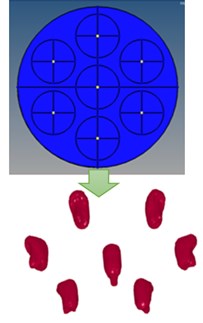
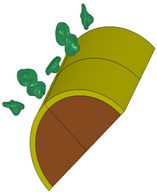
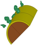
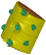
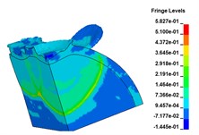
In order to evaluate the impact initiation ability of MEFP to the shell-covered charge, the numerical simulation of MEFP interact with covered charge under single initiation was carried out. Fig. 8 shows the initiation process of 10 mm thick cylindrical shell-covered charge by MEFP.
Fig. 8Shock initiation of 10mm thickness metal shelled charge by MEFP
a)65 μs
b)75 μs
c)100 μs
d)100μs
As shown in Fig. 8, a stable MEFP was formed at 65 μs. The EFP in the center collides with the metal shell at about 75 μs. Then the MEFP penetrates through the metal shell of 10 mm thickness and continues to penetrate after entering the inner charge when 100 μs. At the same time, it is found that the shell was seriously deformed at 100 μs, the depression formed on the shell was large. Because of the small divergence angle, all of the seven fragments can impact the shell-covered charge. The pressure between MEFP and metal shell was used to observe whether the internal charge detonates. The results are shown in Fig. 9 and Fig. 10.
Fig. 9The time curve of EFP velocity
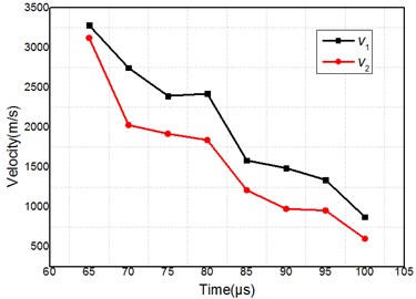
Fig. 10The time curve of pressure in charge

Though Fig. 10, we can see that at the time of 80 μs, the peak value of internal pressure was close to the initiation pressure of B explosive (29 GPa), the internal charge had been initiated. In the subsequent process, more projectiles collide with the shell covered charge, resulting in more intense detonation. The peak pressure of the internal charge continues to rise until 90 μs. The results show that the MEFP projectiles in all directions penetrate into the metal shell, and the peak pressure in shell covered charge was really high.
4. Conclusions
In this paper, MEFP was innovatively adopted to destroy unexploded ordnance, which requires MEFP warhead to form dense projectile groups with small divergence angle and have enough impact initiation ability. The analysis of MEFP forming and penetrating into shell-covered charge was carried out, the detailed process of MEFP forming was revealed, and the initiation ability of MEFP to shell-covered charge was evaluated. The conclusions are as follows:
1) The seven EFPs produced by the integrated MEFP warhead are evenly distributed in the space, and the whole projectile group constitutes a certain strike range. The speed of the copper projectile can reach more than 2500 m/s, which has strong damage ability.
2) The curvature radius of the liner mainly affects the shape of the projectile of MEFP. The larger the radius of curvature, the smaller the ratio of the length to diameter of the projectile, and the divergence angle of the projectile group decreases with the increase of the radius of curvature. The liner thickness has certain influence on the velocity and shape of the projectile. The head of the projectile formed by the large thickness cover was more dense, but the velocity of the projectile decreases with the increase of the thickness, so the thickness should be selected appropriately.
3) The MEFP formed by single point initiation could initiate 10 mm thick shell covered charge through shock initiation mechanism.
References
-
Fong R., Ng W., Tang S., Thompson L. Multiple explosively formed penetrator (MEFP) warhead technology for mine and improvised explosive device (IED) neutralization. Proceedings of the 22th International Symposium on Ballistics, 2005, p. 669-677.
-
Dong X. L., Li W. B., Chen X. J. The research about the effect of initiation point to the forming of cutting MEFP and the penetration characteristics. Materials Science and Engineering, Vol. 231, 2017, p. 012188.
-
Zhou X., Long Y., Yu D. Q., et al. Numerical simulation of multi warhead explosively formed projectile and influence factors of divergence angle. Acta Armamentarii, Vol. 27, Issue 1, 2006, p. 23-26.
-
Zhao Changxiao, Long Yuan, Ji Chong, et al. Numerical simulation and experimental study on integrated multi explosive shaped projectile warhead. Acta Armamentarii, Vol. 34, Issue 11, 2013, p. 1392-1397.
-
Zhao Changxiao, Ran Dongyue, Liu Kai, et al. Effect of charge parameters on formation of integral multiple explosively formed projectiles. Chinese Journal of Energetic Materials, Vol. 25, Issue 11, 2017, p. 882-887.
-
Koch Robert P., Snyder Jeremy, Fong Richard, et al. Using nickel-tungsten alloys to produce multiple explosively formed penetrator (mefp) warheads. Proceedings of the 30th International Symposium on Ballistics, 2017, p. 1793-1803.
-
Song Ping, Li Wenbin, Zhang Qing, et al. Experimental research on shell-liner integrated circumferential MEFP warhead based on additive manufacturing. Chinese Journal of Explosives and Propellants, Vol. 44, Issue 2, 2021, p. 219-224.
-
Johnson G. R., Cook W. H. Fracture characteristics of three metals subjected to various strains, strain rates, temperatures, and pressures. Engineering Fracture Mechanics, Vol. 21, 1985, p. 31-48.
-
LS-DYNAR Keyword User’s Manual V971.CA. Livermore Software Technology Corporation (LSTC), Livermore, 2012.
About this article

