Abstract
The attenuation characteristic of thermal shock wave in a new type of carbon phenolic (C/Ph) radiated by pulsed electron beam were studied experimentally on “FLASH II” accelerator with PVDF transducer. The attenuation trend of thermal shock wave produced by electron beam radiation in the material is calculated by means of numerical simulation. Experimental results show that: when electron beam energy fluxes are in the range of 169-531 J·cm-2 and the electron’s mean energy is about 0.6 MeV, stress at 4 mm from the irradiation surface of C/PH are in the range of 0.12-2.22GPa. The experimental results of the attenuation trend of thermal shock waves are in good agreement with the simulation results.
1. Introduction
Carbon fiber reinforced phenolic resin composite, namely carbon phenolic resin, has been widely used in aviation, aerospace, transportation, weapon components and other high-tech fields because of its high specific strength and specific stiffness, high temperature resistance, ablation resistance and other excellent properties [1, 2]. In recent years, with the development of material science and the demand of application field, new carbon phenolic materials based on modified high performance phenolic resin have been paid more and more attention. The studies are mainly focused on the fabrication, ablation mechanism and thermodynamic parameters of the C/Ph composite [3-9]. The physical and mechanical properties of this new material, especially the characteristics of thermal shock wave produced by pulse radiation, is one of the hot issues that people pay close attention to. It is of great significance for related fields to study the radiative thermal shock wave and its propagation and attenuation process of this material.
This paper mainly studies the propagation law of thermal shock wave produced by pulsed electron beam radiation in a new type of C/Ph material. The attenuation process of thermal shock wave in the target is measured by PVDF piezoelectric technique, and the results are compared with the results of numerical simulation.
2. Measuring method
Polyvinylidene fluoride (PVDF) is the principal commercially available polymer that exhibits strong piezoelectric properties. Since the discovery of piezoelectric effects in PVDF by Kawai [10], it has been widely using in the areas of impact dynamics to measure the dynamic pressure [11].
The PVDF is placed into the target assembly to directly measure the evolution of the thermal shock wave, as shown in Fig. 1. Because the self-made PVDF meter is very thin (about 40 μm), the effect on the propagation behavior of thermal shock wave can be ignored.
A resistor of 50 Ω was connected between two electrodes of the sensor. As shown in Fig. 1, the output voltage corresponding to shock pressure was recorded by the oscilloscope. The shock-induced current can be expressed as Eq. (1):
The output electric charge of a PVDF sensor was then related to the recorded voltage by the following equation:
Fig. 1A schematic diagram of PVDF instrument
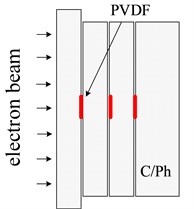
a) Target assembly
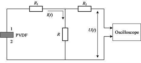
b) The measurement circuit of PVDF sensor
Calibration of the sensor usually showed a linear relationship between the electric charge and applied pressure. It is:
where is the longitudinal pressure applied on the sensor, is the electrical charge delivered by the PVDF. is the active area of PVDF film, 9 mm2. is the sensitivity constant of the PVDF sensor and its value is 33.5 pc/N.
So that combining Eqs. (2) and (3) gives:
3. Experiment and analysis
3.1. Experiment
The experiment was carried out on the “Flash II” pulsed electron beam accelerator, and each shot was equipped with a PVDF thermal shock probe. The PVDF piezoelectric probe gives signals from two to three positions each shot. Fig. 2 shows the thermal shock wave probe installed in the drift tube.
Fig. 2The thermal shock probe installed in drift tube
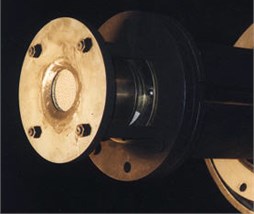
Fig. 3 shows the ablation of the material surface before and after irradiation. After the front surface of the material is irradiated by electron beam, a large amount of energy is deposited on the thin surface layer, the phenolic resin melts or vaporizes, and the carbon fiber does not melt. The vaporization of carbon fiber occurs only when its specific energy reaches sublimation energy.
Fig. 3Target before and after irradiation
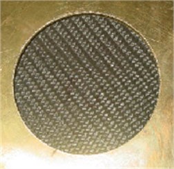
a) Target before irradiation
b) Target after irradiation
Fig. 4 shows the typical waveform recorded by PVDF and the stress waveform integrated by Eq. (4).
Fig. 4The recorded and integral waves (No. 1)
a) The recorded piezoelectric signal
b) The integral waves
3.2. Measurement results
The experimental results are shown in Table 1. is the average energy of electron beam. is the energy flux of electron beam. The uncertainty of is about 25 %.
Table 1Experimental results of thermal shock waves
No. | / MeV | / J·cm-2 | Pressure / GPa | ||
4 mm | 8 mm | 12 mm | |||
1 | 0.59 | 410 | 1.59 | 1.21 | – |
2 | 0.50 | 383 | 1.43 | 1.11 | 0.90 |
3 | 0.70 | 531 | 2.22 | 1.53 | 1.06 |
4 | 0.55 | 358 | 0.88 | 0.67 | 0.51 |
5 | 0.51 | 312 | 0.81 | 0.70 | 0.47 |
6 | 0.58 | 429 | 1.82 | 1.35 | 1.01 |
7 | 0.61 | 181 | 0.15 | – | – |
8 | 0.65 | 169 | 0.12 | – | – |
9 | 0.55 | 217 | 0.31 | – | – |
It can be seen from Table 1 that the peak intensity of thermal shock waves attenuates with the propagation distance. The higher the energy flux of the electron beam is, the greater the intensity of the thermal shock wave produced in the target is, and the relationship between them is approximately linear. As shown in Fig. 5, when electron beam energy fluxes are in the range of 169-531 J/cm2 and the electron’s mean energy is about 0.6 MeV, stress at 4 mm from the irradiation surface of C/PH are in the range of 0.12-2.22 GPa.
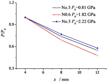
Taking several shots with same pulse width as an example, the data are normalized. As shown in Fig. 6, the higher the peak intensity of the thermal shock wave is, the faster the peak attenuation is.
Fig. 5The pressure vs. Φ curve at the position of x= 4 mm
Fig. 6Wave attenuation with different peak intensities
3.3. Analysis
Electron beams irradiate the target to deposit energy in a thin layer on the surface of the material. The higher the electron energy, the deeper the deposition depth. For the electrons of 0.6 MeV energy, the maximum depth of deposition in carbon phenolic is about 2.5 mm. Fig. 7 shows the energy deposition profiles of the electrons with different energies.
Fig. 7Energy deposition profile of electrons in C/Ph
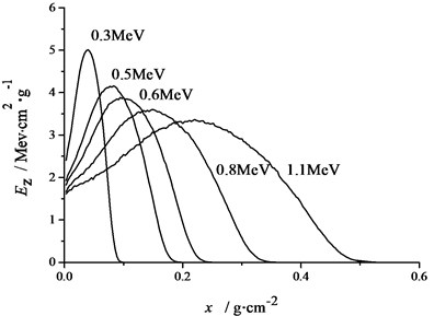
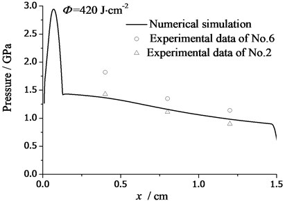
Fig. 8The attenuation curve of thermal shock
The initial stress curve caused by energy deposition is expressed by the following formula:
The compressive stress occurs at the same time as the energy deposition and is transferred from the high pressure area to the low pressure area. Non-uniform energy deposition causes compressive stress waves propagating in the material. The propagation characteristics of thermal shock waves in the target are numerically simulated by using an one-dimensional plane fluid elastoplastic model [12, 13].
Fig. 8 shows the attenuation of the thermal shock waves induced by the electron beam with average energy (0.6 MeV). The data of No. 2 and No. 6 are listed in the figure, for their energy Fluence is close to the same. It can be found that the simulation results are in good agreement with the experimental results.
4. Conclusions
Different from the most studies, we pay attention to the study of thermal shock wave propagation caused by intense pulse electron beam irradiation in C/Ph. Through experimental research and analysis, the following conclusions can be drawn:
(1) When electron beam energy fluxes are in the range of 169-531 J/cm2 and the electron’s mean energy is about 0.6 MeV, stress at 4 mm from the irradiation surface of C/PH are in the range of 0.12-2.22 GPa.
(2) At the given location in the target, the peak intensity of thermal shock wave increases linearly with the increase of electron beam energy flux.
(3) For the thermal shock wave with the same pulse width, the higher the peak intensity of the thermal shock wave is, the faster the peak value of the thermal shock wave attenuates.
(4) According to the material parameters, the peak attenuation characteristics of thermal shock waves are numerically simulated, and the simulation results are basically consistent with the experimental results. The compression wave propagates in the composite, and will be reflected from the inner free surface or adhesive layer. When the tensile wave strength exceeds the threshold of the composite, it may cause spallation failure and bond surface degumming of the material.
References
-
Luo Yongkang, Wang Weimin Carbon/phenolic thermal insulation material has been successfully developed by Beijing Institute of material Technology. Aerospace Materials Technology, Vol. 3, 1987, p. 65.
-
Li Zhongping Development and prospect of heat-resistant composites. Journal of Composite Materials, Vol. 28, Issue 2, 2011, p. 1-9.
-
Cheng Haiming, Xue Huafei, Hong Changqing, et al. Fabrication and heat-insolation of a novel low-density and low thermal conductivity carbon/phenolic composite. Rare Metal Materials and Engineering, Vol. 45, Issue 1, 2015, p. 478-481.
-
Yi Fajun, Liu Yongqing, Zhai Pengcheng, Kuang Songnian Thermal stress analysis of carbon/phenolic composites during ablation process. Journal of Harbin Institute of Technology, Vol. 40, Issue 7, 2008, p. 1081-1084.
-
Zhu Y. W., Meng S. H., Yi F. J., et al. Forecasting method for ablation behaviors of carbon/phenolic composites. Acta Materiae Compositae Sinica, Vol. 33, Issue 5, 2016, p. 984-990.
-
Zhao Te, Ye Hong, Zhang Lisong, Cai Qilin Experimental Investigation on the Specific Heat of Carbonized Phenolic Resin-Based Ablative Materials. International Journal of Thermophysics, Vol. 38, Issue 10, 2017, p. 151.
-
Francisco Torres Herrador, Jeremie Meurisse B. E., Francesco Panerai, Julien Blondeau, Jean Lachaud, Brody Bessire K., Thierry Magin E., Nagi Mansour N. A high heating rate pyrolysis model for the phenolic impregnated carbon ablator (PICA) based on mass spectroscopy experiments. Journal of Analytical and Applied Pyrolysis, Vol. 141, 2019, p. 104625.
-
Francisco Torres Herrador, Joffrey Coheur, Francesco Panerai, Thierry Magin E., Maarten Arnst, Nagi Mansour N., Julien Blondeau Competitive kinetic model for the pyrolysis of the Phenolic Impregnated Carbon Ablator. Aerospace Science and Technology, Vol. 100, 2020, p. 105784.
-
Torres Herrador Francisco, Turchi Alessandro, Van Geem Kevin M., Blondeau Julien, Magin Thierry E. Determination of heat capacity of carbon composites with application to carbon/phenolic ablators up to high temperatures. Aerospace Science and Technology, Vol. 108, 2021, p. 106375.
-
Kawai H. The Piezoelectricity of Poly (vinylidene Fluoride). Journal of Applied Physics, Vol. 8, 1969, p. 975-976.
-
Johnson D. E., Lee L. M., Hedemann M. A., et al. PVDF measurement of soft X-ray induced shock and filter debris impulse. American Institute of Physics, 1994, p. 1911-1914.
-
Lin Peng Analytical calculation of soft X-ray jet impulse. Atomic Energy Science and Technology, Vol. 47, Issue 10, 2013, p. 1878-1882.
-
Tang Wenhui, Zhang Ruoqi, Zhao Guomin Thermal shock wave induced by pulsed X-ray. Journal of High Pressure Physics, Vol. 2, 1995, p. 107-111.
About this article

