Abstract
This research presents an optimal trajectory tracking control method for improving the accuracy of 3-DOF translational parallel robots in the surgery field based on the Particle Swarm Optimization (PSO) method. The 3-DOF translational robot has three translational degrees of freedom, which consists of three arms with three revolute joints and twelve spherical joints. Firstly, the kinematics model is established; and the dynamics equation of the Robot is built by applying the Lagrange equation of the first type, and then the dynamics controller of 3-DOF translational robot is designed base on the dynamics equations. Secondly, a trajectory tracking controller model using the Particle Swarm Optimization based on inverse dynamics controlled method for 3-DOF translational Robot is designed. The control performance results of the proposed controller is evaluated by simulation and compared with the other published research results. Finally, the proposed controller can achieve better tracking performance in comparison with other controllers as Proportional Integral Derivative (PID) controller, GPI controller, and adaptive controller.
Highlights
- A trajectory tracking controller model using the Particle Swarm Optimization based on inverse dynamics controlled method for 3-DOF translational Robot
- Proportional Integral Derivative (PID) controller, GPI controller, and adaptive controllers optimization method, Integral of the Square of the Error (ISE) play an important role as objective conditions
- The IDC is a novel and effective method for 3-DOF translational robot control systems in the surgery field trajectory tracking of 3-DOF translational robot problems was implemented and optimized by used the Inverse Dynamics Control (IDC) method and Particle Swarm Optimization (PSO) algorithm
- PSO algorithm to find out the gains of controller more quick and simple than other methods
1. Introduction
The parallel mechanism robot has many good characteristics such as: high stiffness, high performance, high speed, and high accuracy. The Delta-type parallel mechanism robot, which was first proposed by Clavel are commonly used in food industrial, medical surgery and other high speed applications. Up to now, mechanical structure, kinematics, dynamics and intelligent control of Delta-type robot has been studied and developed worldwide. The kinematics of Delta robot was solved by applying vector loop equations and the dynamics equations were built by applying the Lagrangian equation of the first type [1]. Hamid D. Taghirad was discussed about kinematics, dynamics and control of parallel robot. Despite the fact that the controlling of parallel robot was mentioned, however, author have given some briefly block paragraph of controllers. These controller is applied to control planar manipulator and Stewart-Gough platform [2]. The most common control method for trajectory tracking on Delta robot is to use PID controller. To maximize appropriate workspace, Pradya Prempraneerach has researched and proposed the mechanical structure of Delta robot and using the traditional PID controller to tracking trajectory of the robot [3]. Sheng Jian et al. modeled the PMSM motor and used PID to control the motion of PMSM motor at three actuator joints of Delta robot [4], the gains of PID controller were set manual. In [5], L. Angel and J. Viola performed the trajectory tracking using two PID controller. Authors used Integer Order PID (IOPID) and Fractional Order PID (FOPID) base computed torque control technique and proposed an algorithm to find gains of the controller by using Matlab function. The fuzzy method is used by many authors in [6]-[9] to control the motion of Delta robot. Mohsen Asgari et al. performed dynamics modeling and trajectory tracking control using four methods as PD, PID, fuzzy PD, and fuzzy PID [6]. The comparison between four control method show errors of actuated joints using PID and fuzzy PID are the same (0.008rad) and less than results of PD and fuzzy PD. These errors increased in the presence of disturbance. Similarly, other researches [7]-[9] using fuzzy control show big amount of calculation and large error. Trajectory tracking of Delta robot were implemented by Neural Network based controller [10]-[13]. Similar to fuzzy method, these researches need a big amount of experimental data to train the controller. This defect lead to the increase of time to converge to the reference trajectory. It took more than 1s to reach the reference trajectory [10]. In [14]-[18] the authors applied the robust control method H∞ for motion control of Delta robot. These researches designed the H∞ robust controller and applied to the Delta robot to perform pick-and-place operation. The performance of proposed controller was compared to other controller as Computed Torque Control and PID. Simulation results show that the H∞ controller performed better than others. However, the steady state error of moving platform still exist and be unstable (maximum value more than 1mm). The Computed Torque Control technique is used in many researches [19, 20]. In this technique inverse dynamic is use to compensate nonlinear of the robot’s dynamic. This controller also called Inverse Dynamic Controller (IDC). Jianlong Hao et al. established the dynamic equation of Delta robot based on the principal of virtual work and proposed CTC to control trajectory tracking [19]. Extended CTC used extra data from additional sensors at passive joints of the Delta robot [20]. The performance of extended CTC was compared to the traditional CTC. In both researches above, the gains of controller have chosen manual. Luis Angel Castañeda et al. were designed an adaptive controller to solve the trajectory tracking problem of Delta robot with uncertain dynamical model [21]. They have simulated and compared the results with two other controller as PID and GPI. In [22], Joao Fabian presented the implementation of trajectory tracking of Delta robot using PD and LQR controller, where the PD controller parameters were obtained using pole placement. However, authors have not proposed any optimal trajectory tracking control method to manipulate the 3-DOF Translational Delta Robot type in the surrey application yet. In this research, authors focus on optimal mechanism and kinematics of 3-DOF Translational Delta Robot type to enlarge workspace by vary arm lengths. The trajectory tracking was simulated by using PID controller with various payload to demonstrate the pick-and-place operation. To optimize the trajectory of the 3-DOF translational robot, Particle Swarm Optimization method is chosen as a novel optimization trajectory tracking control for 3-DOF translational Delta robot type. PSO is a population-based optimization technique inspired by the motion of bird flocks and schooling fish. PSO shares many similarities with evolutionary computation techniques. The system is initialized with a population of random solutions, and the search for the optimal solution is performed by updating generations. In PSO, the potential solutions of particle swarm optimization for solving various kinds of optimization problems, called particles, move in the problem space by following the current optimum particles. PSO is computationally more efficient in terms of both speed and memory requirements.
This paper organizes like this: presents an optimal trajectory tracking control method for 3-DOF translational robot Delta type. The 3-DOF translational robot with three translational degrees of freedom has chosen. First of all, mechanism, kinematic and dynamic of robot are presented. Secondly, based on the dynamic of 3-DOF translational robot, an inverse dynamic controller (IDC) is designed to track a desired trajectory. To achieve the best performance of trajectory control, the Particle Swarm Optimization (PSO) is used to determine parameters of the controller. In this optimization method, Integral of the Square of the Error (ISE) play an important role as objective conditions. The simulation results are presented and compared with other control methods in the rest of this article.
2. Mathematic of kinematics and dynamics of 3-DOF translational robot
2.1. Kinematic of 3-DOF Translational robot
The 3-DOF translational robot has three arm connect the moving platform and the fixed base is shown in Fig. 1. Each arm have two parts, the upper arm is connected to the active motor using revolute joint. Each lower arm is made up of a four-bar parallelogram which connect with the moving platform and the upper arm using spherical joint. The moving platform can perform translational movement in three directions. In other words, the robot is called three translational degrees of freedom.
Fig. 13D drawing of 3-DOF translational robot
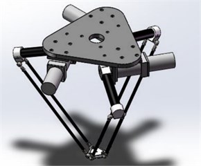
Fig. 2Vectors description of 3-DOF translational robot
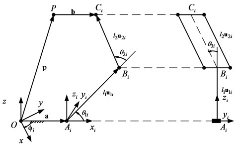
Kinematics of 3-DOF translational robot has discussed by many authors with many methods, in this study authors chose the vector loop equation method to solve this problem. In [1], authors proposed the inverse kinematics of Delta parallel robot base on vectors loop equation. Vectors of 3-DOF translational robot are illustrated in Fig. 2. As shown on Fig. 2, the vectors loop equation of parallel robot is given as follow:
Expressing Eq. (1) in the frame with yield:
where are length of lower arm and upper arm; with are actuated joint angles and passive joint angles respectively, are position of point . The position of can be obtained as:
where are position of the center point of moving platform in the coordinate system. The solutions of are found by solving Eq. (2).
Solving Eq. (2) obtained:
where .
Substituting Eq. (4) and Eq. (5) into Eq. (2):
Solving two equations above yield:
where , .
2.2. Dynamics equation of 3-DOF translational robot
In this research author using the Lagrangian formulation of the first type to solve the dynamics problems of 3-DOF translational robot. The Lagrangian function of the first type is written as [1]:
where denotes the th constraint function, is the number of constraint functions, is the Lagrangian multiplier. is the Lagrangian function. Constraint equations with are obtained from the fact that the distance between joints B and C is always equal to the length of the connecting rod of the upper arm:
Taking the derivatives of contraint functions and Lagrangian function, Lagrangian multipliers, the dynamics of 3-DOF translational robot can be written as:
where is axial moment of inertia of the rotor mounted on the th limb, is moment of lower arms, , , are mass of moving platform, lower arm and upper arm respectively Eq. (11) can be rewritten in matrix form as following:
where: is the manipulator inertia matrix, is the gravitational vector, is the vector of generalized forces, is vector of generalized Lagrange coordinates:
3. Optimization trajectory tracking controller of 3-DOF translational robot
3.1. Controller design
The dynamics Eq. (11) can be rewritten in matrices form as below:
where ,, are mass matrix, Coriolis and Centrifugal matrix, gravity vector respectively, is disturbance.
The Inverse Dynamics control law of 3-DOF transnational robot is written as [19]:
where denote the approximate estimate of the manipulator mass matrix, Coriolis and Centrifugal matrix and gravity vector in the joint space respectively; and are joint angle and joint acceleration desired; , are positive diagonal matrices.
Substituting Eq. (9) into Eq. (8) the dynamics equation of 3-DOF translational robot can be expressed as follow:
In the dynamics equation of 3-DOF translational robot thus . In real model, the and can calculated, assume that , and there is no disturbance wrench is applied to the manipulator, the error dynamic is simplified to:
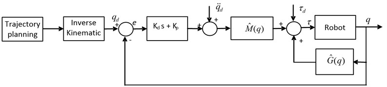
With error dynamic equation Eq. (16) above, the tracking error can be designed to convergence toward zero by choosing , appropriate. The Inverse Dynamics controller model in joint space is depicted in Fig. 3.
This section may be divided by subheadings. It should provide a concise and precise description of the experimental results, their interpretation, as well as the experimental conclusions that can be drawn.
Fig. 3Trajectory tracking inverse dynamics controller
3.2. Particle Swarm Optimization (PSO) algorithm
This paper is presented a method of choosing the parameters of the Inverse Dynamics Controller. The dynamics error equation reach to zero by choosing , gains. In this research, the authors are using the Particle Swarm Optimization method to find the optimization gains. The advantages of PSO are: simplicity and efficiency, proven in many other parameters training problems. The PSO method was developed by simulation of simplified social model, where each population is called a swarm. Each candidate, called a particle, flies through problem space to look for the optimal position, similar to food searching of bird swarm. Assume that, the search space is n-dimension, each particle corresponding to an -dimension position vector , and velocity is represented by an -dimension velocity vector, . The best previously visited position is called individual best position, . The position of the best individual of the whole swarm is called the global best position, . The velocity and position are updated at each step according to the following two equations:
where is inertia weight; , are random variables in the range of ; , are positive constant parameters called acceleration coefficients.
In this paper, the PSO was combined with the kinematic and dynamic model of 3-DOF translational robot to find out the gains of controller. The parameters was chosen as , , , , . The fitness function is the measurement of the trajectory’s quality. The objective functions applied for this particular problem is the Integral Square Error (ISE). In this case, the best position is determined by the minimum of Integral of the Square of the Error value by using Matlab toolbox. In each iteration, the gains are updated sequentially in individual best position set and global best position set corresponding to ISE value. The gains are taken after 50 iterations show the errors are acceptable as mention in simulation part below.
4. Simulation results and discussion
The simulation of kinematic, dynamic and control of the 3-DOF translational robot was implemented in Matlab/Simulink. Dynamic parameters of the robot are described in Table 1.
As mention above, corresponding to dynamic parameters of the robot, the , of the controller was found by applying the PSO method, we have:
Table 1Parameter of 3-DOF translational
Parameter | Value | Unit |
Mass of lower arm | 0.426 | kg |
Mass of upper arm | 0.069 | kg |
Mass of moving platform | 0.069 | kg |
Length of lower arm | 171.5 | mm |
Length of upper arm | 396 | mm |
Radius of fix platform | 100 | mm |
Radius of moving platform | 22.5 | mm |
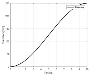
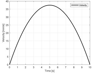
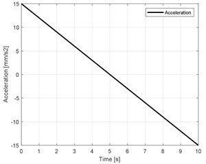
The trajectory form was designed by using the third odder polynomial as below [23]:
The coefficients of Eq. (14) are obtained by solving set of equations Eq. (15):
where , , , and , , are initial time, position and velocity respectively, , , are final time, position and velocity respectively.
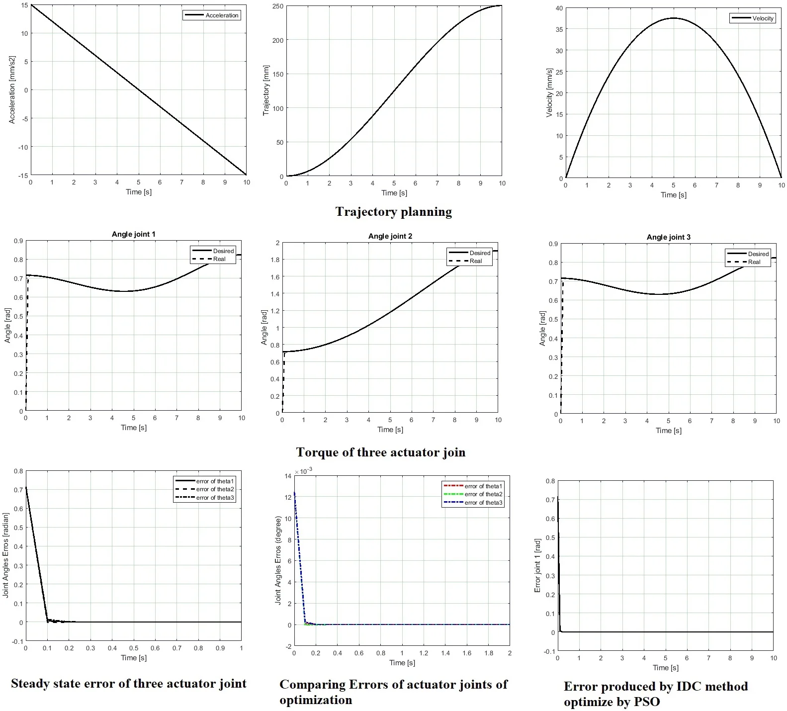
In this research, the trajectory of the moving platform is implemented in direction which relative to the coordinate system, where , 10 (sec), , 250 (mm) and , . The trajectory, velocity and acceleration are showed in Fig. 4.
Fig. 4Trajectory planning
a)
b)
c)
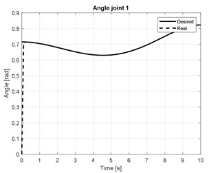
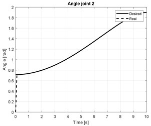
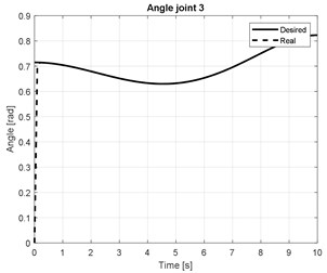
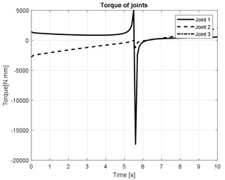
The numerical simulation results of the joint angles of three arm are shown in Figs. 5(a-c). The torque of three actuators joint are presented in Fig. (d).
Fig. 5Torque of three actuator joint
a)
b)
c)
d)
As mention at the first part, the objective condition of optimization method is integral of the square of the error . The PSO will apply to find , which corresponds to minimum of [24]:
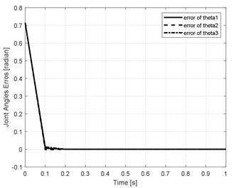
where is steady state error of actuator joint of the robot. According to parameters and the trajectory planning of the Delta robot, the steady state error of three actuators joints are showed in Fig. 6. Where 0.2555, 0.2557 respectively.
Fig. 6Steady state error of three actuator joint
The performance of proposed control method could be evaluated by compare with other methods in [21] as shown below in Fig. 7.
Fig. 7Comparing angle error with other methods
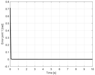
a) Error produced by IDC method optimize by PSO
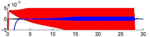
b) Red line is error produced by PID controller, blue line is error produced by GPI controller (base on extended state observer), black line is error produced by adaptive controller proposed in [21]
Fig. 7 shows the error of actuator joint 1 of the proposed controller and other controllers implemented in [21]. Fig. 7(b) shows that all results still oscillate around zero points with 0.005 rad deviation. The result of adaptive controller is the best of three methods but still restricted to a vicinity of the origin. Fig. 7(a) shows the error produced by optimization IDC is better than other methods. The graphs show that the error converges to zero after 0.2 s and the steady-state error is maintained no more than 5.10-5 rad. Another comparison can be performed between the proposed controller and the controller in [19], the graph of errors as showed in Fig. 8.
Fig. 8Comparing Errors of actuator joints of optimization a) IDC and b) PD-CTC [19]
![Comparing Errors of actuator joints of optimization a) IDC and b) PD-CTC [19]](https://static-01.extrica.com/articles/21997/21997-img14.jpg)
a)
![Comparing Errors of actuator joints of optimization a) IDC and b) PD-CTC [19]](https://static-01.extrica.com/articles/21997/21997-img15.jpg)
b) The maximum error of joints at 1 degree (0.017 rad) while in a) as mention above, the error is 5.10-5 rad
Fig. 8 show the error of three actuators joint angle of the 3-DOF translational robot. In Fig. 8(a), the error curve converges to zero after 0.1sec, and the steady state error is very small, while in Fig. 8(b), this value cannot converge to zero, even it oscillates around –1 and 1 degree. The comparisons above demonstrates the better performance of this controller in accuracy and stability.
5. Conclusions
In this paper, the trajectory tracking of 3-DOF translational robot problems was implemented and optimized by used the Inverse Dynamics Control (IDC) method and Particle Swarm Optimization (PSO) algorithm. The IDC is used to track the desired trajectory in joint space. The IDC is a novel and effective method for 3-DOF translational robot control systems in the surgery field. PSO algorithm to find out the gains of controller more quick and simple than other methods. The comparison of simulation results showed the steady-state error of the proposed method is smaller and converge to zero faster than other methods. In the future, this control method will be used to combine with other force control to improve the control of the 3-DOF translational robot in the real model.
References
-
L. W. Tsai, Robot Analysis: The Mechanics of Serial and Parallel Manipulators. New York: Wiley, 1999.
-
H. D. Taghirad, Parallel Robots. Boca Raton: CRC Press, 2013, https://doi.org/10.1201/b16096
-
P. Prempraneerach, “Delta parallel robot workspace and dynamic trajectory tracking of delta parallel robot,” in 2014 International Computer Science and Engineering Conference (ICSEC), Jul. 2014, https://doi.org/10.1109/icsec.2014.6978242
-
S. Jian and Y. Lou, “Application of motion control system for delta parallel robot,” in 2017 IEEE International Conference on Information and Automation (ICIA), Jul. 2017, https://doi.org/10.1109/icinfa.2017.8079002
-
L. Angel and J. Viola, “Fractional order PID for tracking control of a parallel robotic manipulator type delta,” ISA Transactions, Vol. 79, pp. 172–188, Aug. 2018, https://doi.org/10.1016/j.isatra.2018.04.010
-
M. Asgari, M. A. Ardestani, and M. Asgari, “Dynamics and control of a novel 3-DoF spatial parallel robot,” in 2013 First RSI/ISM International Conference on Robotics and Mechatronics (ICRoM 2013), Feb. 2013, https://doi.org/10.1109/icrom.2013.6510102
-
J. Zhang, C. Lian, R. Gao, and L. Shi, “3-Degree-of-freedom parallel robot control based fuzzy theory,” in 2010 2nd International Conference on Intelligent Human-Machine Systems and Cybernetics (IHMSC), Aug. 2010, https://doi.org/10.1109/ihmsc.2010.62
-
O. Linda and M. Manic, “Uncertainty-robust design of interval type-2 fuzzy logic controller for delta parallel robot,” IEEE Transactions on Industrial Informatics, Vol. 7, No. 4, pp. 661–670, Nov. 2011, https://doi.org/10.1109/tii.2011.2166786
-
C. E. Boudjedir et al., “Fuzzy logic iterative learning control for trajectory tracking of parallel kinematic manipulators,” in 2017 5th International Conference on Electrical Engineering – Boumerdes (ICEE-B), Oct. 2017, https://doi.org/10.1109/icee-b.2017.8192041
-
T. Uzunovic, E. Golubovic, E. A. Baran, and A. Sabanovic, “Configuration space control of a parallel delta robot with a neural network based inverse kinematics,” in 2013 8th International Conference on Electrical and Electronics Engineering (ELECO), Nov. 2013, https://doi.org/10.1109/eleco.2013.6713892
-
Y. Huang and Z. Huang, “Neural network based dynamic trajectory tracking of delta parallel robot,” in 2015 IEEE International Conference on Mechatronics and Automation (ICMA), Aug. 2015, https://doi.org/10.1109/icma.2015.7237782
-
W. Liao, W. Liang, and A. Wang, “Inverse dynamics control of a parallel robot based on RBF Neural network,” in 2017 International Conference on Advanced Mechatronic Systems (ICAMechS), Dec. 2017, https://doi.org/10.1109/icamechs.2017.8316501
-
X. Lu, Y. Zhao, and M. Liu, “Self-learning interval type-2 fuzzy neural network controllers for trajectory control of a delta parallel robot,” Neurocomputing, Vol. 283, pp. 107–119, Mar. 2018, https://doi.org/10.1016/j.neucom.2017.12.043
-
M. Rachedi, M. Bouri, and B. Hemici, “Application of an H∞ control strategy to the parallel Delta,” in 2012 2nd International Conference on Communications, Computing and Control Applications (CCCA), Dec. 2012, https://doi.org/10.1109/ccca.2012.6417912
-
M. Rachedi, B. Hemici, and M. Bouri, “Application of the mixed sensitivity problem H∞ and H2 to the parallel Delta,” in 2013 3rd International Conference on Systems and Control (ICSC), Oct. 2013, https://doi.org/10.1109/icosc.2013.6750903
-
M. Rachedi, M. Bouri, and B. Hemici, “H∞ feedback control for parallel mechanism and application to delta robot,” in 2014 22nd Mediterranean Conference of Control and Automation (MED), Jun. 2014, https://doi.org/10.1109/med.2014.6961584
-
M. Rachedi, “Model based control of 3 DOF parallel delta robot using inverse dynamic model,” in 2017 IEEE International Conference on Mechatronics and Automation (ICMA), Aug. 2017, https://doi.org/10.1109/icma.2017.8015814
-
M. Rachedi, M. Bouri, and B. Hemici, “Robust control of a parallel robot,” in 2015 International Conference on Advanced Robotics (ICAR), Jul. 2015, https://doi.org/10.1109/icar.2015.7251491
-
J. Hao et al., “Dynamic modeling and control simulation of a modified delta manipulator,” in 2015 IEEE International Conference on Information and Automation (ICIA), Aug. 2015, https://doi.org/10.1109/icinfa.2015.7279537
-
P. Bengoa, A. Zubizarreta, I. Cabanes, A. Mancisidor, and E. Portillo, “A stable model-based control scheme for parallel robots using additional sensors,” in 2015 IEEE/RSJ International Conference on Intelligent Robots and Systems (IROS), Sep. 2015, https://doi.org/10.1109/iros.2015.7353816
-
L. A. Castaneda, A. Luviano-Juarez, and I. Chairez, “Robust trajectory tracking of a delta robot through adaptive active disturbance rejection control,” IEEE Transactions on Control Systems Technology, Vol. 23, No. 4, pp. 1387–1398, Jul. 2015, https://doi.org/10.1109/tcst.2014.2367313
-
J. Fabian, C. Monterrey, and R. Canahuire, “Trajectory tracking control of a 3 DOF delta robot: a PD and LQR comparison,” in 2016 IEEE XXIII International Congress on Electronics, Electrical Engineering and Computing (INTERCON), Aug. 2016, https://doi.org/10.1109/intercon.2016.7815581
About this article

This work is funded by VAST project under grant number VAST01.06/19-20.
