Abstract
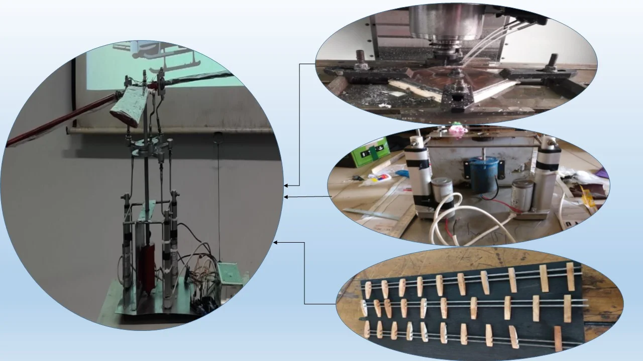
This study describes an integrated framework in which the basic elements of Aerospace Engineering (performance, aerodynamics and structure) and functional elements (suspension, visibility and production) are integrated and considered. In this study, a fully functional rotor system has been fabricated that can be used as one of the training resources for Aeronautical students. For making the rotor system, various parts of the system have been designed on Solidworks and complete mechanism has been simulated with ANSYS. System analysis has been done at various RPM's and Angles of Attack (AOA). In terms of merit the right items have been selected and processed to provide them with the right shape. In terms of the design and implementation, various machines such as gas welding, arc welding, CNC milling and radial machinery have been used. Certain parts such as electric motors, linear actuators and loading cells have been used. All the fabricated components and electric motor, actuator, load cells are then assembled. This rotor system can produce less lift due to high dead weight and low power motor and having some safety issues.
Highlights
- A fully functional rotor system has been designed and fabricated in this study.
- Solidworks is used as the main designing software to design different parts of the system and ANSYS is used for simulating the whole mechanism.
- System analysis is done at various RPM's and Angles of Attack (AOA).
- The analysis of this rotor system shows that it produces moderate amount of lift which can be increased by reducing dead weight and using more powerful motor.
1. Introduction
Rotor mechanism is the most vital mechanism for any helicopter. Rotor system as a whole helps the helicopter to take off, land and stay still in the air [1]. A helicopter main rotor or rotor system is the multitude of several rotary rotor blades and a control system that propagates the aerodynamic lift force that supports the weight of the helicopter, and the thrust that obviates aerodynamic drag in forward flight [2]. The helicopter rotor is powered by the engine, through the dispatch, to the rotating mast. In this experiment, we have focused on designing and building a fully functional basic rotor system of a helicopter [3, 4]. Firstly, we would like to mention some previous attempts at designing and analysis of a rotor system or parts of rotor system. Design analysis and fabrication of a helicopter main rotor system has been investigated in the following articles. Using ice protection system, Flemming et al. [5] investigated the helicopter rotor dynamics. Brown and William [6] studied experiments involving a microwave beam to power and position a helicopter. Scapinello [7], through composite materials applications investigated helicopter rotor used materials. Potter [8] applied an experimental study to identify improving reliability and eliminating maintenance with elastomeric dampers for rotor systems. In another work, Cohen et al. [9] studied a design study of a scale model bearingless helicopter rotor system using composite materials. Kim et al. [10] investigated modelling of the aerodynamics of coaxial helicopters–from an isolated rotor to a complete aircraft. Fulmer et al. [11] studied design of a helicopter hover test stand. Shin et al. [12] investigated design, manufacturing, and testing of an active twist rotor. In another investigation, David et al. [13] attempted to design helicopter rotor blades where optimization techniques had been used for placing natural frequencies. And in this case, both stiffness and mass distribution had been taken under consideration as the design problem. In another case, Stefan [14] analyzed a free flying helicopter with fully articulated rotor using Multi Body System (MBS). In Ref. [18], T. Charles et al. [15] designed and developed a collective pitch and cyclic pitch propeller (CPCPP) as a full scale working prototype for autonomous underwater vehicle (AUV) propulsion. In this paper our main objective is to find out and understand the functions of a rotor system practically and to motivate the students studying in this field of engineering. In this study, we undertake a much less aspiring target than the design of a complex rotor system or use different twist and turns to the rotor blades to find out the effects or use optimization techniques to minimize hub loads. Rather we focused on designing a basic rotor system taking some basic problems of rotor dynamics into consideration. Apart from the functionality, we have analyzed the mechanism of our rotor system through CFD. One of the main purposes of this experiment is to change the pitch and angle of attack of the blades together and find out the values of lift generated for those conditions respectively [16]. We have calculated the theoretical values and collected the practical values and established a comparison between them in this study. The limitations we faced in this study is that the lift produced by our rotor system was less due to high dead weight and less powerful motor. With better materials and more powerful motor the efficiency of the rotor system and the amount of lift produced by it can be developed significantly. The future scope for this study includes not only the improvement of the basic rotor system but to address it with different complexities and real life problems and also finding out and experiment with a more efficient design for hubs and rotor blades. This manuscript contains the full details about our design, modelling, simulation, final output and comparison between theoretical and practical values of generated lift.
2. Design and fabrication
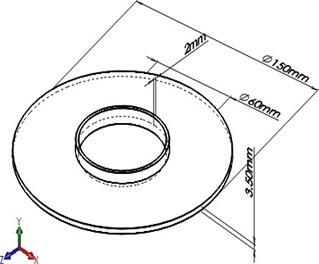
2.1. Upper swash plate
Special linkages attach the upper swash plate to the rotor shaft. The rotor shaft is rotated by the motor engine, which also rotates the upper swash plate and the rotor blade system. The system also includes blade grips, which connect the blades to a hub.
The structure of upper swash plate is fabricated using mild steel of 124.69 mm outer diameter and 88mm inner diameter along with 15mm depth. It required material turning, facing and sanding using lathe machine height. Weight factor has been kept under consideration.
Fig. 13D view of upper swash plate
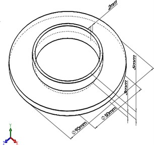
2.2. Lower swash plate
The rotating (upper) swashplate is attached to the stationary (lower) swashplate via a bearing and rotates with the main rotor mast. The lower swash plate is kept from rotating independently of the blades, which would add torque to the actuators, thanks to an anti-rotation link. An anti-rotation slider is usually present on the upper swashplate to prevent it from rotating. Both swashplates are considered a single entity.
The structure of lower swash plate is fabricated using mild steel of 150 mm outer diameter and 78 mm inner diameter and with a height of 15 mm. It required material turning, facing and sanding using lathe machine. Weight factor has been kept under consideration.
Fig. 2Fabrication process of lower swash plate
a)
b)
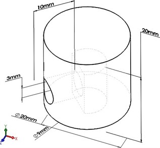
2.3. Shaft
A shaft is a rotating machine component with a circular cross section that is used to transfer power from one element to another, or from a machine that generates power to a machine that absorbs it. Many members, such as pulleys and gears, are fixed on it, on the other side. A hollow cylinder shaft is brought of 330 mm length and with a diameter of 18 mm. The material used is mild steel, and again weight factor has been kept under consideration
Fig. 33D view of shaft
2.4. Motor base
An electrical motor is a mechanism that converts electrical energy to mechanical energy. Most electric motors generate force in the form of shaft rotation by combining the magnetic field of the motor with electric current in a wire winding. Direct current (DC) sources, such as batteries, motor vehicles, or rectifiers, or alternating current (AC) sources, such as a power grid, inverters, or electrical generators, can power electric motors. Mechanically, an electric generator is similar to an electric motor, but it operates in the opposite direction, mechanical energy to electrical energy conversion motor bases are made of mild steel and serve as a motor's foundation. The motor base's construction is made from readily available materials. Mild steel with a length of 250 mm, a width of 180 mm, and a thickness of 3 mm. It necessitated the cutting, fitting, and welding of materials. The weight factor has been taken into account.
Fig. 43D view of motor base
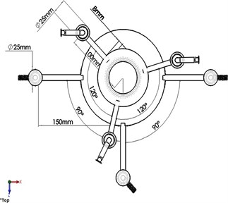
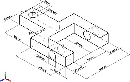
2.5. Articular joint
The articular joint construction is made of readily available mild steel. It necessitated the cutting and drilling of materials. It is made on a CNC computer. The weight factor has been taken into account.
Fig. 53D view of articular joint
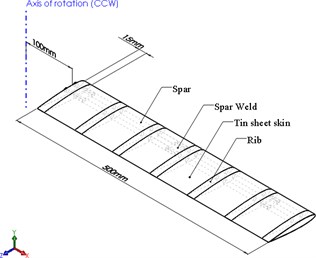
2.6. Rotor blade
The fuselage’s construction is made up of mild steel and wood. Material cutting, fitting, riveting, and welding were all necessary. The blade ribs are shaped like an airfoil, and the spars are made of I-section steel. With the aid of a rivet device, the whole frame is covered in aluminum sheet. The weight factor has also been taken into account.
Fig. 6a) Front view of blade, b) 3D view of blade
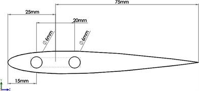
a)
b)
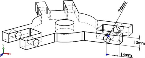
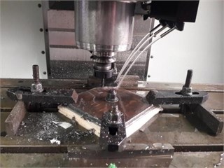
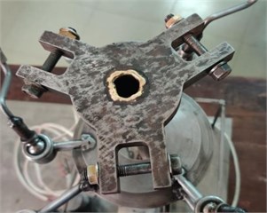
2.7. Rotor hub
The rotor hub’s structure is made of mild steel with a 70 mm diameter and three pairs of 35 mm tooth lengths, as well as a height of 17 mm. It necessitated material cutting, drilling, and fabrication in a CNC machine, as well as drilling with a drilling machine. The weight factor has been taken into account.
Fig. 7a) 3D view of rotor hub, b) fabrication process of rotor hub
a)
b)
c)
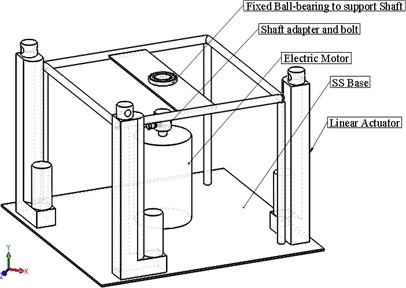
2.8. Final assembly
After accomplishing final assembly of all rotor components, the systems are inspected. Assuring safety and airworthy condition, the rotor was set for the following functions-
– To change pitch and angle of attack of blades together.
– To use it for demonstrating basic movements of the rotor blades.
– Forces generated due to various movement of the rotor blades are calculated.
– To measure the lift generated for different rpms and angle of attacks (AOA).
Fig. 8a) 3D view of final assembly, b) fabrication process of final assembly
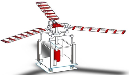
a)
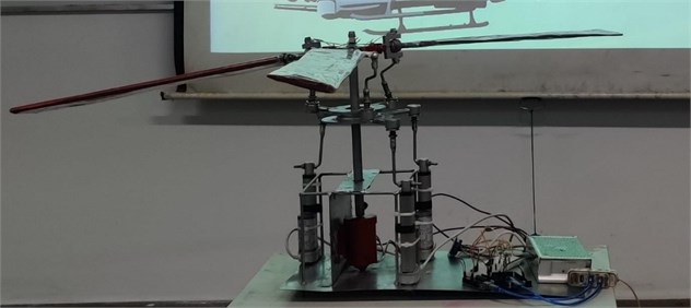
b)
3. Detail design
3.1. Airfoil selection
“NACA-0012” was selected as cross section of the blade because of its smooth curve of CL vs alpha and high stall angle and optimum thickness.
Fig. 9Airfoil NACA-0012
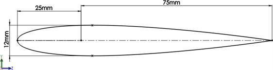
Chord length: 100 mm = 0.1 m.
Aerodynamic Chord: 25 % of chord = 25 mm.
Max /: 61.7 at 6.5° with Reynolds no. 500,000, Stall angle: 15° (approx.)
Fig. 10Charts of aerodynamic properties of NACA-0012 at Reynolds No. 500,000
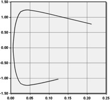
a) Cl v Cd
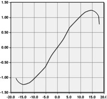
b) Cl v alpha
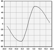
c) Cl/Cd v alpha
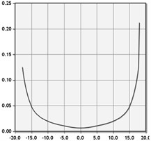
d) Cd v alpha
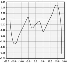
e) Cm v alpha
3.2. Blade sizing
The very first step of our design is to determine the dimension of the rotor blade of the rotor mechanism. This part is done by following various design approach of RC helicopter blades.
The primary assumption of the dimension for the blade is disc radius = Blade span = = 0.5 m.
Blade chord = = 0.1 m, = number of blades.
From blade elementary theory:
Solidity factor, .
Now, for 3 blade, 3, solidity factor, .
Again, for 2 blade, 2, solidity factor, .
Lift curve slope:
where, – first term in Fourier series = 2 /rad, – Oswald efficiency factor = 0.9, = aspect ratio = / = 0.5/0.1 = 5. So, lift curve slope:
Now, flapping frequency, ; where, – pitch angle of the blade varies from 0-12°.
Angular velocity for the rotor blade .
And blade tip velocity .
Coefficient of thrust .
Thrust, , where, density of air, 1.225 kg/m3, area – 0.7853981634 m2.
Coefficient of power .
Power , where, density of air, 1.225 kg/m3, area – 0.7853981634 m2.
4. CFD validation
Computational Fluid Dynamics (CFD) is an important technique that is widely used in mechanical engineering applications. Throughout the flow area, it includes machine solutions to the governing Navier-Stokes Equations. Because of the simpler flow models, the strategy allows for the simulation and analysis of complex problems without jeopardizing the integrity of the data. Helicopters and unmanned aerial vehicles (UAVs) require vertical takeoff and landing capabilities. In the case of propeller disc models and blade component theory, the current mathematical models used by Saab are trivial. Associate in Nursing research in system fluid dynamics (CFD) is performed on a chopper scale model, with a focus on the main-rotor blades, in this article. The main-rotor blades of the chopper model are encapsulated in a background area, and the flow field is solved using Ansys Fluent. When the Finite Volume methodology (FVM) was chosen as a discretization technique, a surface and volume mesh time was created that contained just over a pair of, 716,385 tetrahedral cells (binary), 476,881 nodes (binary). The cases of hover and forward were investigated. Hover flight cases were generated by varying the cumulative pitch angle (0) of all the blades. At the heavier-than-air craft free stream Mach number of 0.185, forward flight cases were done solely by adjusting the axis of rotation angle of attack (s) and thus the collective pitch angle (0), however, a cyclic pitch motion is not included. This study did not look into cyclic pitch motion. To summarize, using a simple rotating zone condition with stationary blades to investigate the main-rotor blades victimization CFD can operate with only minor differences from mathematical results. When overset meshes are applied to blades with a cyclic pitch motion (0, s area unit present), the roll and pitching moments are successfully removed from the results.
4.1. CAD modeling
SolidWorks was used to create the 3D blade of uniform cross section of Airfoil NACA-0012, and Ansys Design Modeler was used to create the domain. The model has three blades with a zero twist angle, as well as a collective and cyclic pitch management that can be changed using the inherently swash plate. A vertical stabilizer and rotor were also missing from the model.
Fig. 11a) Domain in PBC method, b) domain in cylindrical method.
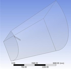
a)
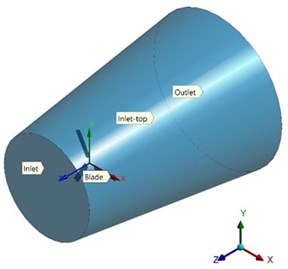
b)
Here, blade radius = = 0.5 m = 500 mm, inlet distance from blade = 2, outlet distance from blade = 6, inlet radius = 3.
Outlet radius = 5, periodic offset angle = 120°, rotation is about axis.
4.2. Meshing
Mean orthogonality should be greater than 0.15, and maximum skewness should be less than 0.95. Incorrect simulation results can be caused by bad cells or components. These are, however, general guidelines that are dependent on the physics solved or the location of the cells.
Table 1The quality of the mesh
Method | Mesh metrics | Min | Max | Avg | Standard deviation |
Periodic boundary condition | Skewness | 7.398e-006 | 0.9104 | 0.21911 | 0.12711 |
Orthogonal quality | 6.0798e-004 | 0.99974 | 0.85324 | 0.13333 | |
Aspect ratio | 1.1592 | 5329. | 80.541 | 349.02 | |
Cylindrical domain | Skewness | 1.3236e-004 | 0.89903 | 0.22963 | 0.12203 |
Orthogonal quality | 0.2231 | 0.99631 | 0.86024 | 8.5651e-002 | |
Aspect ratio | 1.1654 | 10.809 | 1.8407 | 0.46848 |
5. Discussions
Main results: Flight simulations in hover mode.
Calculations: Blade length = 500 mm, no of blades = 3.
Table 2Flight simulations in hover mode
in Radian | Lambda | RPM | Omega | Tip velocity | |||||||
5 | 0.0872 | 0.1909 | 4.349 | 0.0415 | 50 | 5.235 | 2.617 | 0.0069 | |||
Cp | Thrust | Power | Power in Hp | ||||||||
0.000286963 | 0.022770386 | 0.059612732 | 7.98029E-05 | ||||||||
CFD results.
Table 3Viscous model: Spalart-Allmaras (Eq. (1))
RPM | Tip velocity | Thrust on blade | Thrust on plane below blades (100 mm) | Torque | |
5 | 50 | 3.58 m/s | 0.0522478 [N] | 0.019456 [N] | 0.0079284 [N m] |
Table 4Viscous model: K-omega (Eq. (2))
RPM | Tip velocity (in standard frame) | Thrust on blade | Thrust on plane below blades (100 mm) | Torque | |
5 | 50 | 3.65 m/s | 0.0645128 [N] | 0.0248902 [N] | 0.00137146 [N m] |
Table 5Viscous model: K-epsilon (Eq. (2))
RPM | Tip velocity (in standard frame) | Thrust on blade | Thrust on plane below blades (100 mm) | Torque | |
5 | 50 | 3.16 m/s | 0.0535734 [N] | 0.020338 [N] | 0.0069038 [N m] |
In this study, we have a built a fully functional rotor system. Blade length of the rotor is 500 mm and no of blades is 3. There are two portions of our calculation. One is flight simulation in hover mode and the other is CFD results based on 3 viscous models. The values taken from the actual working rotor have been calculated here and a CFD calculation using 3 equations is also taken. For every case is 5° which is 0.0872 in Radian and RPM is 50.
In hover mode, is 0.000286963, tip velocity is 2.617 m/s, thrust is 0.022770386 N, power is 0.059612732 and power in HP is 7.98029E-05. These tip velocity, thrust and power are less than the CFD results.
Comparing the CFD results, it has been found that for 1 equation, tip velocity is 3.58 m/s which is less than the tip velocity of K-omega 2 equations and greater than K-epsilon 2 equations. Thrust for 1 equation is 0.0522478 N which is less than both 2 equations result. Torque calculated for 1 equation is 0.0079284 Nm which is greater than both 2 equations result.
For K-omega 2 equations, tip velocity is 3.65 m/s which is greater both 1 equation and K-epsilon 2 equations result. Thrust calculated is 0.0645128 N which is greater than both 1 equation and K-epsilon 2 equations result. Torque calculated is 0.00137146 Nm which is less than both the other cases.
For K-epsilon 2 equations, tip velocity is 3.16 m/s which is less than both 1 equation and K-omega 2 equations result. Thrust calculated is 0.0535734 N which is greater than 1 equation but less than K-omega 2 equations result. Torque calculated is 0.0069038 Nm which is less than 1 equation result but greater than K-omega 2 equations result. There were certain limitations in fabrication of the rotor mechanism.
As finalizing the design and understanding the blade momentum theory took much time, we had to fabricate the rotor mechanism in shortest possible time. Due to shortage of material availability we had to choose the material that was already prepared at the market. Due to lack of proper machinery like 3D printer we had to choose random cutting machine. The rotor blade performance would have been much better if the blade airfoil material was balsa wood instead of furniture wood. Due to lack of funding used motor was purchased for our fabrication. For further development of this project some improvements can be done.
Composite material can be used instead of mild still. Balsa wood can also be used for airfoil. To further increase the lift and overall performance a better motor and better battery can be used. Further development like tail rotor mechanism and other parts of a helicopter can also be built.
6. Conclusions
This paper presents designing and fabrication process of a basic helicopter rotor mechanism.
1) The process started with understanding the basic helicopter mechanism.
2) After understanding the basic theory, we started to learn about different joints and different mechanisms. Like the swash plate mechanism, blade mechanism, articular joint, hub mechanism.
3) We also studied about the different machining technique like CNC machining, lathe machining, uses of vice.
4) After understanding all those we started to design the whole machine.
5) We started to build small parts and after manufacturing all those parts we started to assemble it.
6) We studied both practical result and result we found through simulation and compared them in this study.
7) This study is basically for understanding the different joints that are used in rotor and the different motion that the helicopter blade used like flapping motion, pitch up or down motion and feathering motion.
References
-
J. D. Singleton and W. T. Yeager, “Important scaling parameters for testing model-scale helicopter rotors,” Journal of Aircraft, Vol. 37, No. 3, pp. 396–402, 2000, https://doi.org/10.2514/2.2639
-
K. Skiba, “Designing and FEM simulation of the helicopter rotor and hub,” IOP Conference Series: Materials Science and Engineering, Vol. 710, No. 1, 2019, https://doi.org/10.1088/1757-899X/710/1/012003
-
J. G. Leishman, “A history of helicopter flight,” University of Maryland, 2000, http://terpconnect.umd.edu/~leishman/Aero/history
-
T. Lee, I. Chopra, “Design of piezostack-driven trailing-edge flap actuator for helicopter rotors,” Smart Materials and Structures, Vol. 10, No. 1, 2001, https://doi.org/10.1088/0964-1726/10/1/302
-
R. J. Flemming and P. J. Alldridge, “Sikorsky S-92A® and S-76D™ Helicopter Rotor Ice Protection Systems,” No. 2007-01-3299. SAE Technical Paper, 2007, https://doi.org/10.4271/2007-01-3299
-
W. C. Brown, “Experiments involving a microwave beam to power and position a helicopter,” IEEE Transactions on Aerospace and Electronic Systems, Vol. 5, pp. 692–702, 1969, https://doi.org/10.1109/TAES.1969.309867
-
F. Scapinello, “Helicopter Composite Materials Applications: Rotors,” Wiley Encyclopedia of Composites, pp. 1–4, 2011, https://doi.org/10.1002/9781118097298.weoc105
-
J. L. Potter, “Improving reliability and eliminating maintenance with elastomeric dampers for rotor systems,” Journal of the American Helicopter Society, Vol. 18, No. 1, pp. 23–28, 1973, https://doi.org/10.4050/JAHS.18.1.23
-
Cohen and Gary, “A Design Study of a Scale Model Bearingless Helicopter Rotor System Using Composite Materials,” Dissertation, http://hdl.handle.net/10539/22844
-
H. W. Kim and R. E. Brown, “Modelling the aerodynamics of coaxial helicopters–from an isolated rotor to a complete aircraft,” EKC2008 Proceedings of the EU-Korea Conference on Science and Technology, Springer, Berlin, Heidelberg, Vol. 124, pp. 45–59, 2008, https://doi.org/10.1007/978-3-540-85190-5_4
-
J. C. Fulmer, J. P. Labrie, and B. E. Axelsson, “Design of a Helicopter Hover Test Stand,” 2015, https://digital.wpi.edu/show/3r074w47j
-
Shin and SangJoon, “Design, Manufacturing, and Testing of an Active Twist Rotor,” Dissertation Massachusetts Institute of Technology, 1999, http://hdl.handle.net/1721.1/49684
-
D. A. Peters, M. P. Rossow, A. Korn, and T. Ko, “Design of helicopter rotor blades for optimum dynamic chracteristics,” Computers and Mathematics with Applications, Vol. 12, No. 1, pp. 85–109, 1986, https://doi.org/10.1016/0898-1221(86)90089-1
-
S. Waitz, “MBS Analysis of a Free Flying Helicopter with Fully Articulated Rotor,” 2014, http://hdl.handle.net/20.500.11881/3484
-
T. C. Humphrey, “Design and Fabrication of a Collective and cyclic pitch propeller,” Memorial University of Newfoundland, 2005, http://research.library.mun.ca/id/eprint/10706
-
D. S. Jenney, “Rotor Technology for New Generation Helicopters,” No. 751106, SAE Technical Paper, 1975, https://doi.org/10.4271/751106
About this article

