Abstract
The grinding process is commonly used as the final stage of processing. It is used to produce elements that require more tolerance and smooth surface. Considering other processing, such as turning or milling, grinding requires very high energy input per unit volume of material removal. A significant proportion of this energy in the process turns into heat in the grinding zone, which leads to increased temperature. This paper describes and compares two methods of temperature measurement in the cutting zone during surface grinding. The study aimed to determine the differences in the results of temperature measurements using an indirect method, using an analysis of thermal images, and a direct method, using a thermocouple. Two different sets of measurement apparatus were used in the experiment: a thermal imaging camera and a thermocouple with appropriately selected software. The factors affecting the errors obtained with each of the above measurement methods are discussed and the resulting differences in the results are discussed.
1. Introduction
In recent years, there have been intensive developments in the use of abrasive machining in the manufacturing processes of machine parts. Particular emphasis has been placed on manufacturing technology. One of the most important directions of development is the increasingly intensive automation of production.
Abrasive machining (as one of the metal cutting processes) still retains an essential position. It results, among other things, from the necessity to ensure the appropriate shape and dimensional accuracy of products and the quality of their surface.
Together with the increase in the share of abrasive machining in manufacturing processes, there has been an increase in the requirements placed on both the construction materials and the products manufactured during this machining. Surface quality, object durability, production efficiency and effectiveness - these are only some of the requirements set for modern products and processes [1, 2]. Therefore, there is a need to deepen the knowledge, among other things, of the grinding process.
The improvement of metal cutting processes requires, among other things, the most accurate possible knowledge of the physical phenomena occurring in these processes. These phenomena are various, e.g.: thermal, chemical, mechanical. They occur in the workpiece material as well as in the tool - in the case of grinding in a grinding wheel.
Therefore, one of the most important phenomena that affect the quality of workpieces is the heat generated in the machining zone, which can be associated with the temperature distribution in this zone [2-4].
In the grinding process, the temperature determines the condition of the surface layer, particularly in the area of contact between the grinding wheel and the workpiece. When the workpiece is in contact with the grinding wheel, some factors occur which are unfavorable to the wheel, e.g., abrasive wear, toughness wear, etc. [5-8].
High temperatures can greatly intensify this process [9, 10]. Therefore, determining the energy involved in the machining process in the cutting zone plays an essential role [11, 12]. During the grinding process, elastic-plastic deformation occurs in the workpiece material due to a rise in temperature in the contact zone between the workpiece and the grinding wheel. If the amount of heat in the cutting zone is too high, grinding burns can occur on the surface of the workpiece. The result is, among other things, a deterioration of the properties of the surface layer of the workpiece, including its structure [13-15]. The effects of grinding burns include: changes in hardness, the formation of residual stresses and microcracks in the surface layer, thermal and structural deformation of the workpiece [16, 17]. They occur even when no physical defect is observed. Wang et al. evaluated that accurate measurement of grinding zone temperature enables thermal damage reduction and control in the grinding process [18]. Baumgart et al. presented factors influencing the formation of grinder burns which are investigated by continuous temperature measurement [19, 20]. Various technologies have been developed to measure temperature, chief among them thermocouples and infrared measurement techniques.
To reduce the possibility of undesirable changes in the structure of the surface layer of the workpiece material and the layers located deeper, appropriate methods are used to lower the working temperature at the contact between the grinding wheel and the workpiece material [21], [22-24]. In most cases, a coolant is used which, in addition to lowering the temperature, assists in removing chips from the grinding area. Damasceno et al. conducted a study to evaluate the performance of various coolant techniques [25].
Unfortunately, in the grinding process, the efficiency of heat removal from the grinding zone is still not sufficient. As a result, the probability of the occurrence of grinding burns and other adverse effects associated with excessive temperature in the grinding zone is still high [26-28].
Another important phenomenon that occurs during the grinding process is swarf infiltration on the active surface of the wheel. This process may cause inhomogeneities on the surface of the workpiece material and influence the deterioration of the cutting ability of the grinding wheel, what results in its faster wear. Therefore, it is necessary to control the grinding wheel operation, especially when grinding internal cylindrical surfaces [29].
The current literature has mainly focused on the functional relationships between many parameters of the grinding process to understand the physical phenomena taking place [20, 30-34]. There are carried out experimental studies to study adverse phenomena, which may lead to the effective elimination of errors and effects of wrong conducting grinding process. However, an important issue is the technique of temperature measurement [35-38]. Of the many existing temperature measurement methods, only a few found have been applied to the grinding process. It is possible to divide them into:
1. Methods based on the principle of thermoelectric power measurement:
– foreign element method,
– half-foreign element method,
– natural element method.
2. Methods based on other principles:
– thermo inks method,
– photoelectrical methods (pyrometers).
One of the modern methods of measuring temperature is the thermal imaging method. It is a temperature measurement using a thermal imaging camera. Two applications of this method can be presented:
1. Temperature measurement of plains;
2. Temperature measurement of cylindrical surface, external and internal.
Thermal imaging cameras are mainly used for qualitative measurements (e.g., identification of points in technical or medical diagnostics, search for thermal bridges in energy efficiency studies of buildings), increasingly for quantitative measurements where precise absolute values of temperature are required [39-41].
In this article, an experimental study will be conducted to determine the amount and type of energy delivered to the workpiece during the surface grinding process. Malkin et al. performed a study in which as much as 85 % of the thermal energy is transferred to the workpiece in the grinding process [20]. For this purpose, temperature measurements in the contact area between the workpiece and the grinding wheel will be used. These measurements, taking into account variations in the individual machining parameters, will be used to estimate precisely that portion of the energy that is transferred from the grinding wheel to the workpiece.
2. Research plan on the temperature in grinding process
The planning of a selected experiment occurs when the implementer has decided on a technical object and a set of values to characterize that object. The set of values includes: variable, fixed, input, and output values. It is usually assumed that these quantities will take on specific values expressed by a number and a unit of measure, e.g., a physical, chemical, or technical quantity. It is important to define these parameters correctly, since this has an impact on the possible errors that may occur during the execution of the experimental plan. Therefore, the input values are important qualities that are part of the characteristics of the experimental plan. Assuming closed input values , where , one should always take into account the technical feasibility of the research, in particular:
– proper functioning of the assumed test object in the assumed range of input values - this is a prerequisite for the planned experiment,
– proper functioning of the assumed object of research at certain even limit (maximal-minimal) values - this is a sufficient condition, only supplementing the appropriately selected initial values.
Selection of an appropriate experimental research plan depends on its specificity and objective. It was assumed that research will be carried out for two input sizes: depth of cut ap and feed f. By providing nonlinear functional dependencies between the output size and independent variable, the appropriate values of input size were adopted. They were differentiated depending on the grinded material. Parameters adopted for C45 steel and for Mo63 brass were presented in Table 1.
Table 1Input parameters adopted for Mo63 brass and C45 steel
C45 steel | Mo63 brass | ||
[mm] | [mm] | [mm/min] | [mm/min] |
0.1 | 0.1 | 100 | 60 |
0.2 | 0.2 | 100 | 60 |
0.05 | 0.3 | 100 | 60 |
0.05 | 0.3 | 60 | 100 |
0.1 | 0.2 | 60 | 100 |
0.2 | 0.1 | 60 | 100 |
Adoption of variable feed rate f required pre-screening studies to suggest the most appropriate feed rate. The final number of research points in the complete experiment plan was (Table 2).
Table 2Summary of the number of level values of input factors: grinding depth (ap) and feed (f), as well as the number of research points according to the complete plan
No | Number of levels | Number of levels f | Material | Necessary number of research points |
1 | 3 | 2 | C45 steel | |
2 | 3 | 2 | Mo63 Brass |
3. Temperature measurement
In monitoring the temperature change of a grinded workpiece, it is essential to be aware of the dependence of the magnitude of the detected radiation signal. Fig. 1 presents a scheme of the most important elements on the temperature measurement stand in grinding process of plains on the CNC surface grinder. Abrasive tool with determined cutting speed and specified feed , moving with the feed rate , launching the cutting process of processed material.
Fig. 1Scheme of the stand for temperature measurement with thermal imaging camera
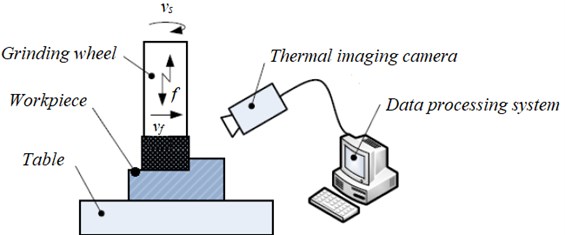
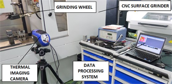
Fig. 2 shows the real view of the stand. Visible, a thermal imaging camera is connected with wires to the computer. The data processing system software installed on the computer is used for acquisition and data analysis sent online with a thermal imaging camera on a laptop computer, located on the top of a tool cupboard.
Fig. 2Real view of the stand while performing tests
Selected, the most relevant information on experimental conditions was presented in Table 3. It includes among others information: on grinding wheel, machine tool, grinded workpiece and measuring systems.
Table 3Basic information on the elements of the test stand
Object | Description |
Machine tool | CNC Surface Grinder from Giebel & Hotz GmbH: FS 640 with SINUMERIK 840D control system from SIMENS |
Tool | Grinding wheel of hardness H, grain size 60 and structure 8 |
Workpiece | Cubes with Mo63 brass and C45 steel |
Temperature sensor | Thermocouple of type K (NiCr-Ni) |
Temperature measuring instrument | Multimeter PC 500a, SANWA PC 500A MULTIMETER, DIG, HAND GELD, 4 DIGITS |
Detector | System of thermographical devices FLIR SC500 |
Data processing system | ASUS Laptop with image recording system ALTAIR SYSTEMS |
Coolant | No coollant |
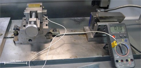
In this study, both a thermal imaging camera and a system of direct temperature measurement were used. This system consist of thermocouple and a relevant digital multimeter (Fig. 3). Two different measuring instruments were used, due to the need to verify indirect measurements, conducted using a thermal imaging camera and measurements using a standard thermocouple.
Fig. 3Digital multimeter with connected thermocouple (the tip of thermocouple placed in the outlet hole of the workpiece at a distance from 0 up to 3 mm from the grinded surface)
In the further stage, the type of processed material was determined (Mo63 brass and steel C45) as well as the cutting parameters were defined, for which were supposed to be performed measurements, i.e. (Table 4; Table 5):
a) Depth of cut (),
b) Width of cut (),
c) Feed (),
d) Cutting speed (),
e) Thermocouple distance from the beginning of hole (),
f) Emission ().
Following the guidance in the second section for planning the experiment and the knowledge of cavity machining technology for C45 steel and Mo63 brass, 3 levels of factor (3 values of variables), and 2 levels of factor (2 values of variables) were adopted. The adoption of a range of variable feed rate f required pre-screening studies to suggest the most appropriate feed rate. The parameters ( and for all measurements take the same value and are respectively: 40 mm, 21 m/min). They were also chosen on the basis of pre-screening studies. These values were verified in a SINUMERIK 840 D control system. The thermocouple distance from the beginning of hole was measured using a digital caliper. The emissivity values e for both materials were read for each individual material from a table provided by the manufacturer of the thermal imaging camera and ALTAIR software.
Table 4Parameters of cutting adopted for C45 steel
[mm] | [mm] | [mm/min] | [m/min] | [mm] | [–] |
0.1 | 40 | 60 | 21 | 2.6 | 1 |
0.2 | 40 | 60 | 21 | 2.5 | 1 |
0.05 | 40 | 60 | 21 | 2.3 | 1 |
0.05 | 40 | 100 | 21 | 2.25 | 1 |
0.1 | 40 | 100 | 21 | 2.2 | 1 |
0.2 | 40 | 100 | 21 | 2.0 | 1 |
Table 5Parameters of cutting adopted for Mo63 brass
[mm] | [mm] | [mm/min] | [m/min] | [mm] | [–] |
0.1 | 40 | 100 | 21 | 1 | 0.6 |
0.2 | 40 | 100 | 21 | 0 | 0.6 |
0.3 | 40 | 100 | 21 | 0.8 | 0.6 |
0.2 | 40 | 60 | 21 | 0.5 | 0.6 |
0.1 | 40 | 60 | 21 | 0.3 | 0.6 |
0.2 | 40 | 60 | 21 | 0.2 | 0.6 |
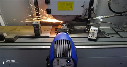
Images of infrared temperature distributions were obtained using a thermal imaging camera, which next have been transferred to the data processing system for further analysis. In the case of digital multimeter, which was connected with thermocouple, we obtained direct temperature values (Fig. 4).
Fig. 4Implementation of the cutting process
4. Analysis of the grinding temperature measurement results
12 videos were recorded in studies with a thermal imaging camera (6 videos for C45 steel and 6 videos for Mo63 brass) depending on assumed input values: depth of cut and feed . These images were directly recorded in the window of ALTAIR program (Figs. 5 and 6), from which the highest registered temperature was indicated.
Fig. 5Registered images with thermal imaging camera FLIR SC5000 indicate maximum temperature values for C45 steel, resulting in the grinding process. The images a) to f) refer to the parameters given in Table 6
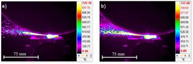
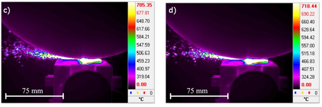
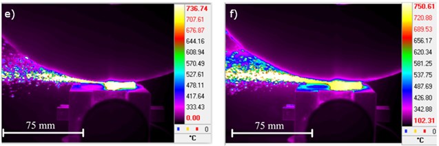
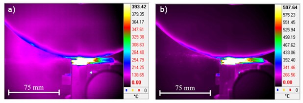
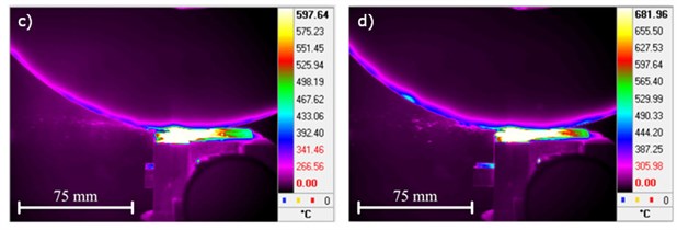
Fig. 6Registered images with thermal imaging camera FLIR SC5000 indicate maximum temperature values for Mo63 brass, resulting in the grinding process. The images a) to f) refer to the parameters given in Table 7
The resulting values observed in the grinding process were:
– – the highest recorded temperature with thermal imaging camera [℃],
– – the highest recorded temperature with thermocouple [℃].
In the following, tables (Table 6 and Table 7) with blue color indicated input parameters, for which the maximum temperature values were obtained. Red color indicates all obtained results using a thermal imaging camera and thermocouple , in addition red thickened values indicate the maximum obtained values for the indicated input parameters.
Table 6Initial and resulting values for C45 steel
Fig. | [mm] | [mm/min] | [mm] | [–] | [°C] | [°C] |
5(a) | 0.1 | 60 | 2.6 | 1 | 725 | 451 |
5(b) | 0.2 | 60 | 2.5 | 1 | 738 | 690 |
5(c) | 0.05 | 60 | 2.3 | 1 | 705 | 410 |
5(d) | 0.05 | 100 | 2.25 | 1 | 720 | 420 |
5(e) | 0.1 | 100 | 2.2 | 1 | 737 | 538 |
5(f) | 0.2 | 100 | 2.0 | 1 | 751 | 648 |
The initial stage of the substantive analysis is indication of the maximum temperature values obtained using a thermal imaging camera and thermocouple. Table 7 shows the highest temperature values for Mo63 brass, determined on the basis of received infrared images. It is possible to notice that the maximum temperature obtained using a thermal imaging camera is 682 ℃ for the depth of cut 0.3 mm and feed 60 mm/min. At the same value of the depth of cut and feed, the highest temperature was obtained with a digital multimeter, which was connected to thermocouple – its value taken was 418 ℃ (Table 7).
Table 7Initial and resulting values for Mo63 brass
Fig. | [mm] | [mm/min] | [mm] | [–] | [°C] | [°C] |
6(a) | 0.1 | 100 | 1 | 0.6 | 393 | 242 |
6(b) | 0.2 | 100 | 0 | 0.6 | 598 | 380 |
6(c) | 0.3 | 100 | 0.8 | 0.6 | 666 | 309 |
6(d) | 0.2 | 60 | 0.5 | 0.6 | 682 | 418 |
6(e) | 0.1 | 60 | 0.3 | 0.6 | 619 | 410 |
6(f) | 0.2 | 60 | 0.2 | 0.6 | 518 | 360 |
It follows that (in case of Mo63 brass) all large depths of cut and feed , the greater temperature of the workpiece. Referring to the results obtained for C45 steel (Table 6), it is possible to notice that the maximum values aren’t equal to the same values of the depth of cut and feed . Temperature 751 ℃ is a result received with a thermal imaging camera, where the initial parameters were the values 0.2 mm, 100 mm/min, ± 690 ℃ is a temperature shown using a digital multimeter connected to thermocouple (where 0.2 mm, 60 mm/min). It is clear that the maximum values differ in only one parameter, i.e., feed rate motion.
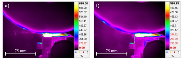
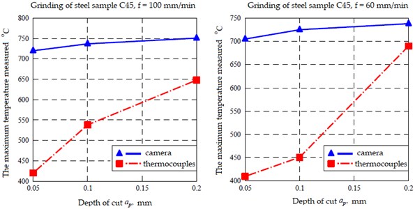
Linear temperature process measured with thermocouple indicates lower values compared to values on the graph (measured with a thermal imaging camera). These results clearly show different values both for cutting speed 100 mm/min and 60 mm/min – Figs. 7 and 8.
Fig. 7Graphs of temperature dependence (results obtained with thermal imaging camera Tk (blue color) and thermocouples Tp (red color) at cutting depth ap). Measurements were performed on Mo63 brass
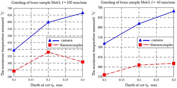
Fig. 8Graphs of temperature dependence (results obtained with thermal imaging camera Tk (blue color) and thermocouples Tp (red color) at cutting depth ap). Measurements were performed on C45 steel
5. Conclusions
Summing up the analysis of the results obtained with a thermal imaging camera and recorder connected to thermocouple, it is possible to notice that the most accurate measurement method is the analysis of infrared images. The advantage of this method of the instrument for temperature measurement is that you can register the entire cutting process and select the highest and lowest temperature value or other interesting us range. Using the thermocouple is also an effective way for temperature measurement; however obtained values in studies can always be subject to higher errors than those obtained using a thermal imaging camera. Undoubtedly, one of factors that affect results of measurements is distance of the thermocouple tip from the surface of workpiece. Referring to the results obtained for steel C45, it can be seen that the maximum values are not the same for the same values of depth of cut ap and feed rate . The thermocouple distance from the beginning of hole may be a factor that influenced the different temperature values. These distances may be too large for this type of workpiece material. These differences are also seen for Mo63 brass but are not as significant as for C45 steel. Further work on the temperature variation requires the creation and verification of appropriate mathematical models that would describe, at least in an approximate way, the thermal phenomena in the grinding process. Another factor that affects the results of research is the error resulting from the time of image registration with a thermal imaging camera. Videos generated in studies were recorded with time delay, which could result in lower temperature values recorded on the video than in real time. While recording images, the grinding wheel rotates with a rotational motion, which causes – in each return – rubbing of the cutting surface with different temperature of the grinding wheel. Hence, it results that it is a factor depending on the apparatus. Referring to the results obtained with a thermal imaging camera, it is possible to notice that the maximum temperature value, obtained while pulling out the tool from the workpiece, coincides with the maximum values recorded during all measurements performed with the adoption of all values of the cutting parameters. The conducted experiments have shown that the position of the thermocouple in relation to the ground surface plays an important role in thermocouple measurements. The positioning of the thermocouple with the dimensions of the sample changing during grinding is problematic. This results from the accumulation of heat loads during the grinding process. Thermography method gives a very reliable measure with many advantages for grinding. Most of these advantages compared with thermocouples offer a better resolution (spatially and temporally) and a whole window of values instead of only one with a thermocouple.
References
-
K. Wegener, F. Bleicher, P. Krajnik, H.-W. Hoffmeister, and C. Brecher, “Recent developments in grinding machines,” CIRP Annals, Vol. 66, No. 2, pp. 779–802, 2017, https://doi.org/10.1016/j.cirp.2017.05.006
-
P. V. Vinay and C. Srinivasa Rao, “Temperature assessment in surface grinding of tool steels,” Journal of Mechanical Science and Technology, Vol. 29, No. 11, pp. 4923–4932, Nov. 2015, https://doi.org/10.1007/s12206-015-1040-y
-
H. N. Li and D. Axinte, “On a stochastically grain-discretised model for 2D/3D temperature mapping prediction in grinding,” International Journal of Machine Tools and Manufacture, Vol. 116, pp. 60–76, May 2017, https://doi.org/10.1016/j.ijmachtools.2017.01.004
-
S. Malkin and R. B. Anderson, “Thermal aspects of grinding: Part 1 – Energy Partition,” Journal of Engineering for Industry, Vol. 96, No. 4, pp. 1177–1183, Nov. 1974, https://doi.org/10.1115/1.3438492
-
S. Santa-Aho, et al., “Development of Barkhausen noise calibration blocks for reliable grinding burn detection,” Journal of Materials Processing Technology, Vol. 212, No. 2, pp. 408–416, Feb. 2012, https://doi.org/10.1016/j.jmatprotec.2011.10.003
-
B. He, C. Wei, S. Ding, and Z. Shi, “A survey of methods for detecting metallic grinding burn,” Measurement, Vol. 134, pp. 426–439, Feb. 2019, https://doi.org/10.1016/j.measurement.2018.10.093
-
L. Li and F. Jiecai, “Research on mathematical model of grinding force,” Chinese Journal of Mechanical Engineering, Vol. 17, No. 4, pp. 31–41, 1981.
-
R. L. Hecker, S. Y. Liang, X. J. Wu, P. Xia, and D. G. W. Jin, “Grinding force and power modeling based on chip thickness analysis,” The International Journal of Advanced Manufacturing Technology, Vol. 33, No. 5–6, pp. 449–459, Apr. 2006, https://doi.org/10.1007/s00170-006-0473-y
-
A. Lefebvre, P. Vieville, P. Lipinski, and C. Lescalier, “Numerical analysis of grinding temperature measurement by the foil/workpiece thermocouple method,” International Journal of Machine Tools and Manufacture, Vol. 46, No. 14, pp. 1716–1726, Nov. 2006, https://doi.org/10.1016/j.ijmachtools.2005.12.009
-
D. Anderson, A. Warkentin, and R. Bauer, “Experimental validation of numerical thermal models for dry grinding,” Journal of Materials Processing Technology, Vol. 204, No. 1–3, pp. 269–278, Aug. 2008, https://doi.org/10.1016/j.jmatprotec.2007.11.080
-
V. Singh, P. Venkateswara Rao, and S. Ghosh, “Development of specific grinding energy model,” International Journal of Machine Tools and Manufacture, Vol. 60, pp. 1–13, Sep. 2012, https://doi.org/10.1016/j.ijmachtools.2011.11.003
-
L. de Martini Fernandes, et al., “Thermal model for surface grinding application,” The International Journal of Advanced Manufacturing Technology, Vol. 104, No. 5–8, pp. 2783–2793, Jul. 2019, https://doi.org/10.1007/s00170-019-04101-6
-
B. Lavisse, et al., “The effects of the flow rate and speed of lubricoolant jets on heat transfer in the contact zone when grinding a nitrided steel,” Journal of Manufacturing Processes, Vol. 35, pp. 233–243, Oct. 2018, https://doi.org/10.1016/j.jmapro.2018.07.029
-
P. Li, et al., “Effects of local strain rate and temperature on the workpiece subsurface damage in grinding of optical glass,” International Journal of Mechanical Sciences, Vol. 182, p. 105737, Sep. 2020, https://doi.org/10.1016/j.ijmecsci.2020.105737
-
Y. Shao, O. Fergani, B. Li, and S. Y. Liang, “Residual stress modeling in minimum quantity lubrication grinding,” The International Journal of Advanced Manufacturing Technology, Vol. 83, No. 5–8, pp. 743–751, Jul. 2016, https://doi.org/10.1007/s00170-015-7527-y
-
J. A. Badger and A. Torrance, “Burn awarness,” Cutting Tool Engineering, Vol. 52, No. 12, 2000.
-
B. W. Rowe, D. F. McCormack, and T. Jin, “Controlling the surface integrity of ground components,” Abrasives, pp. 24–30, 2001.
-
Y. Wang, C. Li, B. Li, M. Yang, and X. Zhang, “Advances and recent patents in the field of grinding temperature measurement methods,” Recent Patents on Materials Science, Vol. 8, No. 1, pp. 55–68, Mar. 2015, https://doi.org/10.2174/1874464808666150304233653
-
C. Baumgart, V. Heizer, and K. Wegener, “In-process workpiece based temperature measurement in cylindrical grinding,” Procedia CIRP, Vol. 77, pp. 42–45, 2018, https://doi.org/10.1016/j.procir.2018.08.206
-
S. Malkin and C. Guo, “Thermal analysis of grinding,” CIRP Annals, Vol. 56, No. 2, pp. 760–782, 2007, https://doi.org/10.1016/j.cirp.2007.10.005
-
C. Heinzel and B. Kolkwitz, “The Impact of fluid supply on energy efficiency and process performance in grinding,” CIRP Annals, Vol. 68, No. 1, pp. 337–340, 2019, https://doi.org/10.1016/j.cirp.2019.03.023
-
R. A. Irani, R. J. Bauer, and A. Warkentin, “A review of cutting fluid application in the grinding process,” International Journal of Machine Tools and Manufacture, Vol. 45, No. 15, pp. 1696–1705, Dec. 2005, https://doi.org/10.1016/j.ijmachtools.2005.03.006
-
C. Heinzel, D. Meyer, B. Kolkwitz, and J. Eckebrecht, “Advanced approach for a demand-oriented fluid supply in grinding,” CIRP Annals, Vol. 64, No. 1, pp. 333–336, 2015, https://doi.org/10.1016/j.cirp.2015.04.009
-
J. C. Aurich and B. Kirsch, “Improved coolant supply through slotted grinding wheel,” CIRP Annals, Vol. 62, No. 1, pp. 363–366, 2013, https://doi.org/10.1016/j.cirp.2013.03.071
-
R. F. Damasceno et al., “Performance evaluation of various cooling-lubrication techniques in grinding of hardened AISI 4340 steel with vitrified bonded CBN wheel,” The International Journal of Advanced Manufacturing Technology, Vol. 92, No. 9–12, pp. 3795–3806, May 2017, https://doi.org/10.1007/s00170-017-0434-7
-
M. W. Seidel, A. Zösch, and K. Härtel, “Grinding burn inspection,” Forschung im Ingenieurwesen, Vol. 82, No. 3, pp. 253–259, Mar. 2018, https://doi.org/10.1007/s10010-018-0270-4
-
C. Reser and C. Reich, “Grinding burn prediction with artificial neural networks based on grinding parameters,” in Smart SysTech 2019, European Conference on Smart Objects, Systems and Technologies, pp. 56–60, 2019.
-
F. Del Re, M. Dix, and F. Tagliaferri, “Grinding burn on hardened steel: characterization of onset mechanisms by design of experiments,” The International Journal of Advanced Manufacturing Technology, Vol. 101, No. 9–12, pp. 2889–2905, 2019, https://doi.org/10.1007/s00170-018-3156-6
-
S. Malkin and C. Guo, “Grinding Technology: theory & application of machining with abrasives,” 2nd Industrial Press Inc, 2008.
-
H. K. Tönshoff, T. Friemuth, and J. C. Becker, “Process monitoring in grinding,” CIRP Annals, Vol. 51, No. 2, pp. 551–571, 2002, https://doi.org/10.1016/s0007-8506(07)61700-4
-
P. R. de Aguiar, F. R. L. Dotto, and E. C. Bianchi, “Study of thresholds to burning in surface grinding process,” Journal of the Brazilian Society of Mechanical Sciences and Engineering, Vol. 27, No. 2, Jun. 2005, https://doi.org/10.1590/s1678-58782005000200007
-
P. Moulik, H. T. Yang, and S. Chandrasekar, “Simulation of thermal stresses due to grinding,” International Journal of Mechanical Sciences, Vol. 43, No. 3, pp. 831–851, Dec. 2001, https://doi.org/10.1016/s0020-7403(00)00027-8
-
H. Hamdi, H. Zahouani, and J.-M. Bergheau, “Modélisation par éléments finis des contraintes résiduelles induites par la rectification,” in 4th International Conference on Integrated Design and Manufacturing in Mechanical Engineering (IDMME 2002), 2002.
-
A. D. L. Batako, M. N. Morgan, and B. W. Rowe, “High efficiency deep grinding with very high removal rates,” The International Journal of Advanced Manufacturing Technology, Vol. 66, No. 9–12, pp. 1367–1377, 2013, https://doi.org/10.1007/s00170-012-4414-7
-
D. Perić, B. Livada, M. Perić, and S. Vujić, “Thermal imager range: predictions, expectations, and reality,” Sensors, Vol. 19, No. 15, p. 3313, Jul. 2019, https://doi.org/10.3390/s19153313
-
A. Brosse, P. Naisson, H. Hamdi, and J. M. Bergheau, “Temperature measurement and heat flux characterization in grinding using thermography,” Journal of Materials Processing Technology, Vol. 201, No. 1–3, pp. 590–595, May 2008, https://doi.org/10.1016/j.jmatprotec.2007.11.267
-
B. W. Rowe, “Principles of Modern Grinding Technology,” 2014.
-
X. Xu and S. Malkin, “Comparison of methods to measure grinding temperatures,” Journal of Manufacturing Science and Engineering, Vol. 123, No. 2, pp. 191–195, May 2001, https://doi.org/10.1115/1.1369358
-
T.-C. Su, “Assessment of cracking widths in a concrete wall based on TIR radiances of cracking,” Sensors, Vol. 20, No. 17, p. 4980, Sep. 2020, https://doi.org/10.3390/s20174980
-
A. Quattrocchi, F. Freni, and R. Montanini, “Self-heat generation of embedded piezoceramic patches used for fabrication of smart materials,” Sensors and Actuators A: Physical, Vol. 280, pp. 513–520, Sep. 2018, https://doi.org/10.1016/j.sna.2018.08.022
-
M. Ö. Korukçu and M. Kilic, “The usage of IR thermography for the temperature measurements inside an automobile cabin,” International Communications in Heat and Mass Transfer, Vol. 36, No. 8, pp. 872–877, Oct. 2009, https://doi.org/10.1016/j.icheatmasstransfer.2009.04.010
About this article

