Abstract
Not only has the dynamic stiffness of a rubber air spring been inherited by effects of the compressed air, but it has also been affected by hysteresis behaviors caused by the friction, viscoelasticity of bellow material. Hence, this paper will analyze comprehensively the stiffness model of a commercial rubber air spring. One of the first works is to predict the structure parameters including effective area, volume and their change rate. Then, the restoring force generated by compressed air will be analyzed and built through the theory of thermodynamics. The hysteresis model of the rubber bellow will be obtained based on the Berg’s frictional model connecting in parallel with fractional Kelvin-Voigt model. Next, an experimental apparatus is set up to identify the parameters of this model as well as evaluate the proposed restoring force model of the rubber air spring. The study results show that the analysis model of the rubber air spring matches well the measured data. This work will offer a helpful insight in the design of the vibration isolation system using rubber air springs as elastic elements.
1. Introduction
As known, mechanical springs including coil spring [1-3], Euler column spring [4-6] have been widely employed in the vibration isolation systems to suppress the unwanted vibrations transmitted from source to the isolated object. However, the isolation effectiveness of isolators using mechanical springs is limited because the spring coefficient is fixed. Besides, magnetic springs have been studied and applied widely in vibration isolation systems [7-8]. Due to controllable stiffness, the isolation performance of the magnetic spring isolator can be improved. But the drawback of magnetic spring is that only when it has low load. Accordingly, application limitation of the magnetic spring is inevitable.
Another type of elastic elements, which can overcome problems mentioned above, is air spring due to easy control of the spring coefficient and high bearing capacity. Thus, in recent years, this type has been applied widely in vehicle suspension field [9-11], vibration isolation platform [12] etc. A deep understanding of rubber air spring has been attracted by many scholars, engineers and scientists. Quaglia et al. [13] presented a thermodynamic model of an air suspension and a design procedure for a pneumatic suspension. Lee et al. [14] analyzed the stiffness model of an air spring, revealing the effect of the volume variation, the heat transfer and the effective area on the stiffness curve. Liu et al. [15] studied a dynamic stiffness and equivalent damping model of an air spring connecting with an orifice and an auxiliary reservoir, showing that the equivalent damping is increased according to reduction in the orifice area and excitation frequency. Zargar et al. [16] developed and experimentally evaluated a nonlinear mathematical model of an air spring, showing an effective prediction of the behavior of air spring. Finite Element Analysis has used to determine the nonlinear load-displacement curve of a rubber bumper used in air spring as well as the transmissibility and sensitivity [17]. The dynamic model of air spring for reducing the vibration transmissibility was developed and experimented by Gavriloski et al. [18]. The vertical stiffness of a rolling lobe air spring was analyzed and successfully experimented by Li et al. [19]. Moheyeldein et al. [20] studied the performance indices of an air suspension. Furthermore, Berg [21-22] proposed a dynamic model of rubber springs, which presents the relation among the force and motion based on friction and viscous forces. The experiment confirmed that the Berg’s model follows well the experimental results.
Motivated by attractive merits of air springs for isolating vibration, the present paper will establish a restoring force model of a commercial rubber air spring including the effects of compressed air inside bellow and the hysteresis of the rubber material. The model parameters will be then identified through genetic algorithm. The rest of paper is organized as following: the analysis model of the rubber air spring is presented in Section 2. The experimental apparatus is then built in Section 3. Finally, some conclusions are drawn in Section 4.
2. Analysis model of rubber air spring
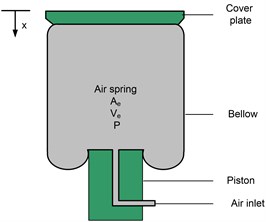
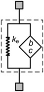
A rubber air spring composes of the cover plate, bellow and piston as shown in Fig. 1. The bellow is made of rubber with the fabric reinforced rubber wall. The piston and cover plate are made of plastic or metal, aiming to seal the ends of the rubber bellow. Additionally, the rubber bellow can also roll on the surface of the piston. During operation, the effective volume and area of the rubber air spring are changed and a function with respect to the displacement due to the piston shape and the variable contact area between the cover plate and inflated bellow.
Fig. 1The physical model of a rubber air spring
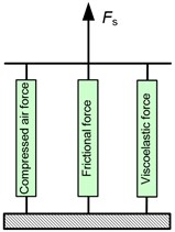
The resultant force generated by the rubber air spring is contributed by the thermodynamic force of the compressed air, the frictional force contributed by the relative motion the between the rubber and fabric as well as rubber bellow and the surface of the piston, and the viscoelastic force of the rubber material. Through the principle of superposition, the total force () of the rubber air spring is shown in Fig. 2, meaning that it is expressed as following:
where , and are forces generated by the compressed air, friction and viscoelastic, respectively.
Fig. 2a) Basic model of the rubber air spring force; b) complex dynamic stiffness
a)
b)
2.1. Compressed air force
Assuming that the heat exchange in the rubber bellow as well as air leakage is ignored, according to the thermodynamic theories and ideal air state equation, the mathematical model of the pressure () in air spring is determined as follows:
where, is the effective volume of the inflated bellow, is the polytropic exponent which depends on the thermodynamic state of the compressed air including 1 for the isothermal state, 1.4 for the adiabatic state and 1 1.4 for the polytropic process.
Form Eq. (2), the pressure inside the inflated bellow at an arbitrary compressed position is obtained as following:
where and are the initial pressure and effective volume
The compressed air is determined as following:
in which is the atmosphere pressure, is the effective area of the air spring.
The stiffness () of compressed air is defined by differentiating of Eq. (4) with respect to the displacement , we have:
The stiffness model given in Eq. (5) can be linearized around the working height as following:
in which the volume, effective area and pressure at the working height are denoted by , and . , are the change rate of the effective area and volume.
2.2. Frictional force
As presented above, the frictional force is generated by filled rubber components and relative motion between the rubber bellow and the surface of the piston. The friction is one of the causes creating the hysteresis behavior of the restoring force of a rubber air spring. Berg [22] proposed a model of frictional hysteresis as described as following:
in which: is the reference force along with the displacement called the reference state (, ), is the maximum friction force, is the displacement at which the friction force is increased to the value of /2. is an auxiliary quantity which is equal to / ranging from –1 to 1.
When the air spring is excited by a harmonic signal with the amplitude and frequency , the steady-state amplitude of the frictional force is expressed:
The stiffness and phase angle for the friction model are determined:
with .
Fig. 3Friction force with respect to displacement
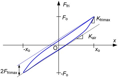
As shown in Fig. 3 is the maximum tangent stiffness as the displacement is close to . The dot lines are representative for the stiffness , the vertical distance between these lines approximately equals 2. The displacement is obtained as below:
2.3. Viscoelastic force
Rubber air springs also inherent viscoelastic behaviors of rubber material. There are some the viscoelastic models of material studied and proposed as Zener model, Maxwell model, Kelvin-Voigt model and fractional model, etc. Among them fractional Kelvin-Voigt model [23] enables a good fit to the hysteresis behavior due to the viscoelasticity of the rubber bellow. This model is described as a spring with the stiffness in parallel spring pot with the parameters , 0 1 as shown in Fig. 4.
The motion equation of the fractional Kelvin-Voigt model () is obtained as following:
in which is the fractional derivation of the displacement versus the time. By applying the definition of Grunwald fraction derivative [24], we have:
in which and is integer.
Fig. 4Fractional Kelvin-Voigt model
In order to present the complex stiffness of fractional Kelvin-Voigt model, the Fourier transform of Eq. (12) is realized as below:
By substituting into Eq. (14), the complex dynamic stiffness and phase angle of the fractional Kelvin-Voigt model are obtained as below:
in which ; .
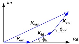
As a result, the resultant dynamic stiffness vector of the rubber air spring is shown in Fig. 2(b) and is expressed as following:
During operation, the energy is not lost by force generated by compressed air meanwhile both the frictional and viscoelastic forces cause the energy dissipation.
Supposing an excitation , according to [23], the fractional derivation with respect to the displacement is expressed as following:
The motion equation of the fractional Kelvin-Voigt model can be written:
The hysteresis loop of the fraction Kelvin-Voigt model is expressed as below:
The optimal values of , , and will be identified through minimizing the following cost function:
where is the number of the harmonically excited signal, , are the viscoelastic forces at the time having the corresponding displacement equaling 0 and .
3. Experimental apparatus
The test-rig is set up as shown in Fig. 5 in which the rubber air spring manufactured by Guangzhou Guomat Air spring Co., Ltd is inflated by the air reservoir through the switch valve whilst the internal pressure of the bellow is regulated by the pressure regulator. One end of the air spring is excited by the pneumatic cylinder controlled by the proportional valve while the other is fixed to a support plate where the force can be measured through a load cell with model “HPS”. Besides, the pressure inside the rubber bellow is measured by the pressure transducer-EDS.305. A computer in which a NI-card 6221 worked as an A/D converter is installed for communicating between the computer and sensors, is used to monitor as well as collect the data from sensors.
Fig. 5Experimental setup: a) photograph of the test rig; b) schematic of the test rig
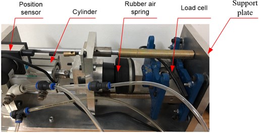
a)
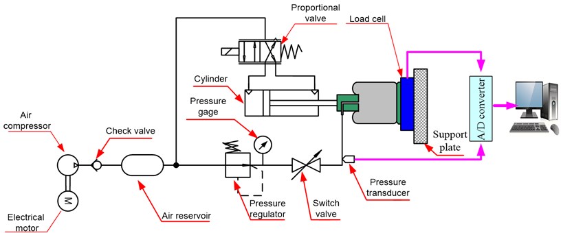
b)
4. Identified results and model verification
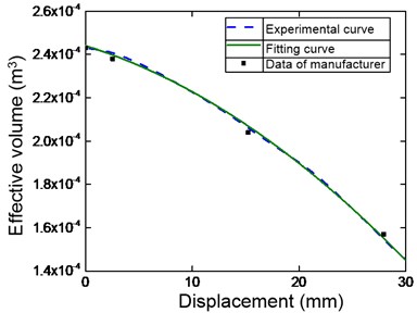
First of all, the effective area and volume will have been predicted, before experimental data collection, the rubber bellow is inflected by the air reservoir to value of 1.5 bar. Then the free end of the rubber air spring is excited by sinusoidal displacements having amplitude of 15 mm and very low frequency of 0.005 Hz, aiming to ignore the effects of viscoelasticity of material. The real force and internal pressure are collected and applying Eq. (3) obtains the effective area curve versus the displacement as shown by the dashed line in Fig. 6(a). Simultaneously, the effective volume of the rubber air spring is predicted through Eq. (2) in which the initial volume of the bellow is 0.243 liter provided by the company and the polytropic exponent () is set at value of 1 due to the low velocity of the cylinder. The result is to attain the predictive curve of the effective volume depicted by the dashed line as shown in Fig. 6(b). It is interesting to confirm that the predictive curve follows well the experimental data (marked by the filled squares) given by the company.
To simplify restoring force model analysis of the rubber air spring, the predicted effective area () and volume () is approximately expressed by polynomial functions as given in Eqs. (21-22) where the Least square method is employed to find the coefficients of the polynomial so that the error between fitting function and predicted result is the minimum. As observed in Fig. 6, the fitting curves are in a good agreement with the predicted data:
Fig. 6Fitting curve compared with the predicted results: a) effective area; b) effective volume (Annotation for line types is given in right-corner panel of figure)
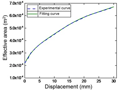
a)
b)
Next, a displacement with amplitude of 10 mm and frequency of 0.02 Hz is applied on the free end of the rubber air spring to obtain the frictional hysteresis loop as shown in Fig. 7 (the detailed notion of the line types is presented in the left-top corner panel of the figure). It can be seen obviously that the sharp corners appear at minimum and maximum displacements of the hysteresis loop. By applying Berg’s model, the predicted curves of the fictional hysteresis loops are drawn by the solid line. It confirms that the Berg’s model offers (where 5.7 N and 1.95 mm) a good fit to the hysteresis loop due to the effects of friction.
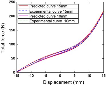
Next, the dynamic test with the frequencies of 0.1 Hz, 0.2 Hz, 0.5 Hz, 1 Hz, 1.5 Hz, 2 Hz, 2.5 Hz, 3 Hz, 4 Hz, 5 Hz, 6 Hz, 7 Hz and the amplitude of 8 mm is realized to predict the viscoelastic model. By utilizing genetic algorithm (GA) with aiming the minimum of the cost function expressed by Eq. (20), the optimal values of the parameters , , are 1.325; 0.909; and 0.859, respectively. Then, the predicted curve of the restoring force model is shown in Fig. 8. Obviously, the restoring force model of the rubber air spring and the experiment one match well together. The hysteresis loop generated by a displacement having small amplitude is enclosed in the loop for large amplitude and the sharp corners are appeared at the ends of the displacement. The more the reduction in amplitude, the more the slope of the hysteresis curve is increased. Especially, comparing with Fig. 7, increasing the frequency will lead to reduce the effect of the hysteresis.
Fig. 7Comparing Berg’s model and experiment one
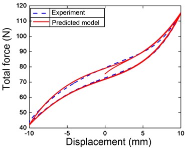
Fig. 8Force-displacement hysteresis loop compared the experiment and identification
5. Conclusions
In this paper, the analysis model of the restoring force of a commercial rubber air spring was established and analyzed. These meaningful conclusions of the study are presented as following: (1) The restoring force model of the rubber air spring was presented, including the contribution of compressed air, friction and viscoelastic of the rubber bellow. (2) The experiment model was set up for collecting data to identify the structure parameters through genetic algorithm. (3) The proposed model of the rubber air spring was evaluated experimentally showing that the experimental results illustrate the good follow among the analysis model and the experimental data. (4) The identification of rubber air spring was carried out successfully that leads to the noteworthy application of the air spring for vibration isolation field.
References
-
I. Kovacic, M. J. Brennan, and T. P. Waters, “A study of a nonlinear vibration isolator with a quasi-zero stiffness characteristic,” Journal of Sound and Vibration, Vol. 315, No. 3, pp. 700–711, Aug. 2008, https://doi.org/10.1016/j.jsv.2007.12.019
-
T. D. Le and K. K. Ahn, “A vibration isolation system in low frequency excitation region using negative stiffness structure for vehicle seat,” Journal of Sound and Vibration, Vol. 330, No. 26, pp. 6311–6335, Dec. 2011, https://doi.org/10.1016/j.jsv.2011.07.039
-
J. Xu and X. Sun, “A multi-directional vibration isolator based on quasi-zero-stiffness structure and time-delayed active control,” International Journal of Mechanical Sciences, Vol. 100, pp. 126–135, Sep. 2015, https://doi.org/10.1016/j.ijmecsci.2015.06.015
-
S. Santillan, L. N. Virgin, and R. H. Plaut, “Equilibria and vibration of a heavy pinched loop,” Journal of Sound and Vibration, Vol. 288, No. 1-2, pp. 81–90, Nov. 2005, https://doi.org/10.1016/j.jsv.2004.12.016
-
E. J. Chin, K. T. Lee, J. Winterflood, L. Ju, and D. G. Blair, “Low frequency vertical geometric anti-spring vibration isolators,” Physics Letters A, Vol. 336, No. 2-3, pp. 97–105, Mar. 2005, https://doi.org/10.1016/j.physleta.2005.01.013
-
R. H. Plaut, H. M. Favor, A. E. Jeffers, and L. N. Virgin, “Vibration isolation using buckled or pre-bent columns-Part 1: Two-dimensional motions of horizontal rigid bar,” Journal of Sound and Vibration, Vol. 310, No. 1-2, pp. 409–420, Feb. 2008, https://doi.org/10.1016/j.jsv.2007.09.037
-
S. Liu, P. Su, J. Wu, and Y. Fang, “A study of a nonlinear magnetic vibration isolator with quasi-zero-stiffness,” Journal of Vibroengineering, Vol. 20, No. 1, pp. 310–320, Feb. 2018, https://doi.org/10.21595/jve.2017.18602
-
B. Yan, H. Ma, C. Zhao, C. Wu, K. Wang, and P. Wang, “A vari-stiffness nonlinear isolator with magnetic effects: Theoretical modeling and experimental verification,” International Journal of Mechanical Sciences, Vol. 148, pp. 745–755, Nov. 2018, https://doi.org/10.1016/j.ijmecsci.2018.09.031
-
G. S. Prassad and M. K. Mohan, “A contemporary adaptive air suspension using LQR control for passenger vehicles,” ISA Transactions, Vol. 93, pp. 244–254, Oct. 2019, https://doi.org/10.1016/j.isatra.2019.02.031
-
H. Li, S. Li, W. Sun, L. Wang, and D. Lv, “The optimum matching control and dynamic analysis for air suspension of multi-axle vehicles with anti-roll hydraulically interconnected system,” Mechanical Systems and Signal Processing, Vol. 139, p. 106605, May 2020, https://doi.org/10.1016/j.ymssp.2019.106605
-
A. Malshakov and A. Akzholov, “Method to determine required amount of spare parts for air suspension in large-size buses,” Transportation Research Procedia, Vol. 50, pp. 414–421, 2020, https://doi.org/10.1016/j.trpro.2020.10.049
-
N. Y. P. Vo and T. D. Le, “Adaptive pneumatic vibration isolation platform,” Mechanical Systems and Signal Processing, Vol. 133, p. 106258, Nov. 2019, https://doi.org/10.1016/j.ymssp.2019.106258
-
G. Quaglia and M. Sorli, “Air suspension dimensionless analysis and design procedure,” Vehicle System Dynamics, Vol. 35, No. 6, pp. 443–475, Jun. 2001, https://doi.org/10.1076/vesd.35.6.443.2040
-
S. J. Lee, “Development and analysis of an air spring model,” International Journal of Automotive Technology, Vol. 11, No. 4, pp. 471–479, Aug. 2010, https://doi.org/10.1007/s12239-010-0058-5
-
H. Liu and J. C. Lee, “Model development and experimental research on an air spring with auxiliary reservoir,” International Journal of Automotive Technology, Vol. 12, No. 6, pp. 839–847, Dec. 2011, https://doi.org/10.1007/s12239-011-0096-7
-
B. Zargar, A. Fahim, and A. Jnifene, “Development, validation, and parameter sensitivity analyses of a nonlinear mathematical model of air springs,” Journal of Vibration and Control, Vol. 18, No. 12, pp. 1777–1787, Oct. 2012, https://doi.org/10.1177/1077546311426250
-
T. Mankovits and T. Szabó, “Finite element analysis of rubber bumper used in air-springs,” Procedia Engineering, Vol. 48, pp. 388–395, 2012, https://doi.org/10.1016/j.proeng.2012.09.530
-
V. Gavriloski and J. Jovanova, “Dynamic behavior of an air spring element,” FME Transactions, Vol. 42, No. 4, pp. 305–310, 2014.
-
X. Li, Y. He, W. Liu, and Y. Wei, “Research on the vertical stiffness of a rolling lobe air spring,” Proceedings of the Institution of Mechanical Engineers, Part F: Journal of Rail and Rapid Transit, Vol. 230, No. 4, pp. 1172–1183, May 2016, https://doi.org/10.1177/0954409715585370
-
M. M. Moheyeldein, A. M. Abd-El-Tawwab, K. A. Abd El-Gwwad, and M. M. M. Salem, “An analytical study of the performance indices of air spring suspensions over the passive suspension,” Beni-Suef University Journal of Basic and Applied Sciences, Vol. 7, No. 4, pp. 525–534, Dec. 2018, https://doi.org/10.1016/j.bjbas.2018.06.004
-
M. Berg, “A model for rubber springs in the dynamic analysis of rail vehicles,” Proceedings of the Institution of Mechanical Engineers, Part F: Journal of Rail and Rapid Transit, Vol. 211, No. 2, pp. 95–108, Mar. 1997, https://doi.org/10.1243/0954409971530941
-
M. Berg, “A non-linear rubber spring model for rail vehicle dynamics analysis,” Vehicle System Dynamics, Vol. 30, No. 3-4, pp. 197–212, Sep. 1998, https://doi.org/10.1080/00423119808969447
-
R. Lewandowski and B. Chorążyczewski, “Identification of the parameters of the Kelvin-Voigt and the Maxwell fractional models, used to modeling of viscoelastic dampers,” Computers and Structures, Vol. 88, No. 1-2, pp. 1–17, Jan. 2010, https://doi.org/10.1016/j.compstruc.2009.09.001
-
I. Podlubny, Fractional Differential Equations, Academic Press, 1999.
About this article

