Abstract
To assess the effect of the mass-stiffness distribution of the cab and vibratory roller on the ride quality, the acceleration-frequency characteristics of the isolation systems are researched based on the nonlinear dynamic model of the vehicle. The complex domain is used to solve the vibration equations in the frequency region. The effect of the mass and stiffness parameters of the cab and vehicle is then analyzed via MATLAB software. The research results show that the resonant frequency of the cab's isolations and their acceleration-frequency is insignificantly affected by the mass-stiffness distributions in the case of without the excitation of the vibrator drum. Conversely, under an excitation 28 Hz of the vibrator drum, the mass-stiffness distributions strongly affect on the acceleration-frequency of the cab isolations, especially, when increasing the stiffness coefficient and reducing the cab mass with 1.5, the vehicle’s ride quality and structural durability of the vibratory rollers are greatly improved.
Highlights
- The vibration problem of the vibratory rollers is solved.
- The resonant frequency of the cab's isolations and their acceleration-frequency is insignificantly affected by the mass-stiffness distributions in the case of without the excitation of the drum.
- The mass-stiffness distributions strongly affect on the acceleration-frequency of the cab isolation under the excitation of drum.
- When increasing the stiffness coefficient x= 1.5 and reducing the cab mass x = 1.5, the vehicle's ride quality and structural durability of the vibratory rollers are greatly improved.
1. Introduction
The cab isolation system of the vibratory rollers was used to reduce the transmission vibration from the vibrator drum and the road surface to the driver [1]. In the previous researches of vibratory rollers showed that the vehicle's ride comfort was strongly affected by the vibration excitations of the drum and road surface [1-3], thus, the cab isolations were continuously researched and developed. The structure of the traditional rubber mounts equipped on the vibratory roller cab was re-designed and optimized to improve the ride comfort [2]. However, the obtained performance of those optimal rubber mounts was very small. Thus, the hydraulic and pneumatic mounts were researched [3]. The result showed that the performance of the hydraulic mounts (HM) was better than other isolations on improving the ride comfort. The HM was then controlled by using the optimal FLC-PID controller to further improve the ride comfort [4-6]. Besides, a damper hydraulic mount was also added in the cab isolations to enhance the ride comfort [7, 8]. A damper mount in the horizontal direction was also added in the cab isolations [9]. Its damping coefficient was then controlled to reduce the cab shaking of vibratory rollers [10]. To further improve the ride comfort and control the cab shaking, the hydro-pneumatic mounts were researched for the vibratory roller cab [11-13]. All the research results showed that the driver's ride comfort and cab shaking were greatly improved by applying the optimal control for the cab isolations. However, in all the existed researches, the vibration equations of the vibratory rollers and their isolations were mostly solved in the time region.
The ride quality was not only affected by the vibration excitation in the time region but also greatly affected by the frequency excitation below 10 Hz [14, 15]. To reduce the effect of the resonant under the low-frequencies, the specific vibration frequency of the cab isolations should be designed in a range below 2.5 Hz [16]. However, this specific vibration frequency was strongly depended on the cab mass and stiffness of the isolation system. Thus, it is necessary to study the effect of the mass-stiffness distribution of the cab and isolations on the acceleration-frequency characteristics to reduce the vibration resonance and enhance the stability and durability. Therefore, a nonlinear vibratory roller dynamic model is established to analyze the effect of the mass-stiffness distribution on the characteristics of the acceleration-frequency of the cab isolations in the low-frequency region. The complex domain is then applied to calculate the vehicle’s vibration equations. The mass and stiffness parameters of the vehicle and isolations are simulated to evaluate the results.
2. Vehicle model and vibration equation in the time region
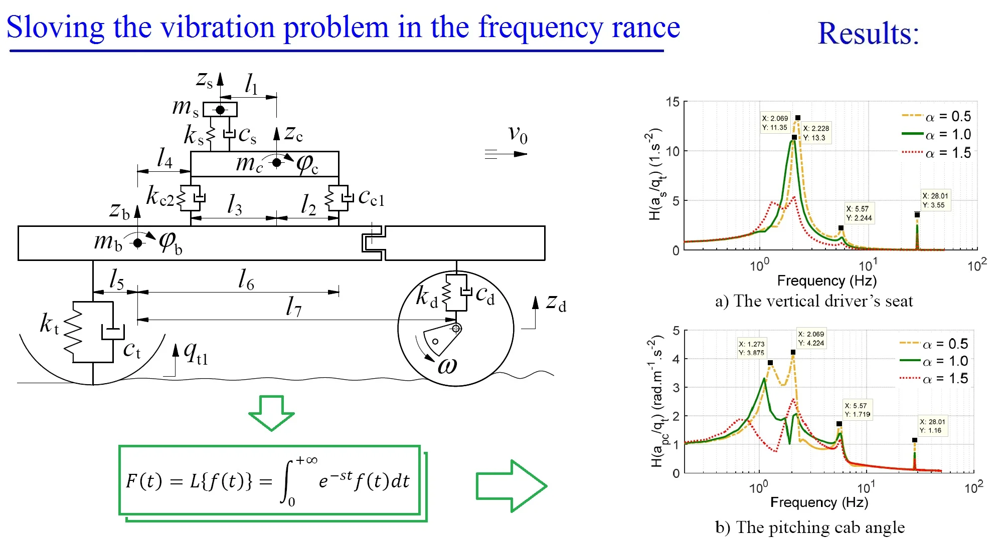
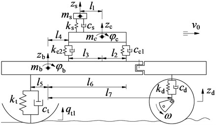
Based on the actual structure of the vibratory roller, a nonlinear vehicle model is then established to calculate the different dynamic equations of the vehicle, as modeled in Fig. 1, where and are the vertical motions of the driver’s seat, cab, vehicle body and the pitching motions of the cab and vehicle body. and are the damping and stiffness coefficients of the isolations of the driver’s seat, cab, vibrator drum, and tire, respectively. , , and are the mass of the driver’s seat, cab, vehicle body, respectively. is the longitudinal distances of the vehicle. and are the vibration excitations.
Fig. 1The nonlinear dynamic model of the vibratory roller
Based on the vehicle model, the different dynamic equations are given as follows:
In previous researches, the vibration of vibratory rollers was mainly solved in the time region on improving the ride comfort [1-3, 8-9], the acceleration-frequency characteristic of the isolations of the cab and the vehicle in the frequency region gets very little attention. In this study, the acceleration-frequency characteristic of isolations is studied to analyze the results.
3. Vibration equations in the frequency region
To research the characteristics of the amplitude-frequency, it must be to calculate via the transfer function. Thus, a variable is applied to convert the unknown of the differential equations in the time region to the image function in the frequency region. Then, the numerical equations are calculated to search the transfer function of the Laplace. Finally, the transfer function of the frequency is determined by replacing , is the excitation frequency.
Based on the Laplace operator [14, 16], it is assumed that with the variable 0 is the original function and continuous in the range of [0, +∞], the image of and its derivative via Laplace transformation is given by:
It is assumed that at the initial time 0, the displacement and velocity of the vehicle is also equal to zero, thus, based on Eq. (2), the unknowns in Eq. (1) are described as follows:
Thus, Eq. (1) described via Laplace "" and replaced by and , we have:
where:
By dividing the Eq. (4) for the , the form of the matrix of Eq. (4) is then written by:
where are the vibration transfer functions from the road surface to the driver's seat, cab pitch angle, vehicle’s body, and vehicle pitch angle, respectively.
The matrix is defined based on the dynamic parameters of the vibratory roller, thus, the transfer functions of , , , , and are determined. The complex number values of in Eq. (5) are calculated by , , , , , , the absolute values of that expresses the relationship of the amplitude-excitation frequency and their acceleration amplitude-excitation frequency are given by:
4. Vibration excitations
In this study, two vibration types are considered including excitation of the vibrator drum at a frequency of 28 or 35 Hz and another vibration excitation from the road surface when the vehicle moving.
The excitation of the vibrator drum is determined by [3, 4]:
where and are the mass and eccentricity of the vibration excitation of the vibratory drum.
Besides, the vibration excitation from the road surface is also described as follows.
In the design of the isolation systems, the resonance frequency is always of particular concern. It is simulated and calculated based on the different vibration excitations of the system. The previous studies showed that the harmonic-function profile of the road surface often causes resonant vibrations in the isolation system, and it was used to evaluate the driver's ride comfort and health as well as the safety of designed structures [14, 16]. In this study, to evaluate the effect of the mass-stiffness distribution of the cab isolations on the driver’s ride comfort and safety of designed structures, the harmonic function of the road surface in Eq. (8) is used.
where and are the high road surface and frequency excitation of the road surface.
From Eqs. (7-8), their Laplace transformation in complex number domain is written by:
Based on the vibration excitation in Eq. (9) and dynamic parameters of the vehicle in Ref. [3], the calculation in the complex number domain of Eq. (5) are then performed to evaluate the acceleration-frequency characteristics of the isolations of the cab and the vehicle.
5. Simulations and discussions
The resonant frequency of the cab isolations, , depends on the cab mass and stiffness parameter of the isolation system. Thus, to optimize the driver's seat comfort and safety; as well as enhance the stability and durability of the structures, the effect of the mass-stiffness distribution on the characteristics of the acceleration-frequency need to be simulated and analyzed under the vibration excitation of the road surface and the vibrator drum. The dynamic parameters of the vibratory roller in Ref. [3], an excitation 28 Hz of the vibrator drum, and the vehicle speed at 6 km/h is used for the simulation process. Three cases of the increase of the stiffness coefficient and reduction of the cab mass , with 0.5, 1.0, 1.5 is simulated, respectively.
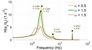
Fig. 2The acceleration-frequency responses without the excitation of the vibrator drum
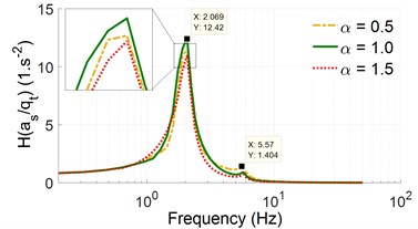
a) The vertical driver’s seat
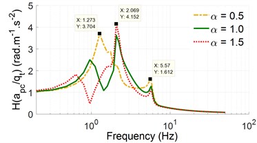
b) The pitching cab angle
Fig. 3The acceleration-frequency responses with an excitation of the vibrator drum, 28 Hz
a) The vertical driver’s seat
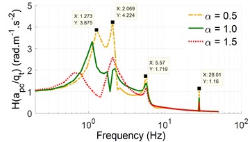
b) The pitching cab angle
Without the excitation of the vibrator drum, the simulation results of the acceleration-frequency of the driver’s seat and pitching cab angle are plotted in Fig. 2. The results show that the resonant frequencies with their high amplitude mainly appear in a range below 2.5 Hz. Thus, the specific vibration frequency of the cab isolations satisfies the design condition [15]. When the stiffness coefficient is increased by 0.5, 1.0, 1.5, concurrently, the cab mass is reduced by 0.5, 1.0, 1.5, respectively, the acceleration-frequency characteristic of the driver's seat is insignificantly changed, while that of the pitching cab angle appears at 1.273 Hz of 0.5 and 2.069 Hz at 1.0, 1.5 in a range below 2.5 Hz. However, these changes also insignificantly affect on the change of the high amplitude of the acceleration-frequency at the resonant frequencies. Thus, the change of the mass-stiffness distribution is insignificantly impacted on the ride quality as well as the safety and durability of the isolation’s structure.
With an excitation frequency, 28 Hz, of the vibrator drum, the simulation results in Fig. 3 indicate that the high amplitude of the acceleration-frequency characteristics of the driver's seat and pitching cab angle also mainly appear in a range below 2.5 Hz. However, under the effect of an excitation frequency 28 Hz and mass-stiffness distribution of the cab and cab’s isolations, the high amplitude of acceleration-frequency characteristics of the driver’s seat and pitching cab angle at 0.5 is strongly increased in comparison with the initial values 1.0. Thus, the reduction of the cab isolation's stiffness coefficient and the increase of the cab mass may have a negative impact on the ride quality and structural durability. Conversely, the increase of the stiffness coefficient and the reduction of the cab mass with 1.5, the high amplitude of acceleration-frequency characteristics of the driver’s seat and pitching cab angle is greatly reduced under various excitation frequencies. This research result has important implications for improving the ride quality and structural durability of the vibratory rollers, because the vibratory roller uses most of its time working on the workshop at an excitation 28 Hz of the vibrator drum [4, 5]. These results are similar to the results of vehicle's suspension systems in low-frequency below 4 Hz [14, 17]. It showed that to reduce the amplitude of the acceleration-frequency, the suspension stiffness needs to be increased, conversely, in the frequency range above 10 Hz, the suspension stiffness needs to be reduced to decrease the noise. To solve this problem, a pneumatic suspension with the changed airbag stiffness was applied [11, 12, 17].
6. Conclusions
A new simulation method based on the Laplace transfer function to research the vibratory roller's vibration in the frequency region is applied to analyze the vehicle's ride quality.
Without the excitation of the drum, the mass-stiffness distribution of the cab and cab’s isolation insignificantly impacts on the acceleration-frequency of the cab isolations.
With the excitation 28 Hz of the drum, the acceleration-frequency characteristic are strongly reduced with the increases of the stiffness coefficient and the reduction of the cab mass at 1.5, thus, the ride quality and structural durability of vibratory rollers are greatly improved.
References
-
Nguyen V., Le V., Development of cab isolation systems of off-road vibratory rollers: review research. Journal of Mathematical Models in Engineering, Vol. 6, 2020, p. 93-102.
-
Le V., Zhang J., et al. Experimental modal analysis and optimal design of cab’s isolation system for a single drum vibratory roller. Vibroengineering Procedia, Vol. 31, 2020, p. 52-56.
-
Nguyen V., Zhang J., et al. Vibration analysis and modeling of an off-road vibratory roller equipped with three different cab’s isolation mounts. Shock and Vibration, Vol. 2018, 2018, p. 8527574.
-
Van L., Jian R., et al. Low-frequency performance of semi-active cab’s hydraulic mounts of an off-road vibratory roller. Shock and Vibration, Vol. 2019, 2019, p. 8725382.
-
Nguyen V., Jian R., et al. Performance analysis of semi-active hydraulic system of the off-road vibratory roller cab using optimal fuzzy-PID control. Journal of Southeast University, Vol. 35, 2019, p. 399-407.
-
Zhang B., Van L. Comparing performance of cabin suspension system for a vibratory roller with optimal control methods. 6th International Conference on Systems and Informatics, Vol. 2019, 2019, p. 915-920.
-
Liem N., Nguyen K. Enhancing the ride comfort of the off-road vibratory roller cab by adding damper hydraulic mount. Vibroengineering PROCEDIA, Vol. 21, 2018, p. 89-95.
-
Van L., Zhang J., et al. Ride quality evaluation of the soil compactor cab supplemented the auxiliary hydraulic mounts via simulation and experiment. Journal of Southeast University, Vol. 35, 2019, p. 273-280.
-
Zhang B., Liem N., et al. Control the ride comfort of soil compactor with semi-active seat suspension and cab’s horizontal damper. Vibroengineering Procedia, Vol. 30, 2020, p. 91-96.
-
Van N., Ren Q., Van Q., et al. Study to control the cab shaking of vibratory rollers using the horizontal auxiliary damping mount. Mathematical Models in Engineering, Vol. 6, 2020, p. 57-65.
-
Nguyen V., Zhang J., Huang D. Low-frequency ride comfort of vibratory rollers equipped with cab hydro-pneumatic mounts. Journal of Southeast University, Vol. 36, 2020, p. 1-7.
-
Jiao R., Nguyen V., Le V. Ride comfort performance of hydro pneumatic isolation for soil compactors cab in low frequency region. Journal of Vibroengineering, Vol. 22, 2020, p. 1174-1186.
-
Wang P., Nguyen V., Zhang J. Experimental research and optimal control of vibration screed system (VSS) based on fuzzy control. Journal of Vibroengineering, Vol. 22, 2020, p. 1415-1426.
-
Ren Q., Van L. Studies on the low frequency vibration of the suspension system for heavy trucks under different operation conditions. Journal of Noise and Vibration Worldwide, Vol. 51, 2020, p. 1-11.
-
Grifn M. Handbook of Human Vibration. Academic Press, London, UK, 1990.
-
Dang V. Influence of Structural Parameters and Operating on Vietnam’s Bus Ride Comfort. Ph.D. Thesis, Hanoi University of Science and Technology, Vietnam, 1996.
-
Nguyen V., Ren Q., Jian R. Control performance of damping and air spring of heavy truck air suspension system with optimal fuzzy control. SAE International Journal of Vehicle Dynamics, Stability, and NVH, Vol. 4, 2020, p. 179-194.
About this article

This work has been supported by the Key Scientific Research Project of Hubei Polytechnic University, China (No. 18XJZ02A) and National College Student Innovation and Entrepreneurship Training Project, China (No. 201910920001, No. 202010920003).
