Abstract
The traditional starting methods for induction motors are easy to cause excessive starting current, which causes serious damage to AC speed regulating system. With analysis on the essence of magnetic field control, A method on asynchronous motor pre-excitation starting based on flux linkage compensation deviation decoupling is proposed in this paper. Based on vector control, a DC flux linkage with stable amplitude and direction is established by using DC pre-excitation starting method. According to the fluctuation of flux linkage in dynamic process and the coupling of the system, flux compensation algorithm and deviation decoupling control are used to decouple the flux compensation and the system to realize the smooth starting of the motor. The experimental results show that the proposed method can effectively reduce the starting peak current and improve the starting performance.
Highlights
- The DC flux linkage with stable amplitude and direction is established.
- The flux compensation algorithm and deviation decoupling control are applied.
- The excitation current and torque current are set by DC pre-excitation control.
- Comparative experiments of several methods show the proposed method better performance.
1. Introduction
Although the asynchronous induction motors are widely used in various industry fields because of their simplicity and durability, the motor starting smoothly is the primary prerequisite for its ability to stable operation. Frequency conversion starts control on induction motors is becoming an important part of industry research. Generally, the induction motor starting performance is hoped that the torque responds rapidly to ensure the normal operation of machinery in the starting process, and the starting current is as small as possible to avoid the impact on the grid [1-3]. In actual application, especially to a large power induction motor, because of its large capacity and the moment of inertia is large, when the applied voltage is not suitable, it will produce a huge peak current. At the same time, the system must overcome the large static friction torque, and the motor output torque response is slow.
At present, the main modes of asynchronous induction motor starting are as follows: direct starting, auto-transformer reduced voltage starting, Y-Δ buck starting, soft starting, frequency conversion starting, etc. Usually, a large power induction motor takes the way of frequency conversion to start, but the starting performance cannot meet the ideal requirement [4-8]. The experimental study has shown that in the 160 kW frequency control system, the motor starting peak current is up to 600 A, but the current of no-load steady-state operation is only 124 A [9]. Excessive impact current causes the motor itself to overheat, affects its working life, and damages the inverter switching. Because of the limited capacity of the supply transformer, it causes the grid voltage drop and affects the normal use of equipment around, even the motor itself cannot start. Furthermore, the response of the motor electromagnetic torque is not very fast.
In recent years, a variety of research methods based on the vector control theory have been taken to improve the motor start performance. Reference [10] is based on constant (VVVF) control, although it has good speed performance, the promotion of the induction motor starting performance is not significant obviously. In reference [11], AC and DC pre-excitation start methods are proposed mainly, but they are mainly used in the three-level inverter circuit. The induction motor flux model predictive control (MPC) is proposed to the induction motor starting [12], but its principle is simple, which is not constrained by nonlinear and multivariate, and the actual research of flux and torque need many experiments and simulations to determine the final weight coefficients.
In this paper, with the analysis on vector control application, it cannot be well applied directly to the starting of large-power induction motors. The starting current is very large to cause damage to power-conductors and the whole hoist system. A novel pre-excitation control strategy is proposed in this paper. A magnetic field is built in large power motor starting firstly, in which DC pre-excitation is adopted and the rotor flux orientation is set to coincide with the center line of motor’s one phase winding. With the completion of this pre-excitation, the control strategy is switched to the conventional vector control. The excitation subsystem and the torque subsystem in the motor can be decoupled dynamically after this pre-excitation and indirect vector control. The experimental results show that the motor’s starting current rises smoothly, and its output torque has fast response. This control strategy is capable of reducing the motor’s starting current peak and improving the safety of induction motor’s starting.
In the rest of the article, Section 2 describes the reasons for the large start-up current of Induction motor and its analysis. Section 3 presents the pre-excitation starting method based on vector control, including space vector dynamic equations of induction motor, DC pre-excitation vector control method, and flux linkage amplitude compensation. Section 4 provides the overall design scheme on pre-excitation starting control. Section 5 shows the experiential process and results in analysis, in which the new induction motor pre-excitation starting control method proposed by this paper has better performance. The conclusion and discussion are given in Section 6.
2. Reasons for large start-up current of induction motor and its analysis
2.1. The internal coupling of induction motor
The dynamic mathematical model of the induction motor is a nonlinear, high order, and strong coupling multi-variable system. Based on the rotation orthogonal coordinate system, the mathematical model of the stator voltage of the motor is as follow:
where and are stator voltages under coordinate system, and are stator currents under coordinate system, is stator resistance, is stator inductance, is mutual inductance, is synchronized angular velocity, and are rotor fluxes under coordinate system, is differential operator, is the motor leakage coefficient, is rotor inductance. From Eq. (1), it can be seen that the axis voltages are determined by the impedance voltage drop, the counter electromotive force, and the cross-coupling voltage generated by the axis, and the subsystems are coupled with each other. The third term of in Eq. (1), cross-coupling voltage , is the main factor of coupling. It makes the actual output current value not be good for given current value tracking, reduces the current loop bandwidth [13], and directly affects the start performance of the motor.
Due to the effect of the system coupling, improper control method will make axis voltage , exit deviation with the expected value, and result in voltage vector overshoot. This situation leads to the motor stator current overshoot, namely the starting impact current.
2.2. The fluctuation of the flux linkage amplitude
In the vector control of the induction motor, flux Linkage oriented is the key and used for decomposing the stator current to control the magnetic field and torque. However, the orientation accuracy is affected mainly by the motor parameters. In the actual operation, parameters of the motor often change with the saturation level of regular frequency, temperature, and magnetic, so that the magnetic field orientation is not accurate, which has a serious effect on the dynamic and static performances of the control system.
Fig. 1The influence of the inaccuracy of magnetic field orientation
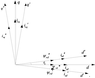
When the magnetic field orientation is not accurate, the flux initial phase 0, shown in Fig. 1. The flux linkage will not be able to maintain complete synchronization with the axle , and the projection component of the axle is not zero. Due to the dynamic nature of the system, the flux linkage amplitude fluctuates [14], which will cause the actual excitation current is not equal to the given excitation current and the system cannot achieve the optimal excitation [15, 16]. By the synthesis of the vector, the stator current is more than the expected value , and the start current is too large [17].
3. Pre-excitation starting method based on vector control
3.1. Space vector dynamic equations of induction motor
The equations of the space vectors of the induction motor are as follows:
where is stator voltage, is stator current, is stator flux, is rotor voltage, is rotor current, is rotor flux, is slipping angular velocity:
where is stator inductance, is rotor inductance, is mutual inductance:
where and are the variable lengths, is pole-pairs, is the space slip angle between the stator current vector and the rotor flux vector.
Eqs. (2), (3) and (4) are combined into new equations, as follows:
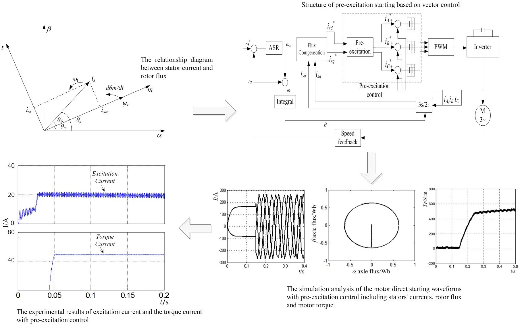
where is rotor time constant. The relationship diagram between stator current and rotor flux is shown in Fig. 2.
Fig. 2The relationship diagram between stator current and rotor flux
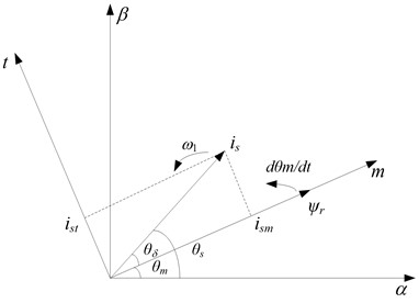
The above equation can have the following vector transformation in the complex plane coordinate system, namely: , , is angular of stator current vector and axis, is angular of axis and axis, then:
Eq. (7) is taken into Eq. (6), as follow:
The amplitude of stator current is obtained as follow:
In Fig. 2, it is obvious that is space slip angle between stator current vector and rotor flux vector :
In the process of the conventional motor starting, when the flux linkage is been established, the amplitude magnitude of and the angular speed change, which makes the angle between vector and not maintain a constant [18]. With the above analysis, it can be known that the unstable flux linkage makes the motor stator current fluctuate to generate the peak current.
Because of , Eq. (8) can be rewritten as follow:
The above equations are transferred into (special case of ) coordinate system:
where and are stator currents under coordinate system:
Obviously, the start performance of the motor is improved by controlling and . This control strategy makes rotor flux vector amplitude and invariant when the motor starts and 0. Eq. (10) can be simplified to as follow:
where, is constant, so and are synchronous. Because of , the slip frequency is deduced by . At this time, the amplitude of the stator current is as follow:
The start electromagnetic torque is obtained as follow:
When the same starting torque is obtained, the amplitude of the stator current vector can be reduced, namely the motor start peak current is reduced.
3.2. DC pre-excitation vector control method
For the realization of the above control idea, in the process of motor starting, the pre-excitation control makes rotor flux vector amplitude remain constant. With the given value (determined by the size of the actual load torque), the rotor flux vector of the motor start is as follow:
The specific implementation method of pre-excitation is as follows: the rotor flux linkage is oriented on the -phase winding, which is coincident with the center-line of the -phase winding, namely 0o. The flux linkage vector is established firstly, and then the torque is established.
The value of the excitation current is set by vector control on the stator voltage excites to the motor, and the currently limited link is added. In the establishment’s process of flux linkage, when the excitation current exceeds the set value, the stator voltage switches to zero vector, so that the stator voltage does not work and the excitation current keeps maximum value. When the excitation current is less than the set value, the stator voltage switches to a fixed nonzero vector, and the excitation current is increased, so that it repeatedly works in the current limiting range, namely using the PWM DC chopper method to control the value of the excitation current, whose purpose is to set up an appropriate magnitude and fix direction flux linkage before the motor starts. The control mode of the excitation current is as follows:
When the motor starts at low frequency, the vector voltage of the stator side is decreased. The main reason is the frequent emergence of the small vector. The large vector and zero vector are mainly used in pre-excitation control.
The pre-excitation vector control uses rotor flux linkage oriented, which realizes the decoupling effect of the excitation system and torque system. However, the fluctuation of the flux linkage amplitude mentioned above has not been solved very well.
3.3. Flux linkage amplitude compensation
The voltage equation of the induction motor in the coordinate system is as follow:
where and are the stator voltage components of in coordinate system, and are the rotor voltage components of in coordinate system, is the mechanical angular velocity.
In ideal conditions, the stator voltage vector orientation is accurate and the flux linkage can be ensured to be stable under the control. From Eq. (19) it can be obtained as follows:
Therefore, the stator voltage in the coordinate system is expressed by Eq. (20):
In the control system, the voltage is the order and the amplitude of the flux linkage is a feed-forward given constant, which can realize the tracking control of the current in real-time [19].
In the stator voltage vector control system, the stator current is decomposed into and , which are controlled respectively. If is kept as the constant, the amplitude of the flux linkage is constant. However, because the motor is running at low frequency, the stator resistance consumes most of the stator terminal voltage, the excitation voltage reduces, and the flux linkage amplitude reduces and fluctuates. At the same time, when is controlled by the current feedback loop, the output of the current controller is the directive voltage of the axis [20, 21], which has a certain deviation with the axis expected voltage in ideal condition. Therefore, it is difficult to realize the voltage vector directional accurately, and the system has no compensation for the error of flux linkage amplitude, which cannot guarantee the flux linkage amplitude stable. Ultimately, those reasons make the stator current too large in the start process.
Therefore, in the dynamic process, to ensure the stator flux linkage amplitude stable, it needs to introduce the flux linkage amplitude error compensation, namely that the feedback current value is introduced to estimate the magnitude of the stator flux linkage. From Eqs. (20) and (21), the flux linkage amplitude can be obtained as follow:
The amplitude error of stator flux linkage compensation is obtained as follows:
where and are ratio coefficient, is the error compensation signal, and .
4. Overall design scheme on pre-excitation starting control
Because of the system’s coupling and the fluctuation of the flux linkage amplitude, which leads the start current to too large, an induction motor pre-excitation starting method based on flux linkage compensation with vector control is proposed in this paper. The structure of this system is shown in Fig. 3.
Fig. 3Structure of pre-excitation starting based on vector control
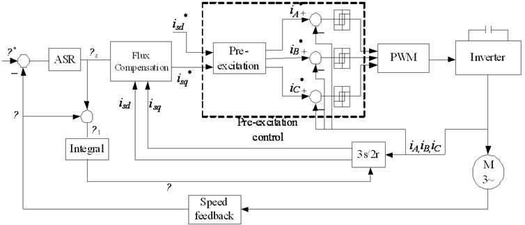
The flux linkage compensation is adopted to control the flux linkage amplitude in real-time. The fluctuation of the flux linkage amplitude is restrained. In the process of pre-excitation, excitation current and torque current can be controlled respectively, in which a magnetic field can be established in advance and the decoupling of the excitation subsystem and the torque subsystem is realized to start the motor. The method ultimately decreases the motor starting peak current.
The amplitude of excitation current is set up by vector control theory:
When the system is stable and the torque is fixed, the motor stator current is obtained as following [22-24]:
When Eq. (26) is equal, , namely , the stator current is the smallest, thus the excitation current is:
Generally, the limited range of excitation current is between about 95 % to 105 % of the given value .
In the process of pre-excitation, 0, . By Eq. (25), the stator current is ; at the same time, because of 0, which is substituted into Eq. (15), it can be obtained as: . It can be seen that the above two analyses are consistent with each other.
From Eq. (25), it is obvious that the stator current is minimum when the excitation current is equal to the torque current (MTPA principle), and the value of the current excitation has been controlled in pre-excitation. The torque current is controlled by PWM with the ramp function, which is equal to the excitation current. The motor begins starting when the above requirements are met. This method can ensure stator current is minimum and reduce the peak current.
Torque’s response follows the variations of the torque current. When the motor starts instantly, the voltage vector and the excitation current are controlled to be orthogonal, namely that the voltage vector coincides with flux, which can produce the maximum change rate of torque. However, because at this moment the voltage vector changes suddenly, the flux linkage amplitude fluctuates. Its error compensation can be well to ensure the flux linkage amplitude is stable to maintain the start current smooth and stable as well as the torque response is faster.
During DC pre-excitation, the initial phase angle of flux linkage is set to zero, and the torque current is set to zero. The excitation current and the torque current in the coordinate system are transformed by 2/2 and 2/3 The stator three-phase current during pre-excitation can be obtained as follows:
After pre-excitation and complete decoupling control, the electromagnetic torque is only controlled by the torque current , and its variation law is as follows:
where is the slope of the torque-current function. It can be seen that the output of the torque is zero during the pre-excitation period. Torque can be tracked quickly with the torque-current in the whole process, and the dynamic response speed is relatively fast.
The pre-excitation starting method based on vector control improves the starting performance of the induction motor only through the control algorithm, without adding complex hardware. It is a very economical control method.
5. Experimental and results analysis
5.1. Simulation and analysis
Based on the above research, the simulation model of the pre-excitation control method is built in the Simulink platform, shown in Fig. 4, and the specific parameters of this simulation are 380 V, 80 KW, 50 Hz. In the starting control scheme, the initial phase angle is orientated and the amplitude of the rotor flux linkage is also set accordingly by the pre-excitation control. The torque current control is controlled appropriately after the flux linkage of the motor is on a steady state. The two subsystems between excitation and torque are realized to decouple dynamically in the control scheme.
Fig. 4Simulink platform model of pre-excitation control method
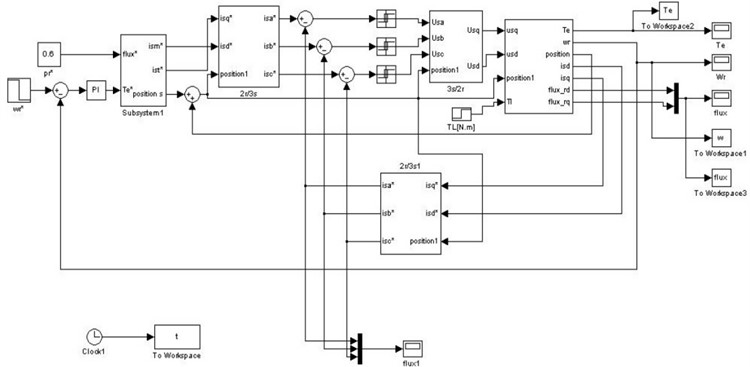
Fig. 5The motor direct starting waveforms without pre-excitation control
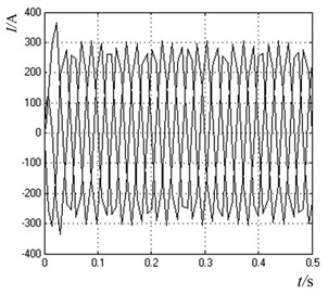
a) Three-phase stator current
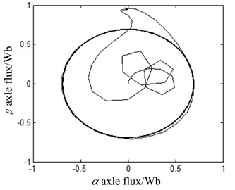
b) Rotor flux
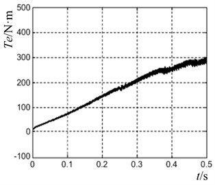
c) Motor torque
The motor direct start simulation waveforms without pre-excitation control are shown in Fig. 6. From Fig. 5(a), it can be seen that when the motor starts directly under full load, the peak value of the three-phase current of the stator is close to 380 A, and the steady current is close to 280 A, and the current has obvious overshoot phenomenon. In Fig. 5(b), the initial time of flux linkage establishment varies irregularly, the overall fluctuation is large, and the tracking is poor. At the same time, the magnitude of flux linkage is overshoot, which easily results in the occurrence of inrush current. In Fig. 5(c), the speed of torque response is relatively slow. At 0.3 s, the electromagnetic torque is about 220 N m, which is not stable and is still rising.
The simulation waveforms of induction motor pre-excitation start method based on flux linkage compensation deviation decoupling are shown in Fig. 6. In Fig. 6(a), the three-phase current of the stator during pre-excitation is direct current, and there is no peak current when starting. The maximum current is only about 270 A, which is equal to the steady-state current. The current rises smoothly and transits smoothly, and the whole process is relatively stable. In Fig. 6(b), the flux linkage established before starting makes the flux fluctuation smaller, achieves the expected steady-state value, avoids overshoot and oscillation, and compensates its trajectory to be more circular through the flux linkage. In Fig. 6(c), the output of torque during pre-excitation is zero, and the dynamic response speed of motor torque following the torque current is faster according to the set torque mode. When 0.3 s, the torque is about 490 N.m, which is close to the stable state.
Fig. 6The motor direct starting waveforms with pre-excitation control
a) Three-phase stator current
b) Rotor flux
c) Motor torque
5.2. The experiment and result analysis
The experimental platform is established to verify the proposed method, shown in Fig. 7, in which the hardware circuit of the “AC-DC-AC type hardware circuit” is adopted, and the pre-excitation control method of the motor is designed with a DSP core chip.
The hardware circuit completes the function of power supply from AC to DC to DC, voltage and current detection, over current protection. The main functions of the DSP chip are controlled by the corresponding software program, speed acquisition, vector control. The specific parameters of the motor are: 380 V, 30 KW, 50 Hz, 2, 0.315 Ω, 0.118 Ω, 1.43 mH, 3.37 mH, 3.55 mH. The switching sequence for the converter with SVPWM is 5 kHz.
Fig. 7The experimental platform of induction motor starting control
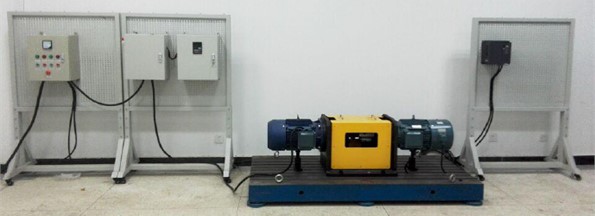
Fig. 8DC side voltage
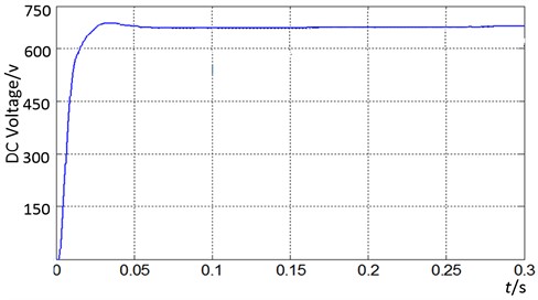
The DC bus link voltage detection waveform, as shown in Fig. 8. With the divider resistances, the voltage of the DC bus can be calculated by multiplying the voltage multiple of the detection circuit. It can be seen that the voltage response is fast and the voltage fluctuation is very small. The average voltage of the DC side voltage is stable at about 660 V.
Fig. 9Output phase voltage and current with pre-excitation control
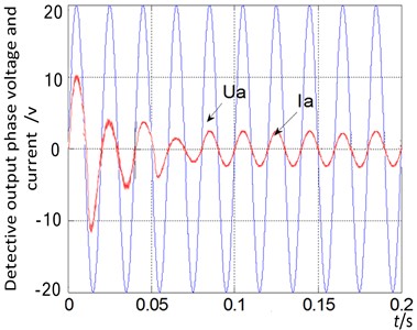
a) Without pre-excitation control
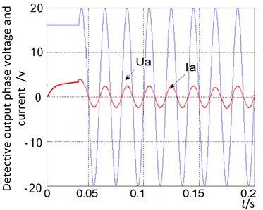
b) With pre-excitation control
Fig. 9. shows the detective waveforms of output phase voltage and current. is the inverter output phase voltage waveform processed by detection and capacitance filter circuit. Its amplitude is about 20 V and its frequency is about 50 Hz. is the inverter output current waveform passed through the detection circuit.
It can be seen from Fig. 9(a) that when the pre-excitation start-up is not used, the peak current of the start-up is close to 10 A, multiplied by the voltage divider of the detection circuit, and it is found that the peak current of the start-up time is too large. After the pre-excitation start-up scheme is adopted, shown in Fig. 9(b), it can be seen that the peak current at the start-up time is about 4 A, while the phase current of the motor rises steadily, which reduces the peak current at the start-up time.
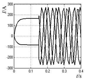
Fig. 10Excitation current and the torque current with pre-excitation control
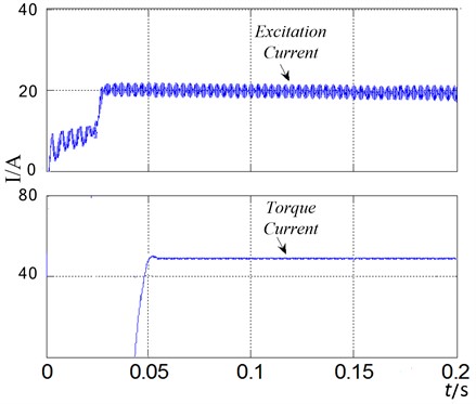
The waveforms of excitation current and the torque current with pre-excitation control are shown in Fig. 10, which are calculated and decoupled through the detection circuit and the control system. It is obvious that they rise relatively smoothly and achieve better tracking performance with pre-excitation starting and the decoupling effect is also good.
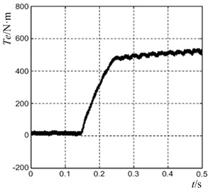
Fig. 11Motor torque waveform
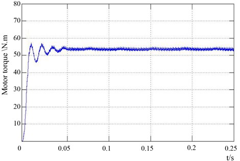
In Fig. 11, the torque of the induction motor starting process is detected and the waveform is displayed. The induction motor quickly completed the start, in 0.05 seconds into a stable state. After pre-excitation, the starting torque response is very fast, and the overshoot and fluctuation are very small.
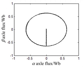
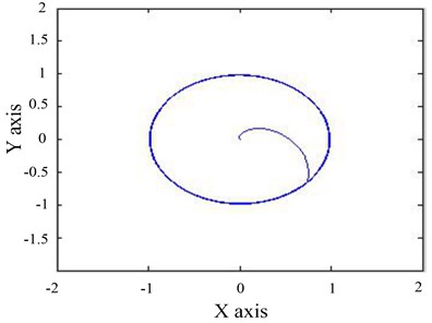
The flux linkage of induction motor is obtained by detecting the voltage and current output of the motor and calculating the motor model, shown in Fig. 12. It can be seen that the flux linkage fluctuation is very small in the process of pre-excitation start-up, and it quickly enters the steady state, which reduces the overshoot and oscillation. The trajectory of the magnetic linkage tends to be circular.
Fig. 12Motor flux linkage
6. Conclusions
In this paper, combined with the advantages and disadvantages of conventional starting mode of motor, the necessity of pre-excitation starting method for high-power motor is expounded. The main reason of induction motor overcurrent and the basic principle of DC pre-excitation are analyzed. A DC excitation pre-excitation method based on flux linkage compensation bias decoupling is adopted. Based on the theory of flux compensation and deviation decoupling, the excitation current and torque current are set by DC pre-excitation control, which realizes the stability of flux linkage amplitude and the dynamic decoupling of excitation subsystem and torque subsystem. The experimental results show that the stator current rises smoothly in the experimental process, and the starting peak current is suppressed obviously, and the torque can respond quickly. In addition, this method has a certain practical significance to improve the control performance of high-power, high-voltage variable-frequency speed control system.
References
-
Kaiqi Z., Yi W., Dianguo X. A new strategy to improve electromagnetic starting torque for thyristor controlled induction motors. Proceedings-Chinese Society of Electrical Engineering, Vol. 24, Issue 3, 2004, p. 145-150.
-
Terzi B., Despalatovi M., Slutej A. Magnetization curve identification of vector-controlled induction motor at low-load conditions. Automatika, Vol. 53, Issue 3, 2012, p. 255-262.
-
Qi Q., Long C., Wu J., et al. Impacts of a medium voltage direct current link on the performance of electrical distribution networks. Applied Energy, Vol. 230, 2018, p. 175-188.
-
Wang L., Jatskevich J. Including magnetic saturation in voltage-behind-reactance induction machine model for EMTP-type solution. IEEE Transactions on Power Systems, Vol. 25, Issue 2, 2010, p. 975-987.
-
Zhang Y., Zhu J., Zhao Z., Xu W., Dorrell D. G. An improved direct torque control for three-level inverter-fed induction motor sensorless drive. IEEE Transactions on Power Electronics, Vol. 27, Issue 3, 2010, p. 1502-1513.
-
Davari S. A., Khaburi D. A., Kennel R. An improved FCS-MPC algorithm for an induction motor with an imposed optimized weighting factor. IEEE Transactions on Power Electronics, Vol. 27, Issue 3, 2011, p. 1540-1551.
-
Zhang Y., Yang H. Two-vector-based model predictive torque control without weighting factors for induction motor drives. IEEE Transactions on Power Electronics, Vol. 31, Issue 2, 2015, p. 1381-1390.
-
Reed D. M., Hofmann H. F., Sun J. Offline identification of induction machine parameters with core loss estimation using the stator current locus. IEEE Transactions on Energy Conversion, Vol. 31, Issue 4, 2016, p. 1549-1558.
-
Bai H., Zhao Z. M., Hu X., Chen X. The experimental analysis of DC pre-excitation for 3-level inverter-motor system. Zhongguo Dianji Gongcheng Xuebao (Proceedings of the Chinese Society of Electrical Engineering), Vol. 26, Issue 3, 2006, p. 159-163.
-
Chen W., Xu D., Yang R., Yu Y., Xu Z. A novel stator voltage oriented V/F control method capable of high output torque at low speed. International Conference on Power Electronics and Drive Systems (PEDS), 2009, p. 228-233.
-
Zhengming B. H. Z. Research on starting strategies in the three-level high voltage high power inverters. Transactions of China Electrotechnical Society, Vol. 22, Issue 11, 2007, p. 91-97.
-
Zhang Y., Yang H. Model predictive flux control for induction motor drive. Proceedings of the CSEE, Vol. 35, Issue 3, 2015, p. 719-726.
-
Liying Q., Chenchen W., Minglei Z., Jian W. A decoupling current control scheme for induction machine controllers. Transactions of China Electrotechnical Society, Vol. 29, Issue 5, 2014, p. 174-180.
-
Hu S., Zhao Z., Yuan L., Wang X. DC pre-excitation start strategy based on the flux control for V/F controlled induction motor drive system. Diangong Jishu Xuebao (Transactions of China Electrotechnical Society), Vol. 27, Issue 7, 2012, p. 118-123.
-
Yan L., Dou M., Hua Z., Zhang H., Yang J. Optimal duty cycle model predictive current control of high-altitude ventilator induction motor with extended minimum stator current operation. IEEE Transactions on Power Electronics, Vol. 33, Issue 8, 2017, p. 7240-7251.
-
Holakooie M. H., Ojaghi M., Taheri A. Direct torque control of six-phase induction motor with a novel MRAS-based stator resistance estimator. IEEE Transactions on Industrial Electronics, Vol. 65, Issue 10, 2018, p. 7685-7696.
-
Rejeb O., Shittu S., Ghenai C., et al. Optimization and performance analysis of a solar concentrated photovoltaic-thermoelectric (CPV-TE) hybrid system. Renewable Energy, Vol. 152, Issue 6, 2020, p. 1342-1353.
-
Lee J. S., Lorenz R. D. Robustness analysis of deadbeat-direct torque and flux control for IPMSM drives. IEEE Transactions on Industrial Electronics, Vol. 63, Issue 5, 2016, p. 2775-2784.
-
Meng D., Xia Y., Xia Y. Engineering calculation of dynamic impedances and starting characteristics for high‐voltage induction motors. International Transactions on Electrical Energy Systems, Vol. 25, Issue 5, 2015, p. 920-932.
-
Zorgani Y. A., Koubaa Y., Boussak M. MRAS state estimator for speed sensorless ISFOC induction motor drives with Luenberger load torque estimation. ISA Transactions, Vol. 61, 2016, p. 308-317.
-
Zhengqi W., Xueliang H. Nonlinear decoupling control for bearingless induction motor based on support vector machines inversion. Transactions of China Electrotechnical Society, Vol. 30, Issue 10, 2015, p. 164-170.
-
Geng S., Hu A., Ma W., Li W., He N., Lu J. Vector control start-up mechanism of inductor motor and research of DC pre-excitation. Diangong Jishu Xuebao (Transactions of China Electrotechnical Society), Vol. 26, Issue 3, 2011, p. 29-35.
-
Hu Y., Xiao W., Cao W., Ji B., Morrow D. J. Three-port DC-DC converter for stand-alone photovoltaic systems. IEEE Transactions on Power Electronics, Vol. 30, Issue 6, 2014, p. 3068-3076.
-
Wu Y. E., Chiu P. N. A high-efficiency isolated-type three-port bidirectional DC/DC converter for photovoltaic systems. Energies, Vol. 10, Issue 4, 2017, p. 434.
About this article

This work is supported by the National Science Foundation of China (U1704157), National Key Research and Development Program of China (2017YFB0306400), Scientific and Technological Innovation Leaders in Central Plains (194200510012), Science and Technology Innovative Teams in University of Henan Province (18IRTSTHN011) and CSC Scholarship.
