Abstract
Intermittent motion mechanisms are widely used in semiautomatic and automatic machinery. Currently, the most common are mechanisms with a one-way coupling or mechanisms of variable structure. The intermittent movement in these mechanisms is provided by breaking the kinematic chain, so their use is undesirable in high-speed machines. The paper presents and analyzes kinematics of planetary transmission with elliptical gears, which performs intermittent motion of output link without interruption of kinematic chain. A kinematic model of the mechanism is constructed, and there are obtained equations for determining the velocity analogue of the output link of the planetary gear. An experimental verification of the adequacy of the developed mathematical model was carried out on the example of studying the position function of the mechanism. The measurement errors were estimated using statistical methods. Using the chi-squared test, the hypothesis of a normal distribution of measurement errors was verified, and confidence interval was determined.
Highlights
- The kinematic analysis of the intermittent motion planetary mechanism with elliptical gears is presented
- An experimental setup of the planetary gear is presented and the position function of the mechanism is measured
- The measurement errors were estimated using statistical methods, the hypothesis of their normal distribution was verified, and confidence interval was determined
1. Introduction
Intermittent motion mechanisms are widely used in mechanical engineering [1-6]. The most widespread practical application they received in semiautomatic and automatic machinery, instruments, watches, projectors, ordinance machine tools, as well as in printing, packaging, transfer lines, etc. [1, 2].
Intermittent motion mechanisms allow having specified duration stops of output link at continuous motion of the input link. Currently, the most studied and common are two types of mechanisms:
– mechanisms of a permanent structure with a one-way coupling (anchor mechanisms, ratchets);
– variable structure mechanisms (Geneva drives, star wheels, mutilated gears).
Today the Geneva drives is extensively used in automatic machinery (the tool changers in CNC machines; the turrets of turret lathes, screw machines, and turret drills; some kinds of indexing heads and rotary tables; and so on) or conveyors [7, 8]. In order to reduce shockloading, a basic Geneva mechanism in combination with linkages, gears, and cams is applied as shown in [9]. Another method to improve the dynamic performance and kinematic characteristics of the mechanism is using curved slots as reported in [10, 11].
The intermittent movement in these mechanisms is provided by breaking the kinematic chain, so their use is undesirable in high-speed machines, due to shocks arising at the beginning and end of the movement phase [12]. Thus, there is an actual task to develop and study mechanisms with intermittent movement of the output link, which is carried out without breaking of the kinematic chain.
Recently, a large number of scientific papers have been published on the practical application of mechanisms with non-circular gear wheels [13]. This type of gear implements various types of movement of the working bodies and is widely used in a variety of mechanical systems.
For example, there are proposed: variable-ratio chain drives with noncircular sprockets for bicycles [14]; a mechanism incorporating a Geneva wheel and a gear train to achieve intermittent motion [15]; the gear drives with non-circular gears applied for speed variation and generation of functions [16]; planetary gears with non-circular wheels as a part of rotor hydraulic machines [17]; a knee motion assist mechanism for wearable robot with non-circular gear and grooved cams [18]; a planetary gear train with non-circular gears for high performance bicycles [19]. Non-circular gears are also used to reduce speed and torque fluctuations in rotating shafts [20], to balance shaking moments in spatial linkages [21].
The various use of non-circular gears is explained by the large progresses made in their design and manufacture. Significant successes in this area are described in the papers [13, 22-24] of scientists from Wuhan University of Technology, who presented various schemes of planetary mechanisms with non-circular wheels and technologies for their manufacture. There are developed mechanisms with external, internal gearing, as well as bevel gears with non-circular wheels [13]. Based on the theory of screws, a study was carried out to investigate the generation of noncircular bevel gear with free-form tooth profile and curvilinear tooth lengthwise [23].There are developed methods for the formation of gears and predicting the cutting force of a rack with a variable gear ratio, including novel discrete algorithms of contact length and chip area [24].
Thus, non-circular planetary gears are one of the most promising mechanisms for converting the rotational motion of the input shaft into the desired type of motion of the output shaft. Therefore, their theoretical and experimental studies are relevant and can be used in the design, manufacture and practical application in industry [25, 26].
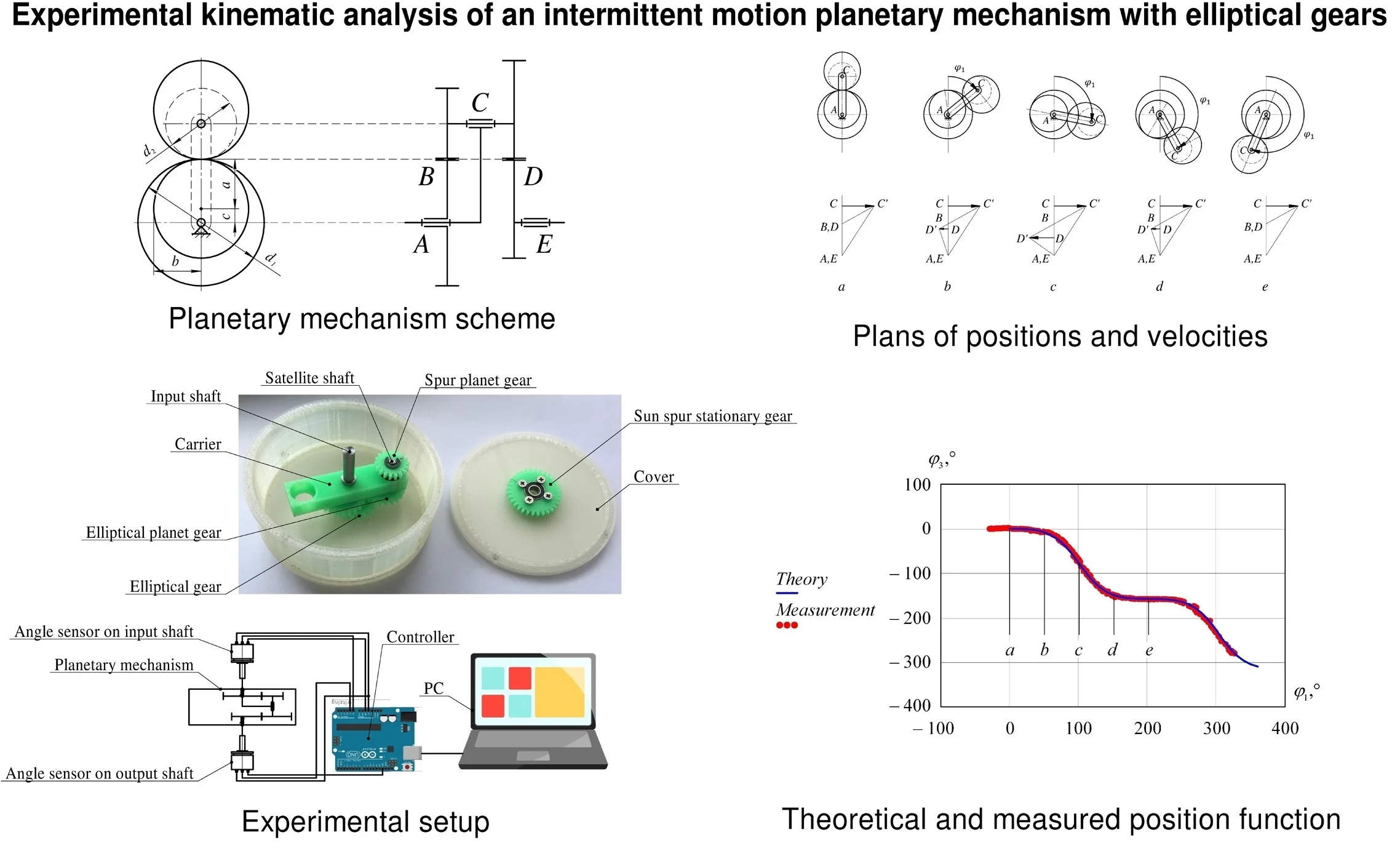
The object of research in this article is a two-row planetary gear transmission with two external gears, including a pair of cylindrical gears and a pair of elliptical gears (Fig. 1), which is presented in [27].
Fig. 1Design of the intermittent motion planetary mechanism: 0 – cover, 1 – input shaft, 2 – carrier, 3 – output shaft, 4 – sun spur stationary gear, 5 – elliptical gear, 6 – spur planet gear, 7 – elliptical planet gear, 8 – satellite shaft
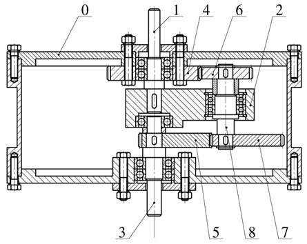
Planetary transmission (Fig. 1) operates as follows. The input shaft 1 performs rotational movement, which is translated to the carrier 2, thereby the spur gear 6 rotates around a stationary gearwheel 4. The rotational motion of the spur gear 6 transmitted to the satellite shaft 8 and the elliptical gear 7 which drives the elliptical gear 5 and the output shaft 3 respectively. At moment when the gear ratio of elliptical gears pair is equal to the ratio of cylindrical gears pair, the output shaft 3 is stopped. Further, the angular velocity of output shaft increases to a maximum value and then decreases again to zero. This provides the intermittent motion of the output shaft.
The aim of the paper is theoretical and experimental kinematic study of the proposed planetary mechanism with elliptical gears.
2. Kinematic model of planetary mechanism
The proposed mechanism is characterized by the following main parameters: radius of the sun spur gear, radius of the satellite spur gear, semi-major axis , minor axis , eccentricity and focal distance of elliptical gears (Fig. 2).
Fig. 2Scheme of the intermittent motion planetary mechanism
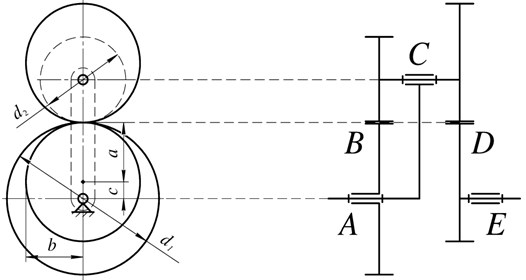
As can be seen from Fig. 2, to ensure intermittent motion of the output link, the dimensions of the cylindrical and elliptical gears are related by the following equations:
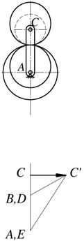
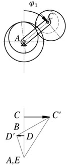
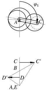
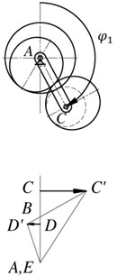
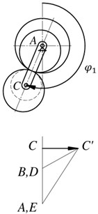
To conduct a kinematic analysis of the proposed mechanism, there is constructed positions and linear velocities plans of mechanism links (Fig. 3) [26, 28]. Intermittent motion of the output link in this case is achieved by the fact that point D on the velocity plan will not intersect the zero line.
Fig. 3Plans of positions and linear velocities of the mechanism links
a)
b)
c)
d)
e)
The vector CC' from the point C lying at the same level as the point C in the mechanism scheme shows the velocity of the carrier point C. Connecting the point C' with the point A, which corresponds to the stationary point A on the axis of the carrier, gives a line C'A showing distribution of the carrier CA linear velocity. For a satellite, there are known the velocities of two points: the point C, which is common for a satellite and a carrier, and the point B, the velocity of which is equal to zero in accordance with the condition of rolling of the initial circle of a gear 6 on the initial circle of a gear 4. Point B matches with the point B with the velocity plan. Connecting point C' with point B gives the linear velocity distribution line for a satellite. The velocity of point D is shown by the vector DD', while point D' lies on the line BC'. This point is common for the elliptical gears 5 and 7. Consequently, connecting point D' with point A gives the distribution line of linear velocity of an elliptical gear 5 and, thus, that of a output shaft 3. At the moment when the gear ratio of the pair of elliptical wheels is equal to the gear ratio of the pair of cylindrical wheels, the output shaft 3 is stationary (position ). Then the velocity of the output shaft increases (position ) and reaches its maximum value (position ), then again decreases (position ) to zero (position ). This way provides intermittent movement with stops of the output link.
An analogue of the angular velocity of the output link 3, according to Fig. 3, will be determined as:
where and are angular velocities of input and output shafts, respectively; and are linear velocities of points D and C; BD, BC, AC and DE are lengths of the segments in Fig. 3.
The distances AC and BC in Eq. (3) are determined as:
To determine the segments BD and DE, it is necessary to find the length of the segment CD. It is determined by the equation of the centroid of an elliptical wheel [29, 30]:
where is the angle of rotation of the elliptical wheel 7.
Then, according to Fig. 3, the segments BD and DE are defined as:
By substituting Eqs. (4-8) in Eq. (3), the equation for determining the analogue of the output shaft angular velocity is obtained:
Thus, by integrating Eq. (9) over the generalized coordinate , the function of the mechanism output link angle of rotation can be obtained.
3. Experimental analysis of the output link position function
Using the study of the position function , we verify the adequacy of the developed kinematic model to a real mechanism. For further research, a prototype of the planetary gear was designed and manufactured from ABS plastic using additive technologies (Fig. 4).
The rotation angle is measured using absolute encoders mounted on the input and output shafts of the mechanism (Fig. 5). The signal from the sensors is processed using the controller, which performs the function of an analog-to-digital converter, and then transmitted to a personal computer. Further, the obtained data can be easily processed in any computer mathematics system, for example, MathCAD.
Fig. 4Prototype of the planetary intermittent motion mechanism: 0 – cover, 1 – input shaft, 2 – carrier, 3 – output shaft, 4 – sun spur stationary gear, 5 – elliptical gear, 6 – spur planet gear, 7 – elliptical planet gear, 8 – satellite shaft
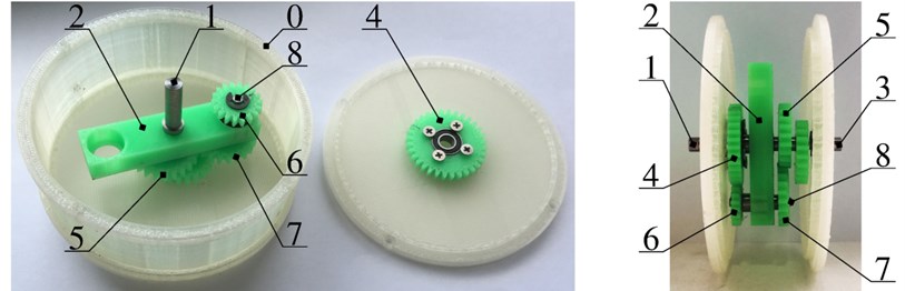
Fig. 5Experimental setup: 0 – cover, 1 – input shaft, 2 – carrier, 3 – output shaft, 4 – sun spur stationary gear, 5 – elliptical gear, 6 – spur planet gear, 7 – elliptical planet gear, 8 – satellite shaft, 9, 10 – angle sensors, 11 – controller, 12 – PC

Brief specifications of the experimental setup are presented in Table 1.
Table 1Geometrical and electrical characteristics of the experimental setup
Geometrical parameters of the mechanism | |||||||||
, mm | , mm | , mm | , mm | , mm | |||||
16 | 9 | 12.5 | 12 | 3.5 | 0.28 | ||||
Parameters of angle sensor | |||||||||
Resolution | Linearity | Update speed | Output signal | Outside diameter | |||||
360° / 4096 ≈ 0.088° | 0.3 % | 0.6 ms | 0-5 V | 22 mm | |||||
The study of the position function was carried out by measuring the rotation angles of the input and output shafts of the planetary mechanism. The theoretical position function and the results of the measurements are shown in Fig. 6.
Designations , , , and in Fig. 6 correspond to the positions in Fig. 3. Kinematic analysis showed that the output link is stopped every 202.5° of the input link rotation. Fig. 6 shows that the kinematics of the mechanism is described correctly, and the maximum deviations of the experimental results from theoretical data did not exceed 5 %.
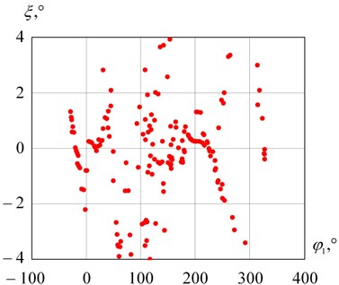
To perform a complete analysis of the experimental data, it is necessary to conduct a statistical analysis of the measurement results. Fig. 7 shows graphs of the absolute errors of the experimental results.
Fig. 6Theoretical position function and measurements
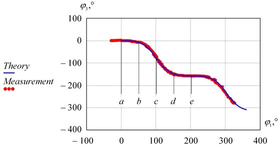
Fig. 7Absolute measurement errors
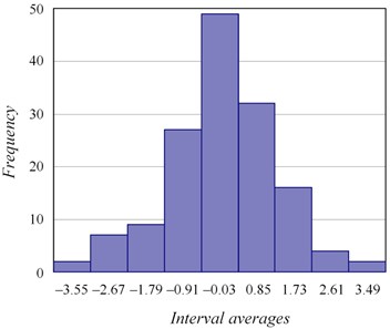
Let us construct an interval variational series of the obtained experimental data. The optimal number of intervals was assessed using Sturges’ rule [31, 32]:
where is the size of the experimental data ( 148).
Dividing the sample into 9 intervals according to Eq. (10), a histogram of dispersion of the measurement results was constructed (Fig. 8).
Fig. 8Histogram of measurement errors
Further, it is necessary to verify the hypothesis of the normal distribution of the studied sample. The parameters of the normal distribution [33, 34] (mathematical expectation and standard deviation ) are determined by the following equations:
where is the average value of the interval, is the probability that the value falls into the interval.
For the studied sample and . The theoretical probabilities of falling into the interval were calculated through the integral function:
where is the integral function of the selected distribution law (in our case, the law of normal distribution).
Theoretical interval frequencies are determined by the following equation:
Histograms of empirical and theoretical frequencies are plotted on the same graph (Fig. 9) and allow to compare the results.
Fig. 9Histograms of empirical and theoretical frequencies
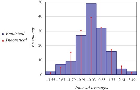
Fig. 9 shows that the empirical and theoretical frequencies have close values. To test the hypothesis of a normal distribution, the Pearson’s criterion [35, 36] is used:
The correspondence of the obtained value to the selected hypothesis about the normal distribution was checked by the significance level and the number of degrees of freedom . Since , then the selected hypothesis is considered true.
The percentage of probability that the distribution belongs to normal can be expressed as [37]:
where is the gamma function, is the number of degrees of freedom.
Using Eq. (16), we obtain 26.93. Thus, this distribution is normal with the significance level 26.93 %.
Further, we determine the measurement error with a confidence probability of 0.99. The quantile of distribution is determined from the following equation:
where is the Laplace function.
Since the Laplace function is odd, therefore . Transforming the Eq. (17), we obtain:
Using the table of values of [38], we find 2.57. Then the confidence interval with a reliability of 0.99 is written in the form:
Thus, the errors of the performed position function measurements with a probability of 0.99 fall into the interval 0.027°±3.33°.
4. Conclusions
The paper presented kinematics of the two-row planetary gear transmission with two external gears, including a pair of cylindrical gears and a pair of elliptical gears, which performs the intermittent motion. Plans of positions and velocities were constructed, as a result of kinematic analysis, there was obtained equation to determine the angular velocity analogue of the mechanism output link.
The conducted experimental studies confirmed the adequacy of the constructed kinematic model to the real mechanism. The statistical analysis showed:
– maximum deviations of the measurement results do not exceed 5 %;
– the distribution of measurement errors corresponds to the normal law;
– errors of the obtained measurements with a probability of 0.99 lie in the confidence interval 0.027°±3.33°.
Thus, the obtained kinematic characteristics can be used in further dynamic, force analysis, as well as in the design of intermittent motion mechanisms with proposed planetary gear.
References
-
Sclater N., Chironis N. P. Mechanisms and Mechanical Devices Sourcebook. McGraw-Hill, New York, 2001.
-
Bickford J. H. Mechanisms for Intermittent Motion. Industrial Press Inc., New York, 1972.
-
Chang Z., Xu C., Pan T., Wang L., Zhang X. A general framework for geometry design of indexing cam mechanism. Mechanism and Machine Theory, Vol. 44, 2009, p. 2079-2084.
-
Zakharenkov N. V., Konovalov V. E., Kvasov I. N., Bigushev S. M. Increasing operation capacity for spherical bearing of indexing spatial mechanism under load. Journal of Physics: Conference Series, Vol. 1260, Issue 11, 2019, p. 112037.
-
Kim J.-W., Lee S., Seo T., Kim J. A new non-servo motor type automatic tool changing mechanism based on rotational transmission with dual four-bar linkages. Meccanica, Vol. 53, Issue 9, 2018, p. 2447-2459.
-
Yang Y., Wang J., Zhou S., Huang T. Design of a novel coaxial eccentric indexing cam mechanism. Mechanism and Machine Theory, Vol. 132, 2019, p. 1-12.
-
Lin W. Y., Tsai Y. H., Hsiao K. M. Optimum variable input speed for kinematic performance of Geneva mechanisms using teaching-learning-based optimization algorithm. Proceedings of the Institution of Mechanical Engineers, Part C: Journal of Mechanical Engineering Science, Vol. 231, Issue 10, 2017, p. 1871-1883.
-
Lin W. Y., Tsai Y. H., Hsiao K. M. A new indexing motion program for optimum designs of Geneva mechanisms with curved slots. Proceedings of the Institution of Mechanical Engineers, Part C: Journal of Mechanical Engineering Science, Vol. 231, Issue 21, 2017, p. 3974-3986.
-
Sujan V. A., Meggiolaro M. A. Dynamic optimization of Geneva mechanisms. Proceedings of the International Conference on Gearing, Transmissions and Mechanical Systems, London, 2000, p. 687-696.
-
Figliolini G., Rea P., Angeles J. The pure-rolling cam-equivalent of the Geneva mechanism. Mechanism and Machine Theory, Vol. 41, 2006, p. 1320-1335.
-
Lee J.-J., Jan B.-H. Design of Geneva mechanisms with curved slots for non-undercutting manufacturing. Mechanism and Machine Theory, Vol. 44, 2009, p. 1192-1200.
-
Kozhevnikov S. N., Esipenko Y. I., Raskin Y. M. Elements of Mechanisms. Moscow, 1956.
-
Zheng F., Hua L., Han X., Li B., Chen D. Synthesis of indexing mechanisms with non-circular gears. Mechanism and Machine Theory, Vol. 105, 2016, p. 108-128.
-
Freudenstein F., Chen C. K. Variable-ratio chain drives with noncircular sprockets and minimum slack-theory and application. Journal of Mechanical Design, Vol. 113, Issue 3, 1991, p. 253-262.
-
Dooner D. B., Palermo A., Mundo D. An intermittent motion mechanism incorporating a Geneva wheel and a gear train. Transactions of the Canadian Society for Mechanical Engineering, Vol. 38, Issue 3, 2014, p. 359-372.
-
Litvin F. L., Gonzalez Perez I., Fuentes A., Hayasaka K. Design and investigation of gear drives with non-circular gears applied for speed variation and generation of functions. Computer Methods in Applied Mechanics and Engineering, Vol. 197, 2008, p. 3783-3802.
-
An I.-K. Synthesis, Geometric and Strength Calculations of Rotor Hydromachines Planetary Mechanisms with Non-Circular Gears. Ph.D. Thesis, Tomsk, 2001.
-
Terada H., Zhu Y., Suzuki M., Cheng C., Takahashi R. Developments of a knee motion assist mechanism for wearable robot with a non-circular gear and grooved cams. Mechanisms and Machine Science, Vol. 3, 2012, p. 69-76.
-
Mundo D. Geometric design of a planetary gear train with non-circular gears. Mechanism and Machine Theory, Vol. 41, 2006, p. 456-472.
-
Dooner D. B. Use of noncircular gears to reduce torque and speed fluctuations in rotating shafts. Journal of Mechanical Design, Vol. 119, Issue 2, 1997, p. 299-306.
-
Han J. Y. Complete balancing of the shaking moment in spatial linkages by adding planar noncircular gears. Archive of Applied Mechanics, Vol. 67, Issues 1-2, 1997, p. 44-49.
-
Zheng F., Hua L., Han X., Li B., Chen D. Linkage model and manufacturing process of shaping non-circular gears. Mechanism and Machine Theory, Vol. 96, 2016, p. 192-212.
-
Zheng F., Hua L., Han X., Chen D. Generation of noncircular bevel gears with free-form tooth profile and curvilinear tooth lengthwise. Journal of Mechanical Design, Vol. 138, Issue 6, 2016, p. 064501.
-
Xu M., Han X., Hua L., Zheng F. Modeling and methods for gear shaping process and cutting force prediction of variable transmission ratio rack. International Journal of Mechanical Sciences, Vol. 171, 2020, p. 105364.
-
Prikhod’ko A. A., Smelyagin A. I. Investigation of power consumption in a mixing device with swinging movement of the actuating element. Chemical and Petroleum Engineering, Vol. 54, Issues 3-4, 2018, p. 150-155.
-
Prikhodko A. A., Smelyagin A. I. Dynamics of rotationally reciprocating stirred tank with planetary actuator. Journal of Physics: Conference Series, Vol. 858, 2017, p. 012026.
-
Prikhodko A. A., Smelyagin A. I., Tsybin A. D. Kinematics of planetary mechanisms with intermittent motion. Procedia Engineering, Vol. 206, 2017, p. 380-385.
-
Prikhodko A. A. Structural and kinematic analysis of a stirred tank planetary drive. Matec Web of Conferences, Vol. 226, 2018, p. 01012.
-
Coxeter H. S. M. Introduction to Geometry. Wiley, New York, 1969.
-
Litvin F. L., Fuentes A. Gear Geometry and Applied Theory. Cambridge University Press, 2004.
-
Scott D. W. Sturges’ rule. Wiley Interdisciplinary Reviews: Computational Statistics, Vol. 1, Issue 3, 2009, p. 303-306.
-
Saha P., Roy R., Sarkar A. K., Pal M. Preferred time headway of drivers on two-lane highways with heterogeneous traffic. Transportation Letters, Vol. 11, Issue 4, 2019, p. 200-207.
-
Mohammed M. B., Adam M. B., Ali N., Zulkafli H. S. Improved frequency table’s measures of skewness and kurtosis with application to weather data. Communications in Statistics-Theory and Methods, 2020, https://doi.org/10.1080/03610926.2020.1752386.
-
Omran H., Alahmadi H., Salama K. N. Matching properties of femtofarad and sub-femtofarad MOM capacitors. IEEE Transactions on Circuits and Systems I: Regular Papers, Vol. 63, Issue 6, 2016, p. 763-772.
-
Cochran W. G. The χ2 test of goodness of fit. The Annals of Mathematical Statistics, Vol. 23, Issue 3, 1952, p. 315-345.
-
Nisen J. A., Schwertman N. C. A simple method of computing the sample size for Chi-square test for the equality of multinomial distributions. Computational Statistics and Data Analysis, Vol. 52, Issue 11, 2008, p. 4903-4908.
-
Prikhodko A. A., Smelyagin A. I., Mevsha N. V. An experimental study of kinematics of a planetary rotationally reciprocating stirring tank. University proceedings. Volga region, Issue 3, p. 121-133.
-
L'vovskij E. N. Statistical Methods for Constructing Empirical Formulas. Higher School, Moscow, 1982.
About this article

The reported study was funded by scholarship of the president of the Russian Federation according to the research project SP-2763.2019.1.
