Abstract
Many methods are available to analyze the process of the travelling-wave propagation. Among these methods, the Finite Difference Time Domain (FDTD) method has a distinct advantage in calculating dynamic process of the travelling wave propagation in the time domain and is thus applied to the field of power system protection for researching transient fault induced travelling-wave propagation. The novelty of this paper is that the attenuation law of the traveling wave signal affected by the fork junction in the multi-branch distribution network is summarized and the cause of failure in the fault location based on the incipient travelling wave front method in distribution networks is found.
1. Introduction
The earth fault particularly transient fault occurs frequently in distribution networks. This fault severely affects the service quality of the power supply and the reclosure is one of the effective measures taken to reduce the losses bringing about by this fault. With the rapid development of the Ubiquitous Internet of Things in Electricity, the location of transient fault is more and more concerned to improve the maintenance ability for distribution networks. However, transient fault is hard to be located due to the attenuation of the travelling wave induced by this fault particularly in multi-branch distribution networks. In order to understand the reason that the travelling wave is attenuated, a clear dynamic process of this travelling wave propagation is needed urgently.
Many methods are available to calculating the process of the travelling-wave propagation, such as, BLT equation based method and FDTD method. Among these methods the FDTD method has a distinct advantage in fast calculation of this dynamic propagation due to the direct calculation in the time domain compared with BLT equation based method. Due to the high performance in fast calculation the FDTD method is gradually applied to the field of power system protection for researching the travelling-wave propagation induced by transient faults such as lightning or vegetation-related failures. The lightning surges on a distribution line are analyzed effectively by the FDTD method as in [1, 2]. However, the analysis on the attenuation of travelling-wave affected by the fork junction of multi-branch networks based on the FDTD method has not been found in published articles.
In general, series resistive elements result in the attenuation of the travelling-wave and parallel capacitive elements result in the suppression of the incipient wavefront. In terms of signal transmission problems in networks with constraints, a hybrid evolutionary approach is proposed in [3] which is time-consuming for the large number of particles. As a result, this approach is hard to be used for online location. While travelling-wave based location method has been widely applied in high voltage transmission line for online fault location. However, the technological problems on the application of the traveling-wave based method in distribution networks still to be further resolved. Some related experiments for multi-branch networks as in [4] indicated that the characteristic of the actual travelling-wave attenuation is inconsistent with the theoretical damping characteristic related to resistive and capacitive elements. The effect of fork junction of multi-branch networks is thus concerned gradually to further discuss the characteristic of the travelling-wave propagation as in [5-7].
This paper derived the telegraph equations of the multi-branch distribution network in difference expression and these equation boundary conditions were determined in Section 2. In order to verify that this method is feasible and efficient in analyzing the attenuation of transient fault induced travelling-wave in multi-branch networks, the parameters of this network were configured and the expected simulation results were obtained in Section 3, followed by the conclusions.
2. FDTD method
2.1. Derivation of the difference equations for two parallel transmission lines
Two parallel transmission lines are modeled by a corresponding equivalent circuit in distributed parameters form in the time domain as shown in Fig. 1. This figure shows that the current flowing along the transmission line is a function of time and location and also the voltage between the two transmission lines has a similar function. In Fig. 1 and are the step of time and longitudinal spatial sampling interval respectively.
Fig. 1The equivalent circuit of two parallel transmission lines with distributed parameters in the time domain where r, l, g and c are resistance, inductance, conductance and capacitance per length respectively
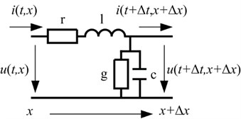
It can be seen from the Fig. 1 that the telegraph equations are given by Eq. (1) according to the Kirchhoff’s law:
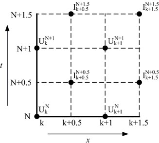
In order to build difference expressions related to Eq. (1) the mesh is generated by dividing the area that consists of time and longitudinal length into unit squares that consists of and . The part of this mesh is shown in Fig. 2.
The corresponding difference expressions are thus obtained:
where the coefficients are respectively calculated by:
Fig. 2Mesh generation in a range of the time interval from N to N+ 1.5 and the longitudinal spatial interval from k to k+ 1.5
2.2. Determination of boundary conditions
The multi-branch distribution network has one or more fork junctions besides terminal junctions. Fig. 3 shows a fork junction which connects three groups of two parallel transmission lines where one transmission line in each group as a reference line is omitted. It is assumed that these three groups of transmission lines in Fig. 3 have a common reference line.
Fig. 3A fork type junction which connects three groups of two parallel transmission lines
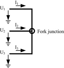
According to Kirchhoff’s law, the current relationship between these three transmission lines shown in Fig. 3 is expressed by:
The voltage relationship between these three transmission lines is expressed by Eq. (5) due to these lines having a common junction:
Finally, the boundary condition in difference form for the fork junction of the multi-branch network is given by Eq. (6) assuming that all lines have the same type:
where denotes the voltage of the observation point located at the end of the transmission line with number of 1 at the time of and that is a value for transition between lines with number of 1, 2 and 3 in order to iterate the voltage, . The other voltages and currents in Eq. (6) have similar representations to .
Similarly, the boundary conditions in difference form for the open-circuit and short-circuit terminals of this transmission line are given.
Open-circuit:
Short-circuit:
3. Simulation results
A reduced-scale branch network that consists of one fork junction and three lines is built in Fig. 4.
Fig. 4A reduced-scale branch network that consists of one fork junction, Jb, and three lines of L1, L2 and L3 where the transient fault represented by Gaussian pulse occurs at the distance of Lf form the source terminal, Js
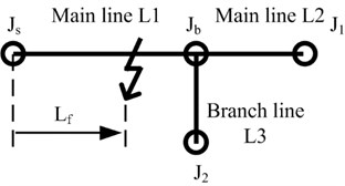
Simulation parameters are configured that is 0.1 ns; is 0.1 m, and the total number of is 10500. The total length of main line L1, main line L2, and branch line L3 are 100.1 m, 50.1 m, and 30.1 m respectively. The distance of between fault location and the source terminal is 90 m and the amplitude of this fault represented by Gaussian pulse is 1.56 V. The dynamic process of travelling-wave propagation is shown in Fig. 5.
It can be seen clearly from the Fig. 5 that the dual incipient wavefront propagates from the fault location to both terminals of the main line L1 after transient fault occurs. When the right wavefront arrives at the fork junction the reflection and transmission phenomena of this wave appear. After that negative reflective wave propagates back along the original line. At the same time this incipient wavefront is transmitted through the fork junction into both lines of L2 and L3 and at this time these transmitted travelling waves into lines of L2 and L3 become positive transmissive waves. The peak values of both the reflective wave and the transmissive wave are less than that of the transient wavefront. The waveform along the main line of L1 becomes more and more distorted due to the repeat reflection and transmission of travelling-wave in the junction over time.
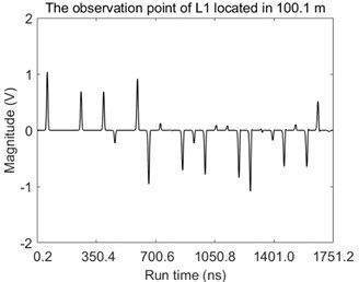
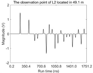
The magnitudes of voltage over the time at observation points are also given in Fig. 6.
It can be seen directly from the Fig. 6 that amounts of pulses are observed at each observation point and the peak values of these pulses fluctuate dramatically which easily results in the failure of fault location by using the travelling-wave method due to the inappropriate setting value or the unreliable synchronous measurement.
Fig. 5The travelling-wave propagation along three lines of L1, L2, and L3 at the time of: a) 36.7 ns, b) 58.4 ns, c) 80.1 ns, and d) 1751.2 ns
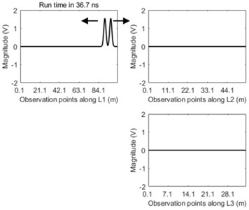
a)
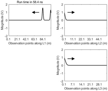
b)
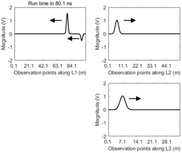
c)
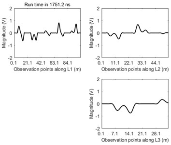
d)
Fig. 6The magnitudes of voltage over the time at the observation point located in: a) 100.1 m along the L1 and b) 49.1 m along the L2
a)
b)
4. Conclusions
The transient fault induced travelling-wave propagation for multi-branch distribution networks is analyzed based on FDTD method in this paper. The boundary conditions are derived and the validity of the FDTD method applied in multi-branch distribution network is verified. Some conclusions are summarized by:
1) The FDTD method is direct and effective to analyze the transient fault induced travelling-wave.
2) The fork junction decreases the peak values of the travelling-wave front even for lossless transmission line model and the decreased peak value is frequently a multiple of one-third of that of the original fault.
3) The fork junction has thus an effect on the travelling-wave based method and this case should not be neglected.
References
-
Chen H., Du Y., Yuan M., Liu Q. H. Lightning-induced voltages on a distribution line with surge arresters using a hybrid FDTD-SPICE method. IEEE Transactions on Power Delivery, Vol. 33, Issue 5, 2018, p. 2354-2363.
-
Natsui M., Ametani A., Mahseredjian J., Sekioka S.,Yamamoto K. FDTD analysis of nearby lightning surges flowing into a distribution line via groundings. IEEE Transactions on Electromagnetic Compatibility, Vol. 62, Issue 1, 2020, p. 144-154.
-
Chen T., Wang S., Tseng W. Using a hybrid evolutionary algorithm for solving signal transmission station location and allocation problem with different regional communication quality restriction. International Journal of Engineering and Technology Innovation, Vol. 10, Issue 3, 2020, p. 165-178.
-
Wang C., Wu N., Fan S. Fault location in multi-branch distribution network based on the first traveling wave time difference of arrival relationship. Chinese Automation Congress (CAC), Hangzhou, China, 2019, p. 4443-4450.
-
Wang K., Wang J., Chang C., Zhang J., Jia L.,Zhao J. A fault location method for multi-branch distribution lines. 14th International Conference on Natural Computation. Fuzzy Systems and Knowledge Discovery (ICNC-FSKD), Huangshan, China, 2018, p. 1056-1060.
-
Feng G., Xu M., Chen X., Zeng X., Wang P., Zhuo C. Design and experimental study of traveling wave positioning system based on TMR. 3rd Conference on Energy Internet and Energy System Integration (EI2), Changsha, China, 2019, p. 1150-1154.
-
Zhang K., Zhu Y., Liu X. A fault locating method for multi-branch hybrid transmission lines in wind farm based on redundancy parameter estimation. Journal of Modern Power Systems and Clean Energy, Vol. 7, Issue 5, 2019, p. 1033-1043.
About this article

The authors would like to express their thanks for simulation experiment which were conducted in Hunan Province Key Laboratory of Smart Grids Operation and Control (Changsha University of Science and Technology), Changsha, as part of a research project on National Key R&D Program of China 2017YFB0902903.
