Abstract
Wind turbine mainly relies on blades to capture wind energy and complete energy conversion. Wind turbine blade is one of the key components of wind turbine. In the full scale load test of wind turbine blade, the moment matching is the key part of the test and the premise of wind turbine blade certification. In order to solve the matching problem of the bending moment and the arrangement of counterweight in the fatigue loading test, an improved intelligent optimization algorithm was proposed to achieve the purpose of moment matching. The relationship between the excitation frequency of the rotating mass and the natural frequency of the blade was determined through the identification of the modal test parameters, and the calculation model of the section bending moment was constructed. Based on the optimization algorithm, the joint optimization of moment distribution and amplitude control was carried out with the mean square error as the fitness function. The correctness and feasibility of the balance weight optimization scheme for moment matching in uniaxial fatigue test were verified through the blade test.
1. Introduction
Fatigue loading test is a very important part in the design and testing of wind turbine blades. Its purpose is to check whether the blade structure, layering and bonding design are reasonable, and whether the blade can reach the design life under the cycle action of test load, to ensure the blade can withstand loads throughout the life cycle of service [1, 2]. The uniaxial resonance fatigue loading test of wind turbine blades driven by a rotating mass has the advantages of less hardware and simple control, and is the main implementation method of wind turbine blade fatigue loading tests. Although the biaxial fatigue loading test can effectively shorten the test period, there is little research on the development of the optimization algorithm for the bending moment matching of the wind turbine blade full-size loading test, and the algorithm is not further optimized. It is difficult to ensure the application effect of the algorithm. The blade test manufacturer only obtains the additional masses scheme for the bending moment matching of the fatigue loading test of the wind turbine blade through experience or simple calculation. The obtained fatigue test data is not accurate, which has caused the distortion of the fatigue load test results to a certain extent.
At present, the research on bending moment matching of uniaxial fatigue loading test of wind turbine blade has attracted more and more attention from scholars at home and abroad. Usually, a single point excitation is applied at about 70 % of the blade span to resonate the blade to ensure the bending moment matching error of each section control within 7 %. Liao et al. Proposed formulating a bending moment spectrum to predict the location of maximum fatigue damage [3]. Huang et al. conducted a single point and single axis constant-amplitude load test of a 1 MW DF64A wind turbine blade, and used fatigue damage theory to obtain the static load and dynamic load parameters at the fatigue load design point, including the position and the weight of additional masses, excitation force, working radius of rotating excitation device and motor parameters [4]. Shi et al. concluded that different loading methods and the temperature and humidity of the surrounding environment will affect the test results. When formulating the test plan, comprehensive consideration should be taken according to the specific situation [5]. Li et al. used MATLAB/Simulink software to establish a simulation model, and obtained the amplitude amplification curve of the blade vibration at different frequency ratios, and concluded that the loading frequency during the wind turbine fatigue test should be consistent with the first-order natural frequency of the blade. When the vibration is stable, the amplitude is the largest, the test period is the shortest, and the loading efficiency is the highest [6]. Based on the cumulative fatigue damage theory and Markov frequency matrix method, Wu Jianzhong designed a real-time damage assessment system for wind turbine blade fatigue loading test. This system can realize real-time processing of test data and has the same accuracy as the data post-processing method [7]. Xu et al. established a non-linear three-dimensional finite element model of the blade composite material structure. According to the requirements of the GL code, four limit loads were applied to the blade finite element model to analyze the blade strain and safety factor distribution and nonlinear buckling stability [8]. Jin et al. conducted modal analysis and static analysis of wind power blades, and showed that the results of the first-order natural frequency in flap-wise and edge-wise direction and the displacement analysis under the two load conditions are basically consistent with the measured results [9]. Xue et al. described the structural configuration and load of blades, and described the use of Fiber SIM, CATIA and finite element software to model the finite element of composite wind turbine blades, and carried out structural stability analysis [10]. As a very effective optimization method, the global intelligent optimization algorithm is now increasingly used in engineering practice [11]. Lee et al. calculated the required driving force at each excitation location candidate based on the damping ratio equation, and the masses distribution scheme with the required minimum driving force near the point where the bending moment matching error is minimum [4]. The Institute of Engineering Thermophysics, Chinese Academy of Sciences proposed a combination of wind turbine blade finite element model and global optimization particle swarm optimization algorithm, and further used dynamic analysis to obtain the fatigue test equivalent additional mass optimization scheme [12]. Greaves et al. controlled the distribution of test bending moments by adding additional mass to the test blades, and optimized the location and weight of the additional mass based on genetic algorithm, to reduce the test and target bending moment distribution errors [13, 14]. The Scholars at home and abroad have studied the optimization of bending moment matching for uniaxial fatigue loading test of wind power blades. The mathematical calculation process is complicated, and the research content focuses on the characteristics of a single blade. At the same time, it is difficult to ensure the application effect of the algorithm without improving the design of high-performance optimization algorithms. Particle Swarm Optimization (PSO) algorithm is a nature-inspired method that has been utilized as a powerful optimization tool in a wide range of applications since its inception in 1995 [15]. Michał used genetic algorithms as optimization technique and fuzzy assessment system to manage the power units maintenance schedules [16].
The purpose of this paper is to study the hybrid intelligent optimization algorithm to simplify the mathematical calculation, and to design a universal method of moment matching counterweight placement for wind turbine blade uniaxial fatigue loading test, rather than only for a single blade, so that the research results have robustness and generalization ability.
2. Fatigue parameter identification and model construction
The problem of bending moment matching of the uniaxial fatigue loading test driven by the rotating mass, that is how to arrange the counterweight and vibration device installed on the blade. The determination of the rotation frequency of the rotating mass of the vibration excitation device and the calculation method of the bending moment along blade span section are the premise and basis for the design of the intelligent optimization algorithm for bending moment matching optimization.
2.1. Mechanical model of blade vibration
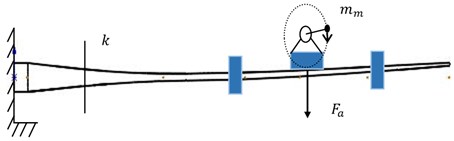
According to the principle of amplitude control in vibration mechanics analysis, it is assumed that the fixed mass of blade and surge system is , the mass of eccentric wheel is , the eccentricity is , the rotational angular velocity of rotor is , and the blade is regarded as two parallel springs with stiffness of . The resistance in the vibration process is simplified as the action of damper with damping coefficient parallel to the spring on the system the mechanical model of blade vibration is established, as shown in Fig. 1.
Fig. 1The mechanical model of blade vibration
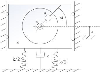
It can be seen that the amplitude of steady-state vibration is:
where is the frequency ratio, is the relative damping coefficient. According to the amplitude frequency response curve, when 1, the maximum amplitude is . When the motor frequency is close to the natural frequency of the blade and the whole excitation system, the amplitude will change sharply. When the blade reaches the maximum amplitude and the rotating arm position is horizontal, the blade reaches resonance.
2.2. Identification of fatigue test parameters
The natural frequency of wind power blades is obtained through modal tests. The data is direct and persuasive. It is a common method [17]. The blade is installed on a cylindrical test bed, the accelerometer is fixed at the blade tip, and the rotating mass vibration device is used to drive the blade vibration, the adaptive sweep frequency control system is to captures the resonance point of the blade, and gradually reaches the resonance peak and maintains the peak change rate within the error range required by the test. The host computer control system records the collected acceleration signals and completes the corresponding real-time signal processing. The modal test scheme is shown in the Fig. 2.
According to the time-domain response curve measured by the accelerometer DH610, FFT transformation is performed to obtain the frequency spectrum curves in the flap-wise and edge-wise directions.
As shown in Fig. 3(a), when the excitation frequency is obviously lower than the first-order natural frequency, the blade vibration is disordered, the amplitude fluctuates irregularly, and the amplitude value is small. When the excitation frequency is close but not equal to the first-order natural frequency, as shown in Fig. 3(b) and (d), the amplitude stability is improved. In Fig. 3(c), when the excitation frequency is equal to the first natural frequency, the blade amplitude increases steadily, and it can be maintained at the maximum amplitude of 1000 mm to reach the blade resonance. According to the modal test results, when the rotating frequency of the dynamic mass block of the excitation device is equal to the first-order natural frequency of the blade, the blade will reach a stable vibration state in a short time, and the vibration amplitude of the blade is the largest, thus reducing the energy dissipation and the demand for the excitation force during the fatigue test.
Fig. 2Testing model of wind power blades
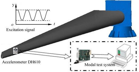
Fig. 3Simulation curve of amplitude change
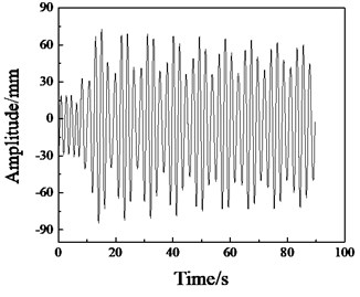
a) 0.70 Hz
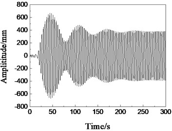
b) 0.74 Hz
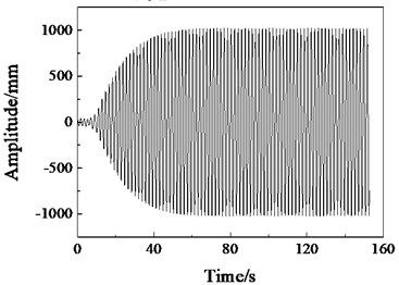
c) 0.78 Hz
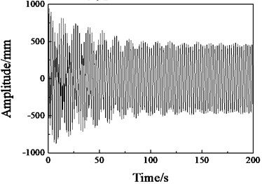
d) 0.82 Hz
2.3. Model construction of bending moment calculation
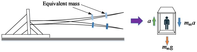
The main source of the bending moment of the wind turbine blade is the load and the weight of the blade. The introduction of the bending moment component of the blade’s own weight requires data such as the linear mass density distribution of the blade. According to the principle of equivalent substitution, the test blade equivalent to the cantilever beam structure is dispersed into cross sections along the span direction, with a total of masses of constant length, to obtain more accurate mass distribution. Fig. 4 is a simplified schematic diagram of uniaxial fatigue loading driven by a rotating mass. The bending moment acting on the blade section contains three components: the bending moment component M1 of self-weight, the moment component M2 of additional masses and static mass of the excitation device, and the bending moment component M3 of moving mass to drive the blade.
Fig. 4Uniaxial fatigue excitation model
The self-weight bending moment component of blade is as Eq. (2):
where, and are the discrete block number and total number on the right side of section respectively, and are the linear mass density and discrete block length of the discrete block numbered on the right side of section k, and is the first-order natural frequency of the blade. It can be seen that the excitation frequency of the rotating mass is equal to , is the amplitude at the center of gravity of the discrete block to which belongs, and is the distance from the center of gravity of the discrete block of number to the section .
The additional masses and the self-weight bending moment component of the driving device are as shown in Eq. (3):
where and are the number and total number of counterweights on the right side of section , is the mass of the added counterweight, is the distance of the added counterweight from the blade root, and is the cross section to the blade root. The distance, is the amplitude value at the center of gravity of the counterweight , and are the number and total number of the vibration excitation device on the right side of the section , is the static equivalent mass of the vibration excitation device, and is the amplitude value at excitation device of the excitation device numbered , is the distance from the excitation device numbered to the section , where, , , , , and are unknown.
The blade and entire excitation device can be equivalent to the relationship between elevator and people [4], as shown in Fig. 5. Taking the lowest point in the rotating process of the moving mass as time 0 point, the bending moment component of the driving force of the moving mass is as shown in Eq. (4):
where is the mass of the rotating mass, is the arm length of the rotating mass, and is the amplitude of the rotating mass relative to the blade:
Combined with Eqs. (2)-(5), the test bending moment values of various discrete sections along the blade span are calculated and used in the fitness function calculation of the subsequent intelligent optimization algorithm. The usual fatigue loading bending moment matching optimization is divided into two steps, one is to adjust the number of counterweights to achieve the optimization of the bending moment distribution, and the other is to distribute the weight and position of the weights to optimize the bending moment amplitude. In this paper, the two problems are combined to optimize the design of bending moment matching, and the optimization program for the additional masses and vibration device arrangement of wind turbine blades under uniaxial fatigue loading is developed.
Fig. 5Force model
3. Intelligent optimization algorithm development
Based on the force analysis, the calculation method of the target bending moment and the test bending moment, the program of additional and excitation arrangement optimization for moment matching of wind turbine blade under uniaxial fatigue loading is developed. Generally, the optimization of moment matching under fatigue loading is divided into two steps: the first step is to adjust the number of counterweights to optimize the moment distribution; the second step is to distribute the mass and position of counterweights to optimize the peak moment, and to design the magnitude of excitation force and counterweight mass.
This paper combines the two problems to optimize the moment matching at the same time, and the specific process is shown in Fig. 6.
The particle swarm optimization (PSO) simulates the foraging behavior of creatures such as birds or fish in nature. It is a random optimization algorithm based on group intelligent collaboration and information sharing. PSO has the advantages of few parameters, fast search speed, and no complicated evolution mechanism, so it is widely used in many fields. The basic idea of PSO algorithm is to find a set of parameter values under certain constraints to make certain indicators reach the maximum or minimum. Each particle in the particle swarm has a fitness value determined by position, velocity and fitness function, which represents a possible solution to the optimization problem. In each iteration, by comparing the current fitness value with the historical optimal value, the individual extremum and population extremum in the current iteration are obtained, and the optimal positions of the corresponding individual and population are recorded, so as to obtain the target optimal position and the optimal fitness value in the entire iteration cycle.
In this paper, the advanced strategies are introduced into the basic PSO, and the advanced particle swarm optimization (APSO) with linearly decreasing speed weight and asynchronously changing learning factors is designed to control the particle search speed and direction in real time. The speed weight , learning factors and change dynamically as Eqs. (6) and (7):
where, , are the maximum and minimum values of speed inertia weight respectively; is the maximum number of iterations; , , and are the initial and final learning factors of iteration respectively.
Fig. 6Program design of single fatigue loading test
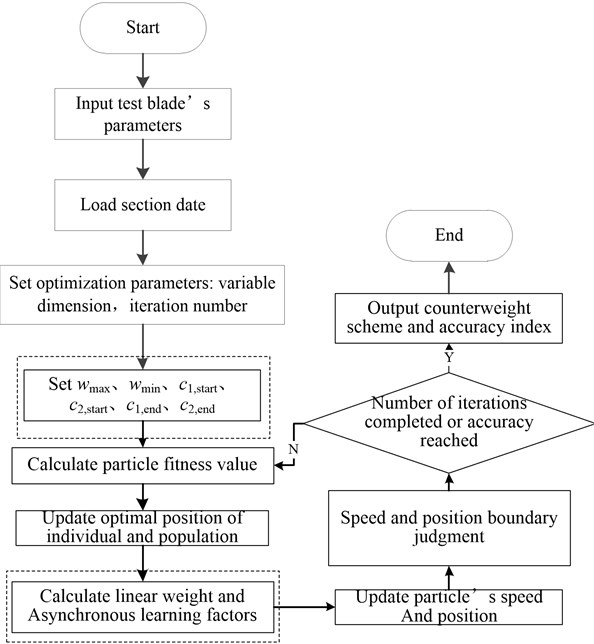
The main improvement operations in APSO is to add the parameters setting of , , , , , when initializing the parameters. Before updating the particle speed and position, the steps of linear weight and asynchronous learning factors calculation are added, as shown in the dashed box in Fig. 6. The objective function is the average section moment error of fatigue target load and test load, and the optimization fitness function subroutine is designed; the optimization location variable is the weight, position of the counterweight, the total mass and position of the excitation device (equivalent to the counterweight), which is twice the number of counterweight blocks. The main function program is designed based on the structure flow and constraints of the intelligent optimization algorithm. The first constraint is to control the moment matching accuracy within the range of the blade outline design, and the second constraint is to make the wind turbine blade get enough equivalent fatigue damage in a reasonable test cycle. The input data of the optimization program are: blade natural frequency, critical section amplitude, linear mass density distribution data, section stiffness data, initial counterweight position and weight. The sub-function code based on the moment calculation of each section is called to solve the counterweight scheme with the minimum matching error meeting the section moment constraint conditions.
The Griewank function as shown in Eq. (8) has many widespread local minima, which are regularly distributed. The complexity is shown in the zoomed-in Fig. 7(a). It is a common test function for objective optimization problems,and it is often used for comparison of different optimization methods:
It can be seen from the Fig. 7(b) that the optimal value of the function can be found by APSO method with relatively few iterations.
Fig. 7Griewank function and comparison between PSO and APSO
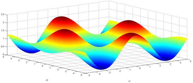
a) Griewank function
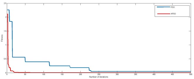
b) Comparison between PSO and APSO
4. Application study
4.1. Wind turbine blade’s information
Based on the data of 1.5 MW wind turbine blade, a case analysis of the optimization of bending moment matching of uniaxial resonance fatigue loading driven by a rotating mass was carried out. The total length of the blade is 40.3 m, the weight is 5943 kg, and the center of gravity is located at 12.25 m. The distribution curve of the linear mass and stiffness of the blade example is shown in Fig. 8.
According to the experiment, the first-order natural frequencies of the wind turbine blades in flap-wise and edge-wise directions are 0.78 Hz and 1.49 Hz, respectively. According to the optimization steps of the intelligent optimization algorithm in Fig. 6, the blade parameters, discrete mass distribution data, target bending moment are loaded into the main program, and the mass and position of the vibration excitation device and the counterweight are initialized according to the constraints of the variable value range. The test bending moments of each section are calculate according to Eqs. (1-4), the program written based on the mean square error is called, to calculate the accuracy error between the test bending moment distribution of the current counterweight scheme and the target bending moment distribution. According to this, iteratively updates the optimal population position, and finally obtains a counterweight arrangement plan that meets the bending moment matching accuracy index.
Fig. 8Linear mass density and stiffness distribution
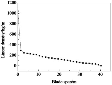
a) Linear density distribution
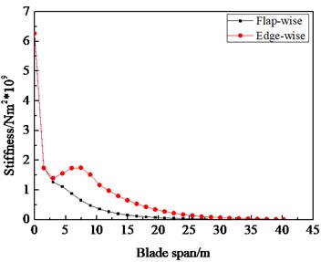
b) Stiffness distribution
4.2. Test verification
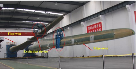
In order to verify the effectiveness of the algorithm in this paper, a uniaxial fatigue loading test as shown in Fig. 9 was carried out.
Fig. 9Uniaxial fatigue loading test
The bending moment matching situation and cross-section error of the flap-wise direction under the additional mass distribution scheme obtained by the APSO intelligent optimization algorithms are shown in Fig. 10.
It can be seen from Fig. 10(a) that the blade section bending moment distribution under APSO is consistent with the overall trend of the target bending moment distribution. As shown in Fig. 10(b), in the blade root and transition area, the bending moment error of the sections is small relatively, which ensures the matching accuracy of the bending moment of the critical section. The bending moment distribution error of the blade near the tip is large, and the test bending moment value is less than the target bending moment value, which is not conducive to the optimization of bending moment distribution technology. Therefore, when the bending moment matching optimization of the fatigue test is performed, the blade is generally truncated and sawed, that is to modify the inherent parameters of the blade in the optimization program, which is equivalent to adjusting the blade stiffness and mass matrix, so as to obtain more bending moment matching counterweight layout schemes, and further to improve the bending moment matching accuracy of wind power blade.
Through the test blade’s example analysis, the proposed APSO optimization algorithm is suitable for the optimization of bending moment matching of wind power blades under uniaxial fatigue loading test, the technical problem of low accuracy of bending moment distribution along blade span is solved. Based on APSO hybrid intelligent optimization algorithm, the bending moment matching counterweight and excitation device layout scheme of test wind turbine blade of uniaxial fatigue test in flap-wise and edge-wise directions is shown in Table 1.
Fig. 10Optimization results
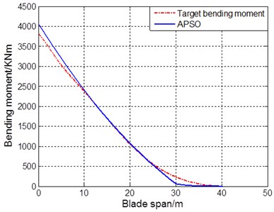
a) Bending moment matching result
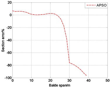
b) Cross-sectional error distribution
Table 1Distribution of additional masses and excitation device
Parameter | |||
Working condition | Additional masses and locations | Attributes | Fitness (KNm)2 |
Flap-wise | (20.4 m, 564 kg) | Counterweight | 7532 |
(28.3 m, 1760 kg) | Vibration device | ||
Edge-wise | (14.7 m, 700 kg) | Vibration device | 3215 |
(24.2 m, 670 kg) | Vibration device | ||
(35.5 m, 280 kg) | Counterweight | ||
In the global intelligent optimization algorithm, the initial position of the population position is random. Although the algorithm uses the same parameters, the layout scheme obtained by the algorithm is not completely consistent. Based on the same parameters: the population size is 40, the maximum iteration step is 100, and the bending moment matching of flap-wise direction of single-axis single-point excitation was performed. The distribution of single excitation point is shown in Fig. 10. It can be seen that the single-point excitation position is evenly distributed at 27 m, about 67 % of the total length of blade.
By comparison, the conventional method was through experience or simple calculation. Most of the blade testing manufacturers only obtain the counterweight scheme of wind turbine blade fatigue loading test moment matching only through experience or simple calculation. The accuracy of fatigue test data obtained from this is not high, which causes the test results of fatigue loading test to be distorted to a certain extent.
4.3. Equivalent damage determination
According to the additional masses and driving device’s optimization distribution scheme for bending moment matching of single axis fatigue test obtained in Section 3.2, the strain measurement in field test is carried out for fatigue verification. The test site is shown in Fig. 9, the blade test equipment (fixture, additional masses, motor, etc.) is installed, and the blade is tightened with hydraulic wrench when connected to the test bench. The leading edge of blade is vertical downward and the trailing edge is vertical upward. Before the test, the blades are calibrated for the first time according to the test program, so as to obtain the strain and deflection values of the key sections. The rotating mass is used to excite the blade to produce resonance. When the blade swings normally and stably, the strain value and deflection value of the key section reach the calibration value, the operation is successful. Strain gauges are arranged at each key section of the blade to collect the state information of the blade in real time. After the number of running target cycles, the equivalent damage of the blade is analyzed to verify the correctness of the equivalent scheme of moment matching. Based on the strain data of key sections 11 m, 14 m, 16 m and 20 m at suction side (SS) and pressure side (PS) collected by dynamic strain gauge Ex1629, the blade section damage value is calculated according to Eq. (9) [18]:
Fig. 11Distribution of excitation devise under uniaxial single point loading
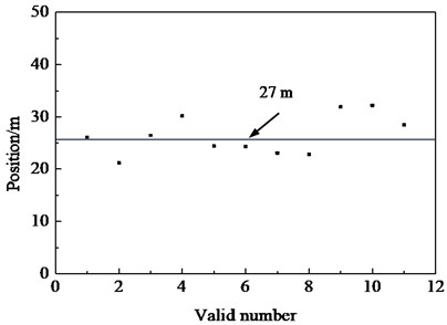
Table 2 is the statistical data result. Under the optimal counterweight scheme of moment matching of uniaxial fatigue loading, after the target number of fatigue cycle loading is set, the total damage D of section strain gauge is greater than 1, the key section of blade root and transition area reaches the equivalent damage, the blade does not have cracks, buckling, fracture and other defects, the actual service life of blade meets the design requirements of 20 years, the correctness and the validity of the counterweight scheme obtained by the moment matching optimization technology is verified.
Table 2Damage statistics at key sections
Section location | Strain gauge No. | Total damage value D | Average section damage | ||||
0-50 | 50-102 | 102-149 | 149-229 | ||||
11 m | SS | 0.198 | 0.283 | 0.176 | 0.431 | 1.088 | 1.279 |
PS | 0.164 | 0.421 | 0.435 | 0.452 | 1.471 | ||
14 m | SS | 0.293 | 0.439 | 0.208 | 0.498 | 1.438 | 1.221 |
PS | 0.198 | 0.228 | 0.204 | 0.375 | 1.005 | ||
16 m | SS | 0.251 | 0.255 | 0.219 | 0.306 | 1.003 | 1.009 |
PS | 0.208 | 0.260 | 0.200 | 0.347 | 1.015 | ||
20 m | SS | 0.191 | 0.281 | 0.337 | 0.451 | 1.259 | 1.139 |
PS | 0.169 | 0.274 | 0.210 | 0.367 | 1.019 | ||
5. Conclusions
Aiming at the problem that the bending moment matching accuracy of the uniaxial fatigue loading test is low, which leads to the failure to accurately obtain the fatigue characteristics of wind turbine blades. Combining the calculation model of bending moment and the advanced intelligent optimization algorithm, a complete set of bending moment matching optimization schemes for uniaxial fatigue loading test of wind turbine blades is designed.
The excitation point of the uniaxial single point fatigue loading test is about at 67 % of the total blade length, the key section of blade root and transition area reaches the equivalent damage under the counterweight scheme obtained by the optimization technology.
In this paper, the optimization technology of bending moment matching in full-scale loading test of wind turbine blade was studied. In order to obtain accurate fatigue test data, how to establish an accurate mathematical model of driving device to further improve the bending moment matching accuracy of fatigue test is also the direction of future research.
References
-
Pan Z. J., Wu J. Z., Zhao X. H., et al. Horizontal dual-point excitation and fatigue test of full-scale wind turbine blade. IOP Conference, 2017.
-
Lee H. G., Park J. Linear relationship of damping ratios in resonance-type fatigue testing of a wind turbine blade. Wind Energy, Vol. 17, Issue 7, 2014, p. 1119-1122.
-
Luo J. Research and Application of Improved Swarm Intelligence Optimization Algorithm. Wenzhou University, 2019.
-
Lee H. G., Park J. Optimization of resonance-type fatigue testing for a full-scale wind turbine blade. Wind Energy, Vol. 19, Issue 2, 2016, p. 371-380.
-
Zhang J. B., Shi K. Z., Xu J. Z. The improvement of additional mass settling method based on bending moment distribution equivalent for resonant fatigue test. Journal of Engineering Thermophysics, Vol. 39, Issue 3, 2018, p. 526-533.
-
Li Z. X., Liu W. S., Zhang X., Zhang L. A. Research on vibration characteristics of large-scale wind turbine blades during single-point fatigue loading process. Wind Energy, Vol. 12, 2015, p. 78-80.
-
Wu J. Z., Ye G. Z. Research on online evaluating of damage of wind turbine blade during fatigue test. Equipment Manufacturing Technology, Vol. 12, 2018, p. 23-26.
-
Xu L. J., Wang W. Q. Nonlinear Analysis of Structural Strength of Composite Wind Turbine Blades. Journal of Chongqing University, 2020.
-
Jin J. T., Liang P. C., Zeng J. C., Yang Y. H., Jiang Y. Finite element analysis for composite material wind rotor blade stiffness. Journal of Wuhan University of Technology, Vol. 31, Issue 21, 2009, p. 133-136.
-
Xue C. H., Li J. X., Wang C., Lu X. F. Finite element modeling and buckling stability analysis of composite wind turbine blades. FRP / composite, Vol. 1, 2014, p. 4-7.
-
Eberhart R. C., Shi Y. Comparison between genetic algorithms and particle swarm optimization. 7th International Conference on Evolutionary Programming VII, USA, 1998, p. 25-27.
-
Zhang J. B., Shi K. Z., Xu J. Z. Improved optimization method of equivalent weight for torque of wind turbine blade fatigue test. Journal of Engineering Thermophysics, Vol. 39, Issue 3, 2018, p. 526-533.
-
Greaves P. G., Dominy R. G., Ingram G. L., et al. Evaluation of dual-axis fatigue testing of large wind turbine blades. Proceedings of the Institution of Mechanical Engineers Part C: Journal of Mechanical Engineering Science, Vol. 226, Issue 2, 2012, p. 1693-1704.
-
Greaves P. R. Fatigue Analysis and Testing of Wind Turbine Blades. Durham University, 2013.
-
Sedighizadeh D., Masehian E., Sedighizadeh M., Akbaripour H. A new generalized particle swarm optimization algorithm. Mathematics and Computers in Simulation, Vol. 179, 2021, p. 194-212.
-
Pajak Michał Genetic-fuzzy system of power units maintenance schedules generation. Journal of Intelligent and Fuzzy Systems, Vol. 28, Issue 4, 2015, p. 1577-1589.
-
Le Y. F., Cheng G. Y., Zhu B. L. A new generalized particle swarm optimization algorithm. Mechatronics, Vol. 19, Issue 1, 2013, p. 26-29+44.
-
Lai F. M., Yang S. H., Wu J. H., et al. Development of fatigue test system for small composite wind turbine blades. Procedia Engineering, Vol. 14, 2011, p. 2003-2013.
Cited by
About this article

This work was supported by National Key R&D Program of China (2018YFB1501203), Shandong Provincial Natural Science Foundation, China (ZR2019MEE076).
