Abstract
Micro-Electro-Mechanical Systems (MEMS) is an integrated electromechanical system where the feature size and operating range of the components are on a micro-scale. Unlike traditional mechanical processing, the production of the MEMS device uses semiconductor manufacturing, which includes surface microprocessing and bulk microprocessing, which can be compatible with an integrated circuit. These devices or systems have the ability to detect, control, activate, and create macro-scale effects. In this study, a 3-channel microfluidic channel design was realized by using the SolidWorks program, which is a 3D design program, to realize a microfluidic chip design. The preliminary physical tests and investigation of this microfluidics were made using the Comsol Multiphysics program and necessary time-dependent pressure tests. In this study, it is aimed to understand the pressure and speed values of the microfluidic chip according to the analysis. As a result of the analysis, it was found that the microfluidic chip has a maximum pressure of 6.1 Pa and a speed of 2.36×1014 mm/s.
1. Introduction
The development of semiconductor technologies, companies working in this field have entered the race to reduce their production further and laid the foundations of today’s Microelectromechanical systems using different production methods. Studies in this field started in 1959. As the name implies, they are systems produced at micro and nano levels [1, 2].
Microfluidic chip systems are designed at micro levels, and there are channels through which electric current can go. It is defined as a group of canals or an integrated circuit in which channels through which fluid, air or heat pass through microfluidic channels range from a few µm to several mm.
In the 1990s, poly-dimethyl oxane (PDMS) was developed. With this development, it has been the most widely used in microfluidics and still has been widely used today. In the late 1990s, microfluidic devices were created for cell biology applications such as cell and protein separation modelling, cell-based biosensors, culture and research [3, 4].
Towards the 2000s, researchers began working on microfluidic devices that could be used as tissue and organ models for drug discovery and development and developed the organ-on-a-chip by examining biological processes. Since the 2000s, studies have been conducted on many tissue models on the intestine, liver, brain, heart, eyes, skin, lungs, muscles, blood vessels and the chip of the tumour [5-7].
By 2010, a biometric device was developed to mimic the lung alveolar-capillary interface with its structural, functional and mechanical aspects. The device has human alveolar epithelial cells on one side and human pulmonary-endothelial cells on the opposite or lower side. Human breath is imitated by injecting air into the sidewall or walls of the alveolus and then vacuuming [8-10].
In 2018, drug absorption was attempted on an organ chip made with a model taken from the intestine. In the microfluidic intestine, samples were placed in the upper part, and a porous membrane separating it from the bottom was placed to check whether the drugs given were absorbed.
In their work, Crowley and Pizziconi aimed to separate plasma from the blood by using planar micro filters for laboratory applications on the chip. He also stated that the micro-scale blood filtration design used in his study could have extensive effects in the field of separation science [11].
Abate et al. Found experimentally that their “T” connections on microfluidics are clogged over time. These connections in microfluidics are also found to occasionally block “T” rotations of fluids in the form of droplets [12].
In the multi-port flow control study for Chien and Parce Lab on a chip microfluidic devices, it aimed to reduce the time constant and develop an algorithm by calculating the pressures, and for this, it installed an additional device with an external pressure booster multi-port inlet. In this way, they emphasized that lab on a chip could open a new path for biochemical experiments. They have also explained that the ability to control liquids flowing in microfluidics is always a leading feature [13]. Pressure and speed control processes were carried out. There are many studies especially on control applications [14-16].
In this study, the micro-fluid chip design and analysis with three inputs and one output, and the pressure and speed in the microfluidic chip channels were controlled. These channels work in advancing blood, and it will be possible to examine for a chemical system and flow cell.
2. Material and methods
2.1. Design criteria
Lab on a chip (LOC) studies have become increasingly popular in areas such as biochemistry and bioengineering. It can incorporate all chemical processes such as chemical reactors, heat exchangers, separators and mixers by various techniques or methods.
In this study, the design study of the microfluidic with three channels inlet and the single outlet has been done. After modelling, optimization of infusion pressure, micro-channel design and time control is discussed.
– A single-output microfluidic design that can have three channel inlets
– A suitable 3D geometric drawing as microfluidic controls will be time-dependent
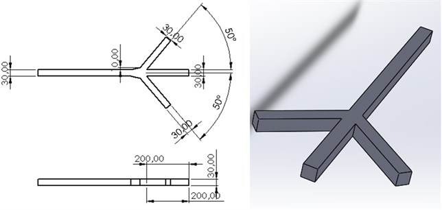
In Fig. 1, the three-channel microfluidic design is made and scaled. The channel width is 30×30 µm. The channels located close to each other are determined as the input channel and will be collected in the single-channel and will be the output channel.
Fig. 1Three channel microfluidic channel design
2.2. Comsol multiphysics analysis
In this study, analyzes will be carried out through the Comsol program, as time-based fluids will be studied through the microfluidic channel.
In Fig. 1, the microfluidic chip made with 3D design SolidWorks program was added to Comsol by “importing”. Then, the microfluidic chip meshed in accordance with the flow dynamics. Then, the input parameters for the inlet-outlet channel were defined, and the inputs and outputs were defined in the program. The fluid values passing through them are kept constant and are as given in Fig. 2.
Fig. 2Fluid properties

As indicated in Fig. 3, there are three input parameters. The explanations are as follows:
– p_in_rm: Pressure input in the microfluidic channel on the right side;
– p_in_c: Pressure inlet in the microfluidic channel in the middle;
– p_in_lm: Pressure input in the microfluidic channel on the left.
Fig. 3Three channel microfluidic inlet parameters

3. Result and discussion
3.1. Analysis with Comsol
With the completion of the design studies in the material and method, some tests were carried out using the finite element method to complete the pressure analysis based on time. In the previous section, dynamic viscosity and density are defined for the inclusion of the designed LOCs in the program, followed by entering the required pressure parameters for boundary conditions and fluid information. Finally, Mesh process has been done. Similarly, the necessary tests have started with the determination of inlets and outlets (outlet) determined on microfluidics.
In this study, volume flow analyzes on the microfluidic chip were evaluated over 0.5 s.
Fig. 4Three channel microfluidic (t= 0.5) flow direction
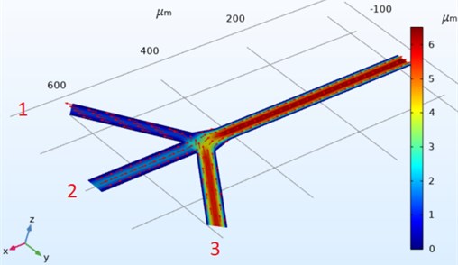
The direction graphs of the speeds on the Three Channel microfluidic design are shown in Fig. 4. The entrances of the channels are numbered from left to right. Using the equation according to the numbers, the flow, pressure effect and flow direction of the fluid varies in the channels. The most velocity flow flows from the single output point and reaches a speed of 2.36×1014 mm/s. In the number one input, the speed is almost between 0 and 1 mm/s, but the speed direction is opposite to the input direction.
3.2. Pressure-time analysis
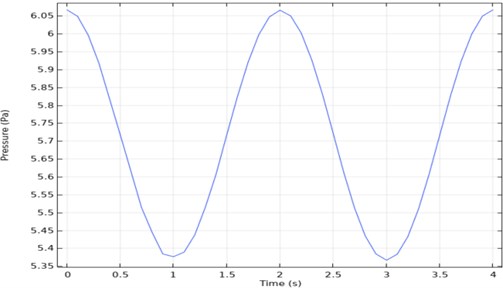
Time-dependent analysis of pressure is taken from one point of the outlet. When the output graph in Fig. 5 is examined, it will be seen that it is periodic. According to this graph, the maximum pressure was 6.1 Pa, and the minimum pressure was 5.37 Pa.
Fig. 5Three channel microfluidic pressure-time graph
3.3. Speed-time analysis
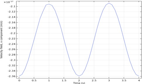
Time-dependent analysis of speed is taken from one point of the output. When the output graph in Fig. 6 is examined, it will be seen that it is periodic. According to this graph, the maximum speed was 2.36×1014 mm/sec, and the minimum speed was 2×1014 mm/sec.
Fig. 6Three channel microfluidic velocity-time analysis
4. Conclusions
Until recently, the development of miniaturized non-electronic devices has lagged behind the miniaturization trend in microelectronics. In the late 1970s, silicon technology also expanded the processing of mechanical microdevices, and later became known as microelectromechanical systems (MEMS). However, although it is common to use MEMS as the term of microtechnology used today, it is not true. With the fluid and optical components in microdevices, microsystem technology (MST) appears as a more accurate definition.
In this study, the SolidWorks program, one of the 3D design programs, was used to realize a microfluidic chip design. For the preliminary physical tests and investigation of this microfluidic, the time and pressure-dependent velocity analyzes were performed using the Comsol Multiphysics program using the finite element method.
According to the analysis of the microfluidic chip, pressure and velocity values were obtained in this study. As a result of the analysis, it has been observed that the microfluidic chip has a maximum pressure of 6.1 Pa and a speed of 2.36×1014 mm/s. These values obtained will be of great importance in the fabrication of the chip. Also, it is thought that this study will be an essential resource for future stages.
References
-
Ertugrul I., Akkus N., Yuce H. Fabrication of bidirectional electrothermal microactuator by two-photon polymerization. Materials and Technology, Vol. 53, Issue 5, 2019, p. 665-670.
-
Ertugrul I., Akkus N., Aygul E., Yalcinkaya S., Ertunç H. MEMS fabrication using PµSL technique based 3D printer. International Journal of 3D Printing Technologies and Digital Industry, Vol. 4, Issue 1, 2020, p. 38-43.
-
Folch A., Toner M. Cellular micro models on biocompatible materials. Biotechnology Programs, Vol. 12, Issue 3, 1998, p. 388-392.
-
Shang L., Cheng Y., Zhao Y. Emerging droplet microfluidics. Chemical Reviews, Vol. 117, Issue 12, 2017, p. 7967-7968.
-
Whulanza Y., et al. Realization and testing of lab-on-chip for human lung replication. Journal of Engineering and Applied Sciences, Vol. 9, Issue 11, 2014, p. 2064-2067.
-
Ghaemmaghami A. M., Hancock M. J., Harrington H., Kaji H., Khademhosseini A. Biomimetic tissues on a chip for drug discovery. Drug Discovery Today, Vol. 17, 2012, p. 173-181.
-
Huh D., Matthews B. D., Mammoto A., Montoya-Zavala M., Hsin H. Y., Ingber D. E. Reconstruction of lung function at the organ level on a chip. Science, Vol. 328, Issue 5986, 2010, p. 1662-1668.
-
Williamson A., Singh S., Fernekorn U., Schober A. The future of the body on patient-specific chips. Lab Chip, Vol. 13, Issue 18, 2013, p. 3471-3480.
-
Moraes C., Labuz J. M., Leung B. M., Inoue M., Chun T. H., Takayama S. Being the right size: scaling effects in the design of a person on a chip. Integrative Biology, Vol. 5, 2013, p. 1149-1161.
-
Esch E. W., Bahinski A., Huh D. Organs on chips at the borders of drug discovery. Nature Reviews Drug Discovery, Vol. 14, Issue 4, 2015, p. 248.
-
Crowley T. A., Pizziconi V. Isolation of plasma from whole blood using planar microfliter for lab-on-a-chip applications. Journal of Royal Society of Chemistry, Vol. 5, 2005, p. 922-929.
-
Abate A. R., Mary P., Steijn V. V., Weitz D. A. Experimental validation of plugging during drop formation in a T-junction. Lab Chip, Vol. 12, Issue 8, 2011, p. 1516-1521.
-
Chien R. L., Parce W. J. Multiport flow-control system for lab-on-a-chip microfluidic devices. Springer, Vol. 371, Issue 2, 2001, p. 106-111.
-
Kuncan M., Kaplan K., Fatih A. C. A. R., Kundakçi I. M., Ertunç H. M. Fuzzy logic based ball on plate balancing system real time control by image processing. International Journal of Natural and Engineering Sciences, Vol. 10, Issue 3, 2016, p. 28-32.
-
Öztürk S., Karakuzu C., Kuncan M., Erdil A. Fuzzy neural network controller as a real time controller using PSO. Journal of Engineering and Science – APJES, Vol. 5, Issue 1, 2017, p. 15-22.
-
Kaplan K., Kundakci I. M., Kuncan M., Toprak E., Izgu A., Ertunc H. M. Process control methods application in training set. International Journal of Natural and Engineering Sciences, Vol. 10, Issue 2, 2016, p. 35-42.
About this article

