Abstract
Suspension system is one of the challenging portions in designing a vehicle. The complete stability of the vehicle under dynamic conditions depends on the suspension system of the vehicle. Suspension system of a vehicle is interlinked with other systems such as steering, Wheels and Brakes. The main objective of this document is to provide complete guidance in designing and calculation of an independent suspension system with double control arms. The required parameters are calculated on considering a prototype vehicle with gross weight of 350 kg such as required stiffness of shock absorbers, Ride frequency, Motion ratio, Coefficient of damping etc. A CADD model was made with CATIA v5 r20 and SOLIDWORKS on the basis of calculations obtained and stress analysis was carried out for this model in various software such as Ansys. The complete assembled model was tested in LOTUS Shark and the result was obtained.
Highlights
- Calculation are performed on considering a prototype vehicle of 300 Kg.
- Basic terminologies are explained only then advanced calculations are performed.
- Ultimate aim is focused on real time manufacturing.
- Each and every Minute Constrains are considered for efficient performance.
- Accuracy of the result is high due to the usage of softwares such ANSYS, Lotus suspension etc.
- Provides guidance for designing suspension for various applications.
1. Introduction
According to Douglas L. Milliken and William F. Milliken [1], The design of suspension system for high performance cars involves assumption of parameters such as Roll rate and it involves verifying them at end. Several iterations have been in order to attain perfection in riding conditions in corners considering lateral load transfers. As John C. Dixon [2] elaborately discusses all the parameters related to a suspension system of a vehicle which provides a complete understanding of the concepts and our manuscript is scripted in such a way that only the exact required parameters are described and used for the calculation. The independent double arm Suspension system consists of Control arms, springs, Dampers and linkage mechanisms that connect the wheel and the Roll cage of a vehicle. The relative movement between the wheel and the Roll cage is obtained by this suspension system [3]. Double arm independent suspension systems are widely preferred as they have high ride stability and reliability [2]. This is due to negative camber gain they attain, thereby also increasing the traction in corners. This ultimately provides good handling for the vehicle [2-5]. Here in this design a perfect camber gain is achieved providing a balance between braking grip and cornering grip. The design and calculations carried out is based on a prototype vehicle of mass 350 kg. In Terms of manufacturing coilover shock absorbers, the calculation of coil diameters ratio is also performed [6]. We have figured out an efficient method of approach in designing a suspension system for a vehicle after undergoing an elaborate research work on vehicle dynamics and various methods to design a suspension system of a four wheeled vehicle [1-13].
2. Working principle
The basic principle of this type of suspension systems is absorption of mechanical energy and dissipating them as heat in shock absorbers [2]. It provides a relative motion between the wheels and the Roll Cage thereby reducing the force that is transmitted from wheel to Roll Cage [1-3]. Thus, the comfort and the safety of passengers relies on the suspension system. In dynamic conditions, the spring compresses storing the impact force (jounce) and the spring expands (rebound), the vibration is ceased by dampers.
3. Constraints to be considered
3.1. Major parameters to understand
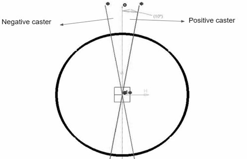
1) Caster angle. Consider a wheel from the side view of a car. Inclination of the upper point of the steering axis towards vehicle frame is considered as a positive caster and away from frame is Negative caster [2].
Fig. 1Side view of a front left side wheel to define caster
2) Camber. Consider a car from the front view. Difference in distance between top end and bottom end of a pair of wheels coins the term camber.[2]
Fig. 2Positive camber (front view)
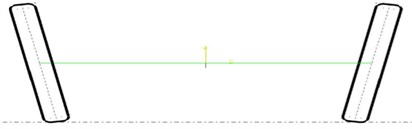
Fig. 3Negative camber (front view)
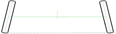
3) Toe-in and toe-out. Consider a pair of wheels from the top view. Difference in distance between front end and rear end of a pair of wheels coins the term toe in and toe out [2].
Fig. 4Toe-in (top view)

4) Kingpin inclination. Considering from the front view, the angular displacement of the steering axis coins the term King pin Inclination (KPI). It is also known as Steering Axis Inclination (SAI) [2].
Fig. 5Toe-out (top view)
3.2. Force consideration
– Static-force due to gravity, reaction force in wheels.
– Dynamic – longitudinal acceleration and hard braking resulting in dive, lateral forces resulting in rolling of vehicle, vertical gravitational force under dynamic condition of vehicle [3, 4].
3.3. Design consideration
– The shape and dimension of the control arm or wishbone depends on the available space and the stress withstanding capability (moment of inertia as a factor).
– The front arm can take “A” equivalent shape, the rear can take “A” or “H”-equivalent shape.
– The desired ground clearance was fixed GC = 10” (As per requirement).
– Track width: 1143 mm.
– Wheel base: 1524 mm.
– The roll centre axis and pitch centre axis are imaginary axis, they can be determined from the inclination of the control arms with respect to the roll cage and wheel assembly.
1) Roll Center. The axis about which the car tends to roll. This axis intersects the point at which the lines extended from the patch contact point of tyre to instantaneous points of both wheels meet.
Fig. 6Roll center fixing (front or rear view). Note: it should be near to centre of gravity for good cornering performance
2) Pitch center. The axis about which the car tends to dive or squat.
– Required jounce: 2”; required rebounce: 2” (As per requirements).
– Fixed roll center: 260 mm (from ground).
– Obtained center of gravity: 480 mm (from ground).
– Methods to find the center of gravity height:
a) Practical: either front or rear side of the vehicle have to be lifted to approximate height. Weighing machines have to be placed on both the front wheels and rear wheels of the vehicle. Weight before lifting and after lifting have to be noted and applied in the formula to get approx CG.
Formula = (level wheelbase×raised wheel base×added weight on front wheels)/(distance raised×total vehicle weight).
To find CG distance from rear axle = (weight at front×wheel base)/total weight.
b) CAD Method: the components must be designed assuming their mass and the position of Centre of gravity must be found in the complete assembled design of vehicle.
4. Formula and calculations
Calculation for a prototype vehicle on considering:
– Track width 3.75 ft or 1143 mm.
– Wheel base 5 ft or 1524 mm.
– Height of roll centre front 0.833 ft or 260 mm.
– Height of roll centre rear 0.82 ft or 254 mm.
– Height of C.G. 1.57 ft or 480 mm.
– The vertical distance between C.g and roll axis 0.74 ft.
– : 65:35.
– 661 lbs.
4.1. Stiffness calculation
Considering the vehicle to enter a corner at 41.01 ft/s. The centripetal force due to friction:
The centrifugal force:
From Eq. (1) and Eq. (2) we get: 74 ft ≅ 82 ft.
Considering longitudinal acceleration and drive torque to be zero, 0 lbs-ft, 0 g’s, and:
where -in terms of ft/s2:
Condition: If the roads are banked. Longitudinal weight transfer is much smaller than lateral weight transfer so we lateral weight transfer.
The component of lateral acceleration along the axis of the car: 5, , –0.5498 g’s (negative sign indicates deceleration), Note: (if road is level).
Position of Centre of Gravity. The cad model reference was taken for finding the position of C.G in side view, 990 mm = 3.25 ft and 533.4 mm = 1.75 ft.
Resulting in: 214.825 lbs, , 115.675 lbs, .
Effective weight transfer due to banking: , 695.13 lbs, 451.83 lbs, 243.29 lbs.
Roll gradient: Assuming roll rate 200 lbs-ft/°, (desired for high performance in corners), 65 % of 200 = 130 lbs ft/° = 7448.45 lbs ft/rad, 35 % of 200 = 70 lbs ft/° = 4010 lbs ft/rad.
Lateral load transfer due to lateral acceleration:
Load on individual wheel after the effect of lateral acceleration for inner and outer: 243.29/2 + 53.24 = 174.885 lbs, 24.29/2 – 53.24 = 68.40 lbs, 451.83/2 + 98.89 = 324.805 lbs, 451.83/2 – 98.89 = 127.025 lbs.
Change from static load to dynamic load: 174.885 – 115.65 = 59.235 lbs, 68.40 – 115.65 = – 47.25 lbs, 324.80 – 214.825 = 109.0975 lbs, 127.025 – 214.825 = –87.8 lbs.
Total braking force, consideration (varies vehicle to vehicle):
1) Mass (sprung mass + unsprung mass) = 400 kg.
2) Speed = 45 km/hr.
3) Displacement 3 m.
1/2= 1/2·400·12.52 = 3.12·104 J, workdone / = (3.12·104) / 3 = 10400 N.
Effective load transfer due to braking: Static Load + Load Transfer effect = 231.35·990/1524 + 10400·480 / 1524 = 150.29+3275.5, 3425.8 N = 770.15 lbs, 770.15/2 = 385 lbs.
The ride rate of the vehicle, considering ride travel 2 inches in front and 1.5 inches in the rear: – change/ride travel, 59.325/2" lbs/inch, 29.66 lbs/inch, 109.975/1.5" lbs/inch, 73.3 lbs/inch.
Considering longitudinal load transfer (385 – 115.65) / 4" = 269.65 / 4" = 67.4125 lbs/inch.
Ride frequency:
To verify assumed roll rate:
Hence the assumed roll rate is proved.
The new roll rate 11822.92 lbs ft/rad.
For independent suspension the wheel center rate is, .
Considering, 2015 lbs/inch or 36 kg/mm (Standard value) [1-6], (67.41·2015) / (2015 – 29.66) = 69.74 lbs/inch, (73.3·2015) / (2015 – 73.3) = 76.06 lbs/inch.
Installation ratio. Consider the shock absorber to be mounted in the lower arm and the lower arm is parallel to the ground level.
Fig. 7Installation ratio (IR) and mounting angle determination, where L – load on the spring, θ –mounting angle of shock, R – normal reaction force on wheels, X – distance of mounting point from inner end of arm, Y – length of mounting control arm, A – point of control arm on roll cage, B – wheel centre point
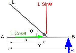
Taking moment about “” as zero:
After several iterations, considering the fact increasing “” makes the ride stiffer and decreasing “” increases spring force: 60° and 0.68 is chosen, 1252.62 N, 542.4 N, 1138.38 N.
Lateral force considering zero banking , 654.93 N.
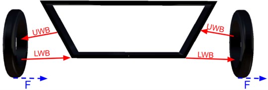
Here the horizontal component “”and “” constitutes two couples on the wheel, these forces produce two equal and opposite forces to them respectively on the upper half of the wheel pressing the upper arm inwards i.e. towards the chassis as shown in Fig. 9.
Considering vertical forces due to uneven roads “3g force is considered”, thus in case of coilover shock absorber, spring chosen or manufactured must be progressive spring or dual rate springs.
Fig. 8Skeleton sketch of Wishbones (WB) mounting
Thus the second rate of spring be, 3·150.82 lbs/inch, 3·164.48 lbs/inch.
Critical damping , 107.8 lbs-s/ft.
For passenger cars: damping ratio = 0.3, , 0.3 = / 107.8, coefficient of damping 32.34 lbs-s/ft.
4.2. In case of manufacturing a coilover shock absorber
Shear stress:
410 N/mm2 (considering F.O.S = 1.5) and 1687.32 N, also:
We get .
If 5 then 10 mm and 50 mm. From the above equation assuming . We can calculate and .
Also, from:
From above equations we can determine the parameters of required spring parameters.
4.3. To choose Wishbone material
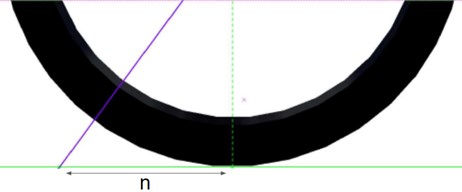
where – first moment of area, – load, – thickness of pipe, .
Based on market availability and CAD analysis and values can be determined:
Fig. 9Centroid Point from the central axis of a pipe
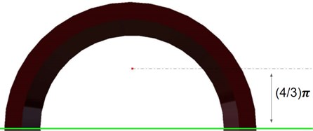
Thickness of pipe 1.5 mm, 89.23 N/mm2.
A prototype material “Chromoly” is taken for consideration. Based upon the value of chromoly, 80 GPa (AISI 4130 ) = 80·103 N/mm2, shear stress/shear strain = , shear strain = 89.23 / (80·103) = 0.0011154 (Too small).
Hence the material selected undergoes very less deformation with a given load. The material chosen is perfectly suitable for Control arms.
5. Component design and selection
Based on the obtained calculation values, space available, along with the tolerance required, shape and dimension of wishbone and coil spring is found.
Market survey is the most important phase of manufacturing. Inorder to know the availability and presence of different types of raw materials in the market. Based on availability one can decide their own efficient way of manufacturing or to go with OEM products that are available.
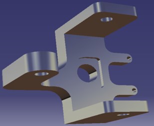
5.1. Knuckle design
In order to achieve the required riding condition, the knuckle design plays a major role [13]. The fixing of the parameters such as Caster, Camber, Toe angles and King Pin Inclination majorly depends on the design of a knuckle. The dimension and shape of a knuckle is completely dependent on those parameters in order to obtain the efficient ride quality.
Fig. 10Knuckle design-front
5.1.1. King pin inclination
King pin inclination determines the scrub radius. The scrub radius plays a major role while applying brakes. Short long arm suspension usually has positive scrub radius as scrub radius does not vary. The vehicle with diagonal braking system has negative scrub radius, this is due the fact that it aids in braking upon failure of one unit of diagonal braking system. Higher value of scrub radius aids braking and reduces steering effort but increases steering sensitivity to braking. Hence an optimum level must be chosen. Prototyping vehicle is equipped with an KPI of 4°.
5.1.2. Castor angle
Positive castor induces a aligning torque whereas negative castor reduces steering effort. Aligning torque is a favourable factor, so many designs go with a positive castor.
The angle depends on wheel diameter, i.e .
Caster angle of 4.43° is considered for the prototyping vehicle.
Fig. 11Positive caster
5.1.3. Camber angle and toe
Negative camber helps in cornering increasing patch contact of outside tires, whereas vehicles of higher mass prefer positive castor as they create stability to the vehicles. Toe plays a major role in straight line stability (toe in) and cornering stability. The fact that camber and toe make the tire wear out soon makes them unpreferable for most commercial vehicles.
5.2. Selection and design of wishbones and its material
– There are plenty of materials available in many cross-sectional shapes. Each material has its own Young’s modulus value.
– The required material and shape are decided based on the strength of the material.
– The dimension of wishbones and its design is carried out based on the space available along with other important parameters such as Caster, Camber, KPI, roll center and pitch center.
– Wishbone mounting points: Designing the mounting points for the wishbones is an important part. Fixing must be carried out by considering the roll center, pitch center and RC member’s strength.
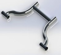
Fig. 12A-equivalent front lower wishbone design
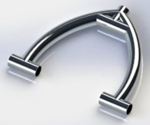
Fig. 13H-equivalent rear lower wishbone design
The maximum shear stress was calculated and the material for wishbone was selected as Chromoly AISI 4130 seamless tubes (Not limited to this). The Diameters and minimal thickness can be determined with the help of software such as ANSYS.
5.2.1. Part analysis
To determine Diameter and Thickness required, Part analysis is carried out with the software called “ANSYS”. By fixing the maximum load and gradually decreasing the diameter and thickness of the pipe, a safer dimension could be found.
As a result of analysis with factor of safety:
– Diameter of the pipe: 25 mm.
– Thickness 1.5mm.
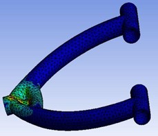
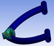
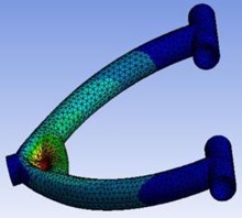
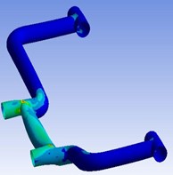
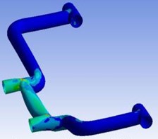
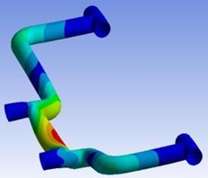
Fig. 14 and Fig. 15 shows the analysis of designed wishbones via ANSYS Workbench software. That depicts that the calculated values to design wishbones are prominently best suited for the considered prototype vehicle.
Fig. 14a) Equivalent strain, b) maximum principal stress, c) total deformation
a)
b)
c)
Fig. 15a) Equivalent strain, b) maximum principal stress, c) total deformation
a)
b)
c)
5.3. Design and selection of shock absorbers
Based upon the required stiffness value of the vehicle, shock absorbers could be selected or manufactured as required among various types of shock absorbers.
To design a coilover shock absorber, the calculated Diameters ratio and material stiffness of the spring coil have to be considered as primary parameters.
Fig. 16Coilover shock absorber design
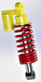
Based on the calculations a coilover shock absorber with damper is chosen.
– Mean coil diameter 74 mm.
– Coil diameter 11 mm.
– Number of turns of coil 6 + 3.
– Solid length 99 mm ().
– Free length 170 mm.
6. Result analysis
The obtained results have to be properly analysed in order to present the accurate results which in turn shows the best practical outcome.
The coordinates of all assembled parts obtained with the help of Creo, Catia etc. and have to be given as an input in lotus.
Fig. 19Dynamic analysis of results in LOTUS shark software-rear wheel
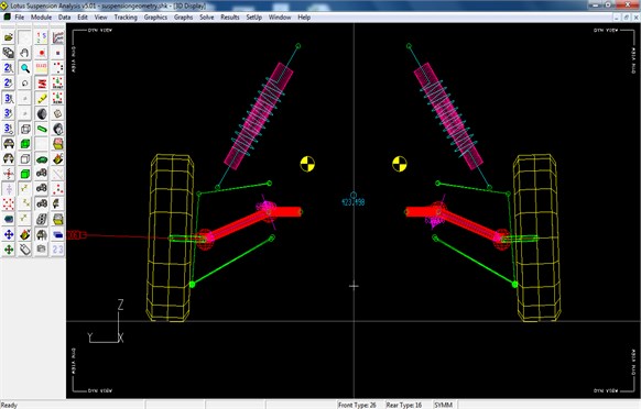
Table 1Results obtained
Parameter | Obtained data (theoretical) | Designed components (actual) |
Stiffness | Front: 150.83 lbs/in || 450 lbs/in Rear: 164.48 lbs/in || 493 lbs/in (With 3g Bump) | Coilover Shock Absorbers: 590 lbs/in |
Coil diameter ratio | Assuming, 6 Then 13 mm and 78 mm Minimum no. of active turns required as per calculation = 7.5+2 Thus, the solid length 97.66 mm | Based on Space/Market availability: – Mean coil diameter 74mm – Coil diameter 11mm – Number of turns + 3 = 6 + 3 – Solid length 99mm, () |
Fixed Roll Center | 260 mm (from ground) Suggested: as close as to C.G | 260 mm (from ground) |
King Pin Inclination | Based on required scrub radius | 4° |
Caster | Required aligning torque | 4.43°(positive) |
Wishbone | Shear stress / Shear strain = (Strain: As low as possible) Minimum shear strain = 0.002 | Material: Chromoly 80 GPa (AISI 4130), 1.5 mm, 12.7mm, Shear strain = 89.23 / (80·103) = 0.0011154 (Too small) |
Damper | 107.8lbs-s/ft, Damping ratio 0.3 (For passenger vehicle) Coefficient of damping: 32.34lbs-s/ft | |
The obtained values of the calculation and the angles fixed such as caster angle, camber angle and KPI are analysed with the help of LOTUS Shark Software. The net camber gain for various bump travel is found using lotus. The above picture shows analysis.
Prototype conditions:
I. Track width = 1143 mm.
II. Stiffness of spring = 50 N/mm || 100N/mm || 300 N/mm (as per the reports from a reputed laboratory).
III. Bump = 60 mm.
IV. Installation ratio = 0.68.
Arm configuration and mounting point was provided.
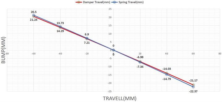
Results are deputed in Fig. 20, 21 with bump travel across -axis.
The calculated values are given as an input to the software Lotus Shark. Figs. 20, 21 is formed from the final results obtained from the software.
Fig. 20Result analysis of geometrical values- front wheel
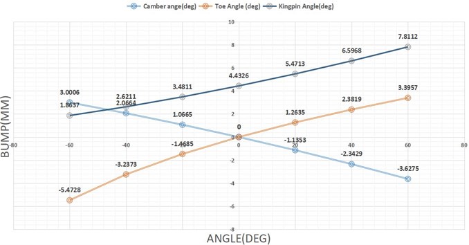
Fig. 21Result analysis of spring and damper travel in mm
7. Conclusions
The carried out Novel research is in terms of manufacturing a vehicle with an independent double arm suspension, that is elaborated on considering a prototype vehicle of 350 kg. The research manuscript depicts the simplest methodology that could be followed in order to design an accurate suspension system of a car. It covers the basic parameters that have to be known before proceeding with calculations followed by all the basic and advanced calculations such as Stiffness Required, Installation ratio, Wishbone material, Coefficient of damping etc. Based on the obtained values, the components design is carried out. Designing of Coilover shock, Designing of Knuckle and Designing of Wishbones is carried out. The significant usage and every technical aspects are considered while designing, such as the selection of material, type of components, dimension, and cross-section of the component. The calculations obtained are considered enough to satisfy other parameters that have to be possessed while manufacturing a complete vehicle. The test conditions give an overall efficient performance and it proves the effectuality of manufacturing a real-time suspension based on the international market with a proper progression of schematic procedures and methodology. These results demonstrate that a customized, high performance, the operational suspension system can be manufactured easily. The real benefit is, this can assist any person to manufacture and design a suspension system as a high performance operational suspension system. The Ultimate scope of easily understandable and efficiently operational suspension system designing is successfully achieved.
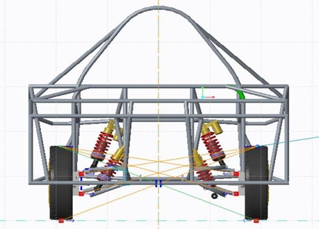
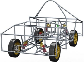
Fig. 22Assembled vehicle with shock absorbers and wishbones
References
-
Milliken William F. Race Car Vehicle Dynamics. Society of Automotive Engineers, 1995.
-
Dixon John C. Suspension Geometry and Computation. John Wiley and Sons, 2009.
-
Gillespie Thomas D. Fundamentals of Vehicle Dynamics. SAE International, 1992.
-
Ball Jeffrey K., Stone Richard Automotive Engineering Fundamentals. SAE International, 2004.
-
Giri N. K. Automobile Mechanics. Khanna Publishers, 2008.
-
Ashish Avinash Vadhe Design and optimization of formula SAE suspension system. International Journal of Current Engineering and Technology, Vol. 8, Issue 3, 2018, p. 609-635.
-
Balaji D. S., Prabhakaran S., Umanath K. Design and analysis of the double wishbone suspension system. Journal of Advanced Research in Dynamical and Control Systems, Vol. 9, Issue 2, 2017, p. 987-993.
-
Tambe Tushar Digambar Design and development of front-suspension system of an off-road vehicle. International Journal of Recent Research and Review, Vol. 10, Issue 4, 2017, p. 39-44.
-
Mahesh More H., Shekhar Yadgiri Gajjal Design and analysis of flat joint connection of double wishbone suspension A arm. IOSR Journal of Mechanical and Civil Engineering, Vol. 13, Issue 4, 2016, p. 114-121.
-
Nayan Deshmukh, et al. Design of double wishbone suspension system of BAJA vehicle. International Journal of Advance Engineering and Research Development, Vol. 4, Issue 12, 2017, p. 852-859.
-
Nikita Gawai Design, modelling and analysis of double wishbone suspension system. International Journal on Mechanical Engineering and Robotics, Vol. 4, Issue 1, 2016, p. 58-62.
-
Konieczny Łukasz, Burdzik Rafał Modern suspension systems for automotive vehicles and their test methods. Vibroengineering Procedia, Vol. 14, 2017, p. 233-237.
-
Sanjay Yadav, Ravi Kumar Mishra, Varish Ansari, Shyam Bihari L. Design and analysis of steering knuckle component. International Journal of Engineering Research and Technology, Vol. 5, Issue 4, 2016, p. 457-463.
About this article

We are grateful to a solar car manufacturing team “Xtreme Mechons 2.0” of Rajalakshmi Engineering College, Chennai for giving us this opportunity to work on suspension system and also thank the team for providing all essential support to successfully manufacture a vehicle.
