Abstract
In order to investigate the causes and development characteristics of rail corrugation on the tangential section, based on the finite element model of track structure and the vehicle-track space coupled dynamic model, modal analysis and dynamic analysis were carried out for detailed analysis. The results show that the line condition and passing frequency range of measured corrugation are close to those of roaring rail corrugation caused by Pinned-Pinned resonance of track structure, so it is preliminarily considered that corrugation occurring on this section is roaring rail corrugation. The modal analysis of track structure model shows that the vibration mode at the frequency of 513.7 Hz is the transverse Pinned-Pinned resonance of track structure and the vibration mode at the frequency of 1050.0 Hz is the vertical Pinned-Pinned resonance of track structure. The dynamic analysis of vehicle-track space coupled model shows that the amplitudes of rail vertical vibration acceleration levels are higher at the center frequencies of 500 Hz and 1000 Hz, and the one-third octave band widths corresponding to above center frequencies are in the frequency range of Pinned-Pinned resonance of track structure. Therefore, it can be determined that rail corrugation on the measured line is roaring rail corrugation. The changing trends of rail vertical vibration acceleration levels under different sleeper spacings and operating speeds are basically the same and amplitudes of rail vertical vibration acceleration levels at the center frequencies of 500 Hz and 1000 Hz are higher. With the increase of the sleeper spacing and operating speed, the variation trends of rail vertical vibration acceleration levels at 500 Hz and 1000 Hz are almost unanimous. By changing the sleeper spacing and operating speed, the rail vertical vibration acceleration levels can be changed significantly, which shows that the appropriate sleeper spacing (about 700 mm) and operating speed (about 80 km/h) can effectively control the occurrence and development of rail corrugation.
Highlights
- The line condition and passing frequency range of measured corrugation are similar to those of corrugation induced by Pinned-Pinned resonance of track structure.
- The vibration mode at 513.7 Hz is the transverse Pinned-Pinned resonance mode, and the vibration mode at 1050.0 Hz is the vertical Pinned-Pinned resonance mode.
- The dynamic analysis results contain characteristic frequencies close to passing frequencies, and these frequencies are in the frequency range of Pinned-Pinned resonance of track structure.
- The appropriate sleeper spacing (about 700 mm) and operating speed (about 80 km/h) can effectively control the generation and development of roaring rail corrugation.
1. Introduction
Urban rail transit makes transportation more convenient, but much problems of vibration and noise which have a greater negative impact on the environment come out [1, 2]. In order to alleviate the damage caused by vibration and noise, different forms of vibration reduction measures have been applied in the rail transit industry, in which the installation of damper fasteners is one of the commonly used measures for the track structure. However, there is rail corrugation of various degrees on the rail surfaces of Beijing Metro [3], Shanghai Metro [4], Guangzhou Metro [5], etc., which use a large number of damper fasteners. Corrugation is a kind of non-uniform and periodic wear on the longitudinal rail surface. The slight corrugation is generally eliminated by rail grinding, but for the serious corrugation damage, the rail must be replaced to ensure the safe operation of vehicles.
Rail corrugation is a major technical problem that has not been solved in the railway industry so far. Based on the current analysis methods and long-term investigations with tests, it is found that the generation and development of rail corrugation are closely related to the inherent vibration characteristics of vehicle-track system. According to the wavelength fixing mechanism and material damage mechanism, Grassie et al. [6] classified the causes of rail corrugation into six categories, including Pinned-Pinned resonance, rutting, heavy load, light rail, special track form and other P2 resonance, in which the corrugation caused by Pinned-Pinned resonance mainly occurred on tangential and large radius curve tracks and the typical vibration frequency range of vehicle-track system was 400-1200 Hz. Böhmer et al. [7] studied the influence of plastic deformation on the development of rail corrugation by using the finite element method and analyzed the frequency-domain distribution of Hertz contact stress on the rail surface. Correa et al. [8] analyzed the relationship between modal characteristics of different wheelsets and rail corrugation under the same bogie by using the finite element method. By comparing a large number of examples, it was concluded that the corrugation phenomenon on the ballasted track was less than that on the ballastless track. Based on the non-Hertz contact theory, non-steady wheel-rail contact model and Archard wear model, Carlberger [9] studied the corrugation on small radius curved tracks in Swedish Metro. Ilias [10] analyzed the influence of the stiffness of rail base plate on rail corrugation. Tanaka et al. [11] adopted the regular measurement data of rail surface irregularities to build the mathematical model of corrugation growth, and used the model to analyze the influence of residual roughness on maintenance cost. Wang et al. [12] analyzed the natural frequency of the vibration mode of vehicle-track system combined with the plastic deformation process of wheel-rail contact, and believed that the superposition of residual strain led to the generation of corrugation. Wen et al. [13] assumed that the normal pressure distribution on the wheel-rail contact patch is two-dimensional Hertz distribution, studied the elastic-plastic stress of the non-steady wheel-track rolling contact by using the finite element method, and proposed that the non-uniform plastic deformation on rail surface would promote the formation and development of rail corrugation. Li [14] established a three-dimensional solid unsprung mass-track coupled model by using finite element software ABAQUS and studied the relationship among rail corrugation, modal vibration modes and resonance frequencies of track structure. Jin et al. [15, 16] analyzed the influence of the irregularity of rail surfaces and discrete support under rails on the generation and development of rail corrugation. In order to reveal the influence of rail corrugation on structure vibration, Cai et al. [17] selected some typical sections of metro tangential and curve lines to measure rail corrugation, and tested the vibration accelerations of track, tunnel, ground and other structures on site. Meantime, the vibration magnitude and transmission characteristics of the structure were compared in time domain and frequency domain, and the influence of rail corrugation on the structure vibration acceleration level was analyzed. Considering the vehicle-track coupled system dynamics and the wheel-rail geometric nonlinearities, Yu et al. [18] studied the effect of wheel-rail contact on the short pitch corrugation under the high-frequency oscillation. Wu et al. [19] studied the generation and countermeasures of rail corrugation occurring on the metro rail mounted with Vanguard fasteners through numerical simulation method. Lei et al. [20] investigated the occurrence mechanism of corrugation in frequency domain and time domain, and studied the development characteristics of corrugation by the index of corrugation growth rate.
In general, scholars around the world have done a lot of experimental and theoretical researches on the generation and development mechanisms of rail corrugation. However, due to the variety of rail corrugation and the complexity of influencing factors, a universal theory has not yet been established to explain all corrugations and treat them. In this paper, the corrugation on the tangential line is taken as the research object. Through the modal analysis of track structure model and the dynamic analysis of vehicle-track space coupled model, the causes and development characteristics of rail corrugation are studied and the corresponding control measures of rail corrugation are proposed.
2. Analysis of measured corrugation
The measured section of rail corrugation is a tangential section in a metro line, the type of fasteners is common fasteners, the operation vehicle is the Metro Type A vehicle, and the operation speed is about 60 km/h. The rail surface irregularity on the measured section is shown in Fig. 1.
Fig. 1Measured irregularity

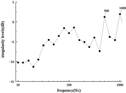
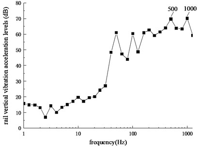
Through the frequency domain transformation for the above-mentioned irregularity-mileage curve, the frequency spectrum diagram of irregularity levels can be obtained, as shown in Fig. 2. It can be seen that the main passing frequencies on the section are 500 Hz and 1000 Hz. Due to the measured corrugation appears on the tangential section and the passing frequencies are in the range of 400-1200 Hz, which is similar to the line condition and frequency range of rail corrugation caused by Pinned-Pinned resonance of track structure, therefore, it is considered that the corrugation on this section is roaring rail corrugation.
Fig. 2Frequency spectrum of irregularity levels
3. Cause analysis of corrugation
In this section, the causes and development characteristics of rail corrugation are studied from the perspectives of modal analysis of track structure model and dynamic analysis of vehicle-track space coupled model, so as to provide reference for the prevention and control of rail corrugation.
3.1. Modal analysis
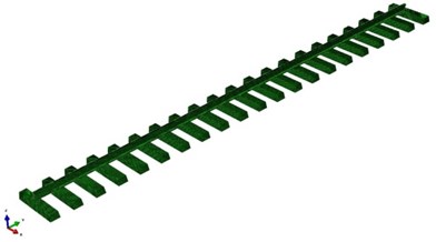
The three-dimensional solid model of track structure is established by using the finite element software ABAQUS, as shown in Fig. 3. The rail is 60 kg/m and the sleeper is the reinforced concrete sleeper. The fastener is simulated by spring-damper elements and the parameters are shown in the reference [21]. Because of the symmetry of the tangential track structure, only the half of track structure is considered in the modeling process. The symmetrical constraints are set at the symmetrical surface of the sleeper, and both ends of the rail and the bottom surface of the sleeper are fixed. In order to eliminate the influence of boundary conditions of track structure and avoid excessive calculation amount of the model, the length of track structure is taken as 20 span sleeper spacings [22].
Fig. 3Finite element model of track structure
Through the modal analysis of the finite element model of track structure, the vibration modes of track structure corresponding to the characteristic frequencies, which are close to the passing frequencies of measured rail corrugation, can be obtained, as shown in Fig. 4.
Fig. 4Vibration modes of track structure
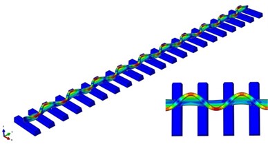
a) Vibration mode at the frequency of 513.7 Hz
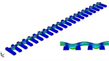
b) Vibration mode at the frequency of 1050.0 Hz
It can be seen from Fig. 4 that the characteristic frequency of 513.7 Hz is close to the measured corrugation passing frequency of 500 Hz, which corresponds to the transverse bending vibration of track structure. The vibration amplitude reaches the smallest at the position of fasteners and the largest at the position of mid-spans. The wavelength of the vibration mode is equal to the length of two span sleeper spacings. Therefore, it can be determined that the vibration mode at the frequency of 513.7 Hz is the transverse Pinned-Pinned resonance mode of track structure. The characteristic frequency of 1050.0 Hz is close to the measured corrugation passing frequency of 1000 Hz, which corresponds to the vertical bending vibration of track structure. The vibration amplitude reaches the smallest at the position of fasteners and the largest at the position of mid-spans. The wavelength of the vibration mode is equal to the length of two span sleeper spacings. Therefore, it can be determined that the vibration mode at the frequency of 1050.0 Hz is the vertical Pinned-Pinned resonance mode of track structure. It can be obtained from the above analysis that the Pinned-Pinned resonance is the main reason for the occurrence of rail corrugation on the measured line. Besides, the modal analysis results of the finite element model of track structure have characteristic frequencies close to passing frequencies of measured corrugation, which can also verify the rationality of the finite element model of track structure.
3.2. Dynamic analysis
3.2.1. Establishment of vehicle-track space coupled model
Based on the actual situation of the measurement line, the vehicle-track space coupled dynamic model is established by using the multi-body dynamics software UM (Universal Mechanism), which can consider the coupled relationship in three directions of space. The vehicle model adopts the Metro Type A vehicle and the values of each parameter are shown in Table 1. The track model adopts the flexible track model, which simulates the fastener part as Bushing force elements and the rail as a Timoshenko beam considering the shear deformation. It can reflect the influence of high-frequency vibration very well and is applicable to the research of rail corrugation. The parameter values of track structure are shown in Table 2. The Kik-Piotrowski model is adopted as the wheel-rail contact model, which uses the virtual penetration principle to solve the wheel-rail normal contact problem and relies on Kalker simplification theory to solve the wheel-rail tangent contact problem [23]. For the normal contact, the equations are as follows:
where is normal force, is Young’s modulus, is normal rigid penetration amount between wheel and rail, is Poisson’s ratio of materials, is the coordinate of front or rear edge of contact patch, , is interpenetrating function of contour, is rolling radius of wheel at contact point, is maximum compressive stress, is virtual penetration amount between wheel and rail.
For the tangential contact, according to the improved FASTSIM algorithm, the distribution forms of the tangential stress are derived as follows:
where , , are the longitudinal, transverse and spin creepages, is the elastic parameter value. The creep forces and can be calculated by integrating Eq. (3) and Eq. (4) in the contact patch, as shown below:
In addition to the creep forces mentioned above, there is also a torque around the axis between wheel and rail. However, compared with the rotation torque generated by the difference between the longitudinal creep forces of left and right wheels, the is too small, so it is ignored.
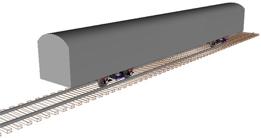
Based on the vehicle model, track model and wheel-rail contact model, the vehicle-track space coupled model is established, as shown in Fig. 5.
Table 1Vehicle parameters
Parameter | Value |
Frame mass / kg | 4 420 |
Vehicle mass / kg | 26 040 |
Primary spring vertical stiffness / (N/m) | 1.3×10⁶ |
Primary spring transversal stiffness / (N/m) | 547 000 |
Primary spring longitudinal stiffness / (N/m) | 547 000 |
Primary spring vertical damping / (Ns/m) | 2 400 |
Secondary spring vertical stiffness / (N/m) | 270 000 |
Secondary spring transversal stiffness / (N/m) | 115 000 |
Secondary spring longitudinal stiffness / (N/m) | 115 000 |
Secondary spring vertical damping / (Ns/m) | 23 000 |
Moment of inertia of bogie yawing / (kg·m2) | 3 551 |
Moment of inertia of bogie rolling / (kg·m2) | 1 576 |
Moment of inertia of bogie pitching / (kg·m2) | 4 902 |
Moment of inertia of body yawing / (kg·m2) | 1.1×10⁶ |
Moment of inertia of body rolling / (kg·m2) | 58 800 |
Moment of inertia of body pitching / (kg·m2) | 1.1×10⁶ |
Length of vehicle / m | 22.0 |
Width of vehicle / m | 3.0 |
Bogie wheelbase / m | 2.5 |
Length between bogie pivot centers / m | 15.7 |
Table 2Track structure parameters
Parameter | Value |
Young’s modulus of rail / MPa | 2.059×10⁵ |
Poisson’s ratio of rail | 0.3 |
Rail density / (kg/m3) | 7 800 |
Vertical stiffness of fastener / (MN/m) | 40.73 |
Transversal stiffness of fastener / (MN/m) | 8.79 |
Longitudinal stiffness of fastener / (MN/m) | 8.79 |
Vertical damping of fastener / (Ns/m) | 6 361.29 |
Transversal damping of fastener / (Ns/m) | 1 927.96 |
Longitudinal damping of fastener / (Ns/m) | 1 927.96 |
Spacing of fastener / m | 0.6 |
Young’s modulus of sleeper / MPa | 3.25×10⁴ |
Poisson’s ratio of sleeper | 0.24 |
Sleeper density / (kg/m3) | 2 400 |
Foundation support stiffness / (MN/m) | 170 |
Foundation support damping / (Ns/m) | 3.1×10⁴ |
Fig. 5Vehicle-track space coupled model diagram
3.2.2. Verification and analysis of the model
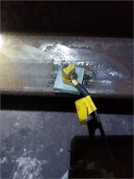
In order to ensure the correctness of the subsequent calculation, this section verifies the established vehicle-track space couple model. The measured data is the rail vertical vibration acceleration on the metro line. Two sensors are arranged on the section of the measuring point, which are respectively located on both sides of the upper surface of rail bottom. The INV 3060 s acquisition instrument is used for data acquisition with the data sampling frequency of 1024 Hz and speed working condition of 60 km/h, and the software DASP-V10 is used for data analysis. The layout picture of the measuring point is shown in Fig. 6.
Fig. 6Layout picture of the measuring point
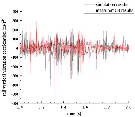
Based on the vehicle-track space coupled model, the measured corrugation irregularity is applied as the initial rail surface irregularity, and then the simulation is carried out. Extract the rail vertical vibration acceleration data in the section of the measuring point, and compare it with the measured data, as shown in Fig. 7. The outcome shows that the simulation results are in good agreement with the measurement results, which verifies the validity of the model.
Fig. 7Comparison of simulation and measurement results
Further, the corresponding one-third octave curve can be obtained by frequency domain transformation for the time history curve of rail vertical vibration acceleration of simulation results, as shown in Fig. 8.
It can be seen from Fig. 8 that the rail vertical vibration acceleration levels have higher amplitudes at the central frequencies of 500 Hz (69.7 dB) and 1000 Hz (70.1 dB), which are consistent with passing frequencies of measured corrugation, and the one-third octave band width corresponding to the central frequency of 500 Hz is 447-562 Hz and the one-third octave band width corresponding to the central frequency of 1000 Hz is 891-1120 Hz, which are in the frequency range of Pinned-Pinned resonance of track structure. Therefore, it can be concluded that rail corrugation on the measured section is roaring rail corrugation caused by Pinned-Pinned resonance of track structure.
Fig. 8Frequency spectrum of rail vertical vibration acceleration levels
4. Development characteristics of corrugation
4.1. Development characteristics of corrugation under different sleeper spacings
Based on the vehicle-track space coupled dynamic model, the rail vertical vibration accelerations with sleeper spacings of 500 mm, 550 mm, 600 mm, 650 mm and 700 mm are calculated respectively, and the frequency domain transformation is carried out to obtain the corresponding one-third octave curves as shown in Fig. 9.
Fig. 9Frequency spectrum of rail vertical vibration acceleration levels
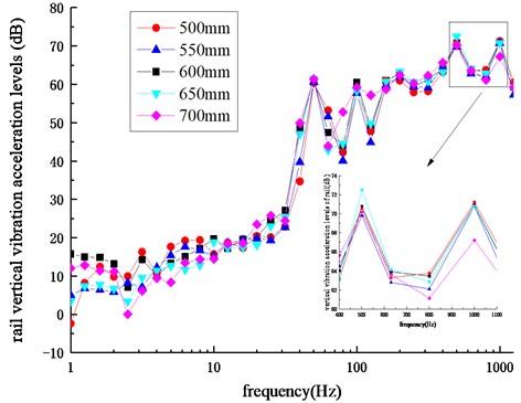
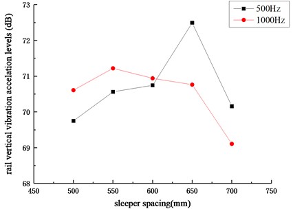
According to Fig. 9, the change trends of rail vertical vibration acceleration levels is basically the same under different sleeper spacings and the amplitudes of rail vertical vibration acceleration levels at the center frequencies of 500 Hz and 1000 Hz are higher than others. The rail vertical vibration acceleration levels corresponding to 500 Hz and 1000 Hz under different sleeper spacings are shown in Fig. 10. The analysis shows that for the center frequency of 500 Hz, the rail vertical vibration acceleration level increases first and then decreases with the increase of sleeper spacings. The maximum value appears when the sleeper spacing is 650 mm and the minimum value appears when the sleeper spacing is 500 mm. As for the center frequency of 1000 Hz, the rail vertical vibration acceleration level also increases first and then decreases with the increase of sleeper spacings. The maximum value appears when the sleeper spacing is 550 mm and the minimum value appears when the sleeper spacing is 700 mm. It can be seen that by changing the sleeper spacing, the rail vertical vibration acceleration level can be changed significantly, indicating that the appropriate sleeper spacing (about 700 mm) can effectively control the generation and development of rail corrugation.
Fig. 10Rail vertical vibration acceleration levels
4.2. Development characteristics of corrugation under different operating speeds
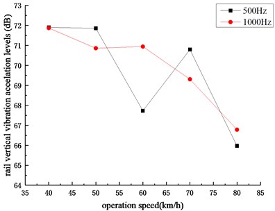
Set the sleeper spacing as 600 mm and carry out the time-domain calculation and frequency domain transformation for the rail vertical vibration acceleration levels under operation speeds of 40 km/h, 50 km/h, 60 km/h, 70 km/h and 80 km/h, respectively. The corresponding one-third octave curves are shown in Fig. 11.
Fig. 11Frequency spectrum of rail vertical vibration acceleration levels
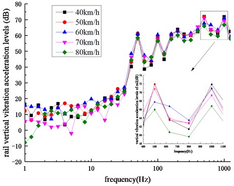
It can be seen from Fig. 11 that under different operating speeds, the change trends of rail vertical vibration acceleration levels are almost unanimous and the amplitudes of rail vertical vibration acceleration levels at the center frequencies of 500 Hz and 1000 Hz are higher than others. The rail vertical vibration acceleration levels corresponding to 500 Hz and 1000 Hz under different operation speeds are shown in Fig. 12. It can be obtained that for the central frequency of 500 Hz, the rail vertical vibration acceleration level first decreases, then increases, and finally decreases with the increase of operation speeds. The maximum value appears when the operation speed is 40 km/h and the minimum value appears when the operation speed is 80 km/h. As for the central frequency of 1000 Hz, the rail vertical vibration acceleration level also decreases first, then increases and finally decreases with the increase of operation speeds, and the increase degree of the middle part is relatively small. The maximum value appears when the operation speed is 40 km/h and the minimum value appears when the operation speed is 80 km/h. It can be seen that by changing the operation speed, the rail vertical vibration acceleration level can be changed significantly, which shows that the appropriate operation speed (about 80 km/h) can effectively inhibit the generation and development of rail corrugation.
Fig. 12Rail vertical vibration acceleration levels
5. Conclusions
Taking the rail corrugation on the tangential section as the research object, through modal analysis and dynamic analysis, the causes and development characteristics of rail corrugation are studied. The following conclusions can be obtained:
1) The line condition and passing frequency range of measured corrugation are similar to those of corrugation induced by Pinned-Pinned resonance of track structure. It is preliminarily considered that the corrugation type occurred on measured section is roaring rail corrugation.
2) The modal analysis of track structure model shows that the vibration mode at the frequency of 513.7 Hz is the transverse Pinned-Pinned resonance mode of track structure and the vibration mode at the frequency of 1050.0 Hz is the vertical Pinned-Pinned resonance mode of track structure. The dynamic analysis of vehicle-track space coupled model shows that the rail vertical vibration acceleration levels have higher amplitudes at the central frequencies of 500 Hz and 1000 Hz, which are 69.7 dB and 70.1 dB respectively, and the one-third octave band widths corresponding to the above center frequencies are in the frequency range of Pinned-Pinned resonance of track structure. The results of modal analysis and dynamic analysis all contain characteristic frequencies close to passing frequencies of measured corrugation, and these frequencies correspond to the Pinned-Pinned resonance of track structure, therefore, it can be determined that the rail corrugation on the measured line is roaring rail corrugation caused by Pinned-Pinned resonance of track structure.
3) The changing trends of rail vertical vibration acceleration levels under different sleeper spacings and operation speeds are basically the same and the amplitudes of rail vertical vibration acceleration levels at the center frequencies of 500 Hz and 1000 Hz are higher than others. With the increase of the sleeper spacing and operation speed, the variation trends of rail vertical vibration acceleration levels at 500 Hz and 1000 Hz are almost unanimous. By changing the sleeper spacing and operating speed, the rail vertical vibration acceleration level can be significantly changed, which shows that the appropriate sleeper spacing (about 700 mm) and operating speed (about 80 km/h) can effectively control the generation and development of rail corrugation.
References
-
Ngai K. W., Ng C. F. Structure-borne noise and vibration of concrete box structure and rail viaduct. Journal of Sound and Vibration, Vol. 255, Issue 2, 2002, p. 281-297.
-
Xia H., Zhang N., Cao Y. M. Experimental study of train-induced vibrations of environments and buildings. Journal of Sound and Vibration, Vol. 280, Issues 3-5, 2005, p. 1017-1029.
-
Liu W. F., Liu W. N., Wu Z. Z., et al. Experimental study of the governance of rail corrugation of shear damper fastener in Beijing subway. Journal of Mechanical Engineering, Vol. 51, Issue 21, 2015, p. 73-79.
-
Zhou L. Experimental study of corrugation measures for the curve track in Shanghai. Urban Mass Transit, Vol. 12, Issue 9, 2009, p. 62-66.
-
Yan Y. Z. Analysis on corrugation of curve rail with small radius of Guangzhou Metro Line 5. Urban Mass Transit, Vol. 14, Issue 6, 2011, p. 55-57+63.
-
Grassie S. L. Rail corrugation: characteristics, causes, and treatments. Proceedings of the Institution of Mechanical Engineers, Part F: Journal of Rail and Rapid Transit, Vol. 223, Issue 6, 2009, p. 581-596.
-
Böhmer A., Klimpel T. Plastic deformation of corrugated rails-A numerical approach using material data of rail steel. Wear, Vol. 253, Issue 1, 2002, p. 150-161.
-
Correa N., Oyarzabal O., Vadillo E. G., et al. Rail corrugation development in high speed lines. Wear, Vol. 271, Issues 9-10, 2011, p. 2438-2447.
-
Carlberger A. Simulation of Rail Corrugation Growth on Curves. Chalmers University of Technology, Gothenburg, Sweden, 2016.
-
Ilias H. The influence of railpad stiffness on wheelset/track interaction and corrugation growth. Journal of Sound and Vibration, Vol. 227, Issue 5, 1999, p. 935-948.
-
Tanaka H., Miwa M. Modeling the development of rail corrugation to schedule a more economical rail grinding. Proceedings of the Institution of Mechanical Engineers, Part F: Journal of Rail and Rapid Transit, Vol. 234, Issue 4, 2020, p. 370-380.
-
Wang B. K., Xie Y. B. Mechanism of short wavelength corrugation of rail surface. Tribology, Vol. 21, Issue 5, 2001, p. 375-378.
-
Wen Z. F., Jin X. S. Analysis of rolling contact and rail corrugation under non-steady state loading. Tribology, Vol. 27, Issue 3, 2007, p. 252-258.
-
Li X. Study on the Mechanism of Rail Corrugation on Subway Track. Southwest Jiaotong University, Chengdu, 2012.
-
Jin X. S., Wen Z. F. Effect of discrete track support by sleepers on rail corrugation at a curved track. Journal of Sound and Vibration, Vol. 315, Issues 1-2, 2008, p. 279-300.
-
Jin X. S., Wen X. S., Wang K. Y. Effect of track irregularities on initiation and evolution of rail corrugation. Journal of Sound and Vibration, Vol. 285, Issues 1-2, 2005, p. 121-148.
-
Cai X. P., Zhong Y. L., Guo L. W., et al. Experimental study on effect of rail corrugation on structure vibration in Egg fastener zone. Journal of Vibration, Measurement and Diagnosis, Vol. 39, Issue 2, 2019, p. 382-388+448-449.
-
Yu M., Wang W. D., Liu J. Z., et al. The transient response of high-speed wheel/rail rolling contact on “roaring rails” corrugation. Proceedings of the Institution of Mechanical Engineers, Part F: Journal of Rail and Rapid Transit, Vol. 233, Issue 10, 2019, p. 1068-1080.
-
Wu B. W., Chen G. X., Lv J. Z., et al. Generation mechanism and remedy method of rail corrugation at a sharp curved metro track with Vanguard fasteners. Journal of Low Frequency Noise, Vibration and Active Control, Vol. 39, Issue 2, 2020, p. 368-381.
-
Lei Z. Y., Wang Z. Q. Generation mechanism and development characteristics of rail corrugation of cologne egg fastener track in metro. KSCE Journal of Civil Engineering, Vol. 24, Issue 6, 2020, p. 1763-1774.
-
Lei Z. Y., Wang Z. Q., Li L., et al. Rail corrugation characteristics of the common fastener in Metro. Journal of Tongji University (Natural Science), Vol. 47, Issue 9, 2019, p. 1334-1340.
-
Wei W. High Frequency Vibration of Railway Track and Wheel. Southwest Jiaotong University, Chengdu, 1997.
-
Piotrowski J., Kik W. A simplified model of wheel/rail contact mechanics for non-Hertzian problems and its application in rail vehicle dynamic simulations. Vehicle System Dynamics, Vol. 46, Issues 1-2, 2008, p. 27-48.
About this article

The paper is supported by the National Natural Science Foundation of China (11772230).
