Abstract
Prestressed concrete continuous beam-arch composite bridge with concrete-filled steel tube is a new type of bridge developed in recent years. It has the characteristics of strong spanning ability and large in-plane stiffness, but the lateral stiffness of the arch ribs for this type of bridge is relatively weak. In order to effectively improve the construction quality and structure stability, and optimize the mechanical properties, and in addition of realize the design of large span continuous beam-arch composite bridge, a comprehensive safety assessment of the Liuxi River bridge during construction and serving stages located in China was conducted in this paper. The results show that the bridge had favorable safety margin during the construction and severing stages. The outcomes of this study can provide technical support for the safety and smooth implementation of the bridge’s safeguard, which has important theoretical significance and engineering application value.
Highlights
- Safety assessment of construction and servicing stages of bridge was comprehensively analyzed
- Particularity of multiaxial internal force state of the arch foots under combined actions was discussed
- Displacement of the arch rib is similar to that of the beam
1. Introduction
Concrete-filled steel tube arch bridge is a steel-concrete composite bridge using steel tubes filled with concrete as the arch ribs. Prestressed concrete beam-arch composite bridge with concrete-filled steel tube is a new type of bridge structure developed in recent years [1]. From the analysis of its stress characteristics, the internal force generated by the external load in the beam and arch is mostly converted into the internal force of the self-balancing system, and the structural stress indicates that the arch is mainly in compression and beam in tension [2]. This type of bridge system can give full play to the advantages of arch and beam in terms of stress, and present a beautiful appearance and excellent technical and economic indicators.
Continuous beam-concrete-filled steel tube arch composite bridge has the characteristics of strong spanning ability and large structural in-plane stiffness, but the transverse stiffness of the ribs for the bearing arches is relatively weak [3]. As the main compression member, arch rib is easy to lose stability, especially the out-plane stability, that is, the structural instability. In addition, due to the consolidation of the arch rib and the beams, the arch foots and the fulcrums in the beam body tend to produce a large negative bending moment [4].
In order to effectively improve the construction quality and structure stability, and optimize the mechanical properties, and in addition of realize the design of large span continuous beam-arch composite bridge, a comprehensive safety assessment of the Liuxi River bridge located in China during construction and serving stages was conducted in this paper. The Liuxi River Bridge is composed of a continuous box-girder and concrete filled steel tubes arch ribs, which is the largest bridge along the railway. The steel tube and infilled concrete were modeled based on the equivalence theory. The synergistic interactions between the main girder and composite arches subjected to the high speed rail loads was complicated and undiscovered, which was comprehensively analyzed and presented. Discussion on the particularity of multiaxial internal force state of the arch foots under combined actions of axial, shear, bending and torque loads also provided the basis for the optimization of the bridge performance. The outcomes of this study can provide technical support for the safety and smooth implementation of the bridge’s safeguard, which has important theoretical significance and engineering application value.
2. Method
2.1. Bridge description
Liuxi river bridge is located in Baiyun district of Guangzhou city, China, with the central mileage of DIIK11+530.208. The starting and terminating mileage of the bridge is DK8+484.56 and DK14+575.855, respectively. The total length of the bridge is 6091.3 m, with 171 piers. The continuous beam-arch composite bridge (90 m +180 m +90 m) is loacted at DK11+507.99 and crosses the Liuxi river, in which the piers 85# and 86# were located in the Liuxi river, as shown in Fig. 1.
Fig. 1Layout plan of 90+180+90m extra-large bridge on Liuxi river

2.2. Finite element model
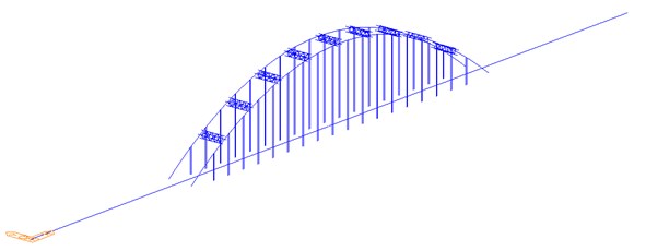
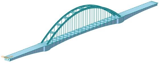
According to the layout and geometrical dimensions of the structure, the structures above the foundations were isolated for analysis. The main girder, arch ribs and transverse braces of the bridge are simulated using beam elements. The variable section of the main girder is realized by setting beam element variable section group. The suspender is simulated by truss element. The whole bridge is divided into 840 nodes and 1129 elements. The main beam element is 4.5 m in size, the arch rib element length is 1.8 m-9 m and the boom element length is 11 m-37.5 m. The beam system model is shown in Figure 2, and the finite element model is shown in Fig. 3.
Fig. 2Structure drawing of bar system
The steel tube is filled with C55 non-shrinkage concrete, with 3.60×10⁴ MPa. Allowable stress of the C55 concrete: 14.8 MPa, 18.5 MPa, 2.97 MPa. The main girder is made of C55 high performance concrete, with 37.0 MPa, 3.3 MPa, 3.60×10⁴ MPa. The arch rib steel tube, web and transverse brace are made of Q345q-D steel, and the rest are made of Q235q-D steel. PES (FD) 7-61 low-stress anticorrosive cable is used for the suspender, with 1670 MPa and 2.0×10⁵ MPa. Pretended cables use low relaxation high strength strand, the standard strength is 1860 MPa, the diameter is 15.2 mm, the cross-sectional area of the cable is 140 mm2, and 1.95×10⁵ MPa.
Concrete material bulk weight is 26.5 kN/m3, and the steel bulk weight is 78.5 kN/m3. The constant load including rail, sleeper, ballast, protective layer, waterproof layer, triangular cushion, ballast retaining wall, sidewalk, guardrail, etc. (the minimum ballast thickness at the bottom of the rail is designed as 30 cm), which is total of 142.9 kN/m. The shrinkage and creep of concrete-filled tube are reduced appropriately.
Vertical live load of train is adopted for longitudinal calculation, and 90 % for double lines. Transverse sway force is applied as a concentrated load with a value of 100 kN, which is acted at the most unfavorable position that located on the top surface of the rail in the middle line along the horizontal direction.
Temperature load: calculated and adopted according to the basic specifications for design of railway bridges (TB10002.1), and design specifications for reinforced concrete and prestressed concrete structures of railway bridges (TB10002.3-2005). The overall temperature rise of the structure is +20 ℃ and the overall temperature drop is –20 ℃.
Nonlinear temperature rise of roof of main girder is +5 ℃; the temperature difference between arch rib and main beam is ±10 ℃. The temperature difference between the boom and the main beam is ±15 ℃. The basic wind pressure is 1000 Pa.
Fig. 3Structure diagram of the whole bridge
3. Results
3.1. Continuous beam
Based on the calculation results of the continuous beam in the construction stage and the servicing stage, the comparative analysis of the calculation results of internal forces, stresses and displacements of the main beam in each stage is carried out. The analysis results are shown in Table 1.
It is known that:
Axial force: there is little change in axial force in each stage of construction, and the axial force in serving stage is less than that in construction stage, and the additional load has little influence on the axial force.
Shear force: barely change was found in the shear force of the hanger, arch hanger and the primary tension hanger. When the shear force of bridge deck system is increased during construction, the shear force in servicing stage is higher than that in construction stage, and the additional load has little influence on the shear force.
Bending moment: negative bending moment increases in the construction stage of the hoisting arch rib and bridge deck system, decreases in the two tension suspensions, and increases in the serving stage in comparison with the construction stage. The positive bending moment decreases in the hoisting of arch rib, bridge deck construction and secondary tension, increases in the serving stage compared with the construction stage, and decreases in the positive bending moment under additional load.
Stress: the stress on the upper edge decreases with the progress of the construction phase, increases during the servicing phase compared with the construction phase, and the additional load increases the stress on the upper edge.
The stress of lower edge decreases with the construction stage, increases with the servicing stage, and increases with the additional load.
Vertical displacement: the construction of bridge deck system causes the continuous beam downward torsion to increase, the two tensioning suspender causes the continuous beam downward torsion to decrease, the servicing phase is more downward torsion than the construction phase, and the additional load action increases downward torsion.
Table 1Continuous beam results
Stage | Internal force | Stress | Displacement | |||||
Axial force (kN) | Shear force (kN) | Positive bending moment (kN·m) | Negative bending moment (kN·m) | Upper margin (MPa) | Lower margin (MPa) | Vertical displacement (mm) | ||
Construction | Demolition of hanger | –429069 | 67958 | –354782 | 80264 | –12.5 | –15.8 | –84.02 |
Hoisting arch rib | –427616 | 67959 | –406286 | 68163 | –11.5 | –15.2 | –86.52 | |
A tension | –427125 | 66676 | –369536 | 69126 | –11.7 | –14.7 | –73.33 | |
Bridge construction | –429849 | 75823 | –679712 | 45844 | –10.7 | –14 | –104.78 | |
The second boom | –429274 | 75188 | –629627 | 34424 | –10.6 | –13.5 | –86.99 | |
Servicing | Main load condition | –415977 | 85337 | –947976 | 181027 | –12.5 | –15.6 | –125.86 |
Main + additional load | –416023 | 85957 | –994431 | 150874 | –13.3 | –16.1 | –143.35 | |
3.2. Concrete-filled steel tube arch rib
Based on the calculation results of arch rib in construction stage and servicing stage, this section conducts comparative analysis of the calculation results of internal force, stress and displacement in each stage of arch rib. The analysis results are shown in Table 2.
It is known that:
Axial force: the axial force increases with the progress of the construction stage. In the servicing stage, the axial force increases under the main load condition compared with the construction stage, and the additional load reduces the maximum axial force.
Shear force: the shear force of arch rib is relatively small, and increases when the suspender is tensioned twice. The shear force in servicing stage is larger than that in construction stage, and the additional load has little impact on the shear force.
Bending moment: the negative bending moment increases in shear force when the suspender is tensioned twice, increases in servicing stage compared with construction stage, and decreases in negative bending moment under additional load. The positive bending moment increases during the bridge deck construction and the secondary tensioning of the suspender, increases during the servicing stage compared with the construction stage, and increases during the additional load.
Stress: the stress on the upper edge increases with the construction phase, and increases during the servicing phase compared with the construction phase. The lower edge stress increases with the construction stage, and the operating stage increases with the construction stage.
Vertical displacement: the construction of bridge deck system increases the deflection of arch rib, and the deflection increases in the servicing stage compared with the construction stage, and the additional load increases the deflection.
Table 2Arch rib results
Stage | Internal force | Stress | Displacement | |||||
Axial force (kN) | Shear force (kN) | Positive bending moment (kN·m) | Negative bending moment (kN·m) | Upper margin (MPa) | Lower margin (MPa) | Vertical displacement (mm) | ||
Construction | Demolition of hanger | –12346 | 479 | –4638 | 1789 | –5.2 | –7.9 | –14.8 |
Hoisting arch rib | –13529 | 527 | –5921 | 1654 | –5.5 | –9.2 | –16.3 | |
A tension | –19126 | 367 | –3110 | 2298 | –7.4 | –9.4 | –37.6 | |
Bridge construction | –20444 | 423 | –4994 | 2887 | –8.2 | –11.2 | –41.7 | |
The second boom | –32446 | 1075 | –5702 | 4315 | –15.6 | –14.7 | –51.17 | |
Servicing | Main load condition | –15390 | 1070 | –5420 | 4963 | –15.5 | –14.2 | –64.07 |
Main + additional load | –12346 | 479 | –4638 | 1789 | –5.2 | –7.9 | –14.8 | |
3.3. Suspenders
This section compares and analyzes the calculation results of internal forces, stresses and displacements of the boom in each stage based on the calculation results of the boom in the construction stage and the servicing stage. The analysis results are shown in Table 3.
Table 3Suspender results
Stage | Internal force (kN) | Stress (kN) | Displacement (mm) | |
Construction | A tension | 78.5 | 33.0 | –68.6 |
Bridge construction | 282.3 | 118.8 | –99.14 | |
The second boom | 329.5 | 138.7 | –81.86 | |
Servicing | Main load condition | –732.7 | 308.4 | –120.73 |
Main + additional load | 696.7 | 293.2 | –137.72 | |
It is known that:
Axial force: the axial force increases with the progress of the construction stage. In the servicing stage, the axial force increases under the main load condition compared with the construction stage, and the additional load reduces the maximum axial force.
Stress: the stress increases with the progress of the construction stage, and increases with the servicing stage compared with the construction stage. The additional load reduces the maximum stress.
Vertical displacement: due to the construction of bridge deck system, the deflection of the suspender increases; compared with the construction stage, the deflection increases during the servicing stage, and the additional load increases the deflection.
4. Conclusions
This paper carried out the safety assessment of construction and servicing stages, the synergistic interactions between the main girder and composite arches subjected to the high speed rail loads was comprehensively analyzed and presented. The particularity of multiaxial internal force state of the arch foots under combined actions of axial, shear, bending and torque loads was discussed to provide the basis for the optimization of the bridge performance. The conclusions can be drawn:
1) In the servicing stage, under the main load, the vertical deflection of the mid-span main beam is 125.86 mm.
2) In the servicing stage, under the most unfavorable combined action of the main load + additional load, the vertical deflection of the mid-span main beam is 143.35 mm.
3) The stress of the joint between the arch rib and the main beam at the arch foot is concentrated.
4) The displacement of the arch rib is similar to that of the beam.
5) After evaluation, the bridge is safe during construction and servicing.
References
-
He S., Fang Z., Mosallam A. S. Push-out tests for perfobond strip connectors with UHPC grout in the joints of steel-concrete hybrid bridge girders. Engineering Structures, Vol. 135, 2017, p. 177-190.
-
Yan B., Dai G. L., Guo W. H., Xu Q. Y. Longitudinal force in continuously welded rail on long-span tied arch continuous bridge carrying multiple tracks. Journal of Central South University, Vol. 22, Issue 5, 2015, p. 2001-2006.
-
Zou C., Wang Y., Moore J. A., Sanayei M. Train-induced field vibration measurements of ground and over-track buildings. Science of the Total Environment, Vol. 575, 2017, p. 1339-1351.
-
He S., Mosallam A. S., Fang Z., Liu L. Structural evaluation of steel-concrete joint with UHPC grout in single cable-plane hybrid cable-stayed bridges. Journal of Bridge Engineering, Vol. 24, Issue 4, 2019, p. 04019022.
About this article

