Abstract
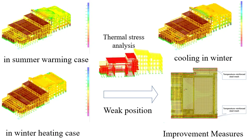
Waste incineration power station includes many functional structures, such as garbage discharge, storage, sorting and feeding units, boiler unit, tail gas treatment unit, leachate treatment unit, and coal storage unit. The structural forms of each part are different. Because of the particularity of garbage, structure units are required to be as close as possible and temperature joints should not be set up for the sake of possible leakage of exhaust gas or effluent liquor, so various structural units are integrated, which leads to the difficulty in structure design, and thermal stress cannot be neglected. In order to understand the effect temperature stress on main plant structures, a finite element model is established to study the distribution of thermal stress of the whole structure under three conditions: heating in summer, cooling in winter and heating in winter. It is found the influence of temperature on frame beam, column and steel space truss can be neglected, and the thermal stress on floor cannot be neglected [1]. The maximum stress is mainly distributed on both edges of floor along the longitude direction of structure. For those regions where stress concentration occurs, reinforcement bands or reinforcement mesh can be used to reduce the tensile stress. The analysis results show that this measure is effective and provides a reference for the design of the main structure of waste incineration power plant. This paper innovatively analyses the structure system of main workshop of refuse incineration power plant, which is composed of steel structure and concrete structure, and describes the skills and key points of complex system modeling. According to different seasons and heating temperature difference, the temperature stress on the surface of the structure is analyzed, which provides a reference for calculating degree stress and temperature difference of the similar structure system. The weak part of resistance to temperature stress in the structure system composed of concrete structure and steel structure is found out, and the corresponding solutions are put forward, which provides guidance for the construction of the main workshop of refuse incineration power station.
Highlights
- The object of analysis is the waste incineration power station with complex structure system.
- Analyze surface temperature stress of the structure according to different seasons and heating temperature difference.
- The weak resistance to temperature stress in the main workshop was found out through analysis.
- Proposed and verified the measures to solve the temperature stress in the main workshop.
1. Introduction
With the rapid development of economy and the constant expansion of population, the amount of domestic and industrial waste has increased sharply. Waste incineration is a better waste treatment scheme. Solid waste can be oxidized and decomposed sufficiently by incineration to reduce volume, remove toxicity, recover energy and manufacture by-products. It has the characteristics of thorough harmlessness, high degree of resource utilization and low secondary pollution. The heat generated by waste incineration can be used to generate electricity, realize the recycling of waste and save energy. Waste incineration power station is an important facility. A waste incineration power station mainly consists of two structural systems: RC structure and steel frame structure. Structures often face large temperature difference. According to the principle of thermal expansion and cold contraction, the structure systems of waste incineration power station will produce temperature cracks [2]. However, due to the particularity of waste, the structure system is required to be as close as possible, so it is not suitable to set temperature joints. This leads to the difficulty in structure design, because many structure units need to be integrated together. In order to ensure the safety of the structure system, it is necessary to analyze the temperature stress specially in the design.
Taking the comprehensive structure of refuse incineration power station composed of concrete structure and steel frame structure as an example, this paper summarizes the unfavorable temperature environment of the structure into three situations: summer heating, winter cooling and winter heating. According to H. J. Dai’s calculation formula [2], the corresponding temperature difference is calculated, and the temperature stress analysis is realized by SAP2000 software. This paper studies the stress of beam-column slab of main factory building under three conditions of summer heating, winter cooling and winter heating, finds out the location of stress concentration, and puts forward strengthening measures, and compares and analyses the temperature stress after strengthening.
2. Model establishment
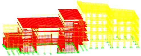
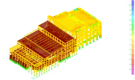
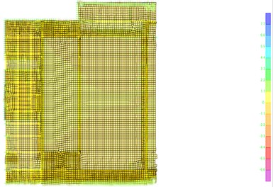
Concrete structure (the left side) is more complex, using PKPM for modeling, steel structure (the right side) using SAP2000 for modeling, through nosaCAD concrete PKPM model into SAP2000 model, and with steel structure model splicing, modal verification after merging joints, comparing the period before and after splicing. The complete model is shown in Fig. 1. The length, width and height of the main concrete workshop is 105.7 m, 79.5 m and 34.6 m respectively, and the length, width and height of the steel space truss structure is 76.4 m, 64.3 m and 44.9 m.
Fig. 1Analysis model of the main plant structure
3. Determine the temperature difference
Combined with the influencing factors of temperature variation, the comprehensive temperature variation () is determined according to the seasonal temperature variation and equivalent temperature variation of concrete shrinkage. The temperature reduction coefficient () is determined according to the relaxation coefficient (), plastic coefficient () and the reduction coefficient of stiffness due to crack. The calculated temperature variation () is derived from the temperature reduction coefficient and the comprehensive temperature variation. Then, the calculated temperature difference can be used to analyze the temperature effect on the structure. The calculated temperature variation () is given by:
where is the calculated temperature variation, is the comprehensive temperature variation, is the temperature reduction coefficient, is the plastic coefficient, is the relaxation coefficient ( is 0.5 here), and are local maximum and minimum temperatures, and is Elastic Conversion of Section Height.
Another method for calculating temperature variation is to use the difference between the maximum average temperature and the average temperature. Then, the unfavorable case is to use the larger value of temperature variation.
4. Analysis results and measures discussion
According to the local meteorological conditions where the plant is located, the temperature rises at 41 ℃ in summer and decreases at 19 ℃ in winter. When heating in winter, the equivalent analysis method is to cool the outer surface of the structure by 20 ℃.
4.1. Summer warming case
When the temperature rises to the highest level in summer, about 41 ℃, the stress on the top of the space truss connected with the main RC workshop is larger, which is about 73 MPa. The shear force of columns around corners of the main RC workshop is 3.16 N, 13.22 N, 2408.41 N and 1674.56 N respectively. The maximum tensile stress of the floor is 0.274 MPa and the maximum compressive stress is 0.926 MPa, which mainly distributes in the edges and the connection between the main RC workshop and the steel space truss.
Fig. 2Stress contour of the structure in summer warming case
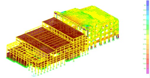
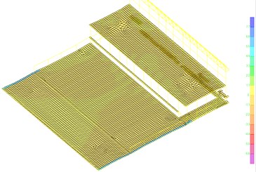
Fig. 3Stress distribution on floors of the main RC workshop in summer warming case
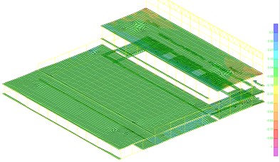
a) Stress distribution on top two floors
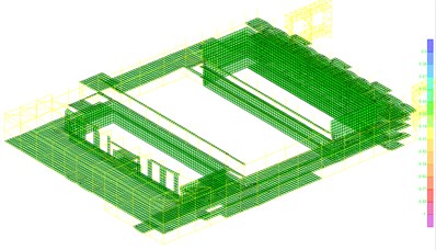
b) Stress distribution on rest floors
4.2. Cooling in winter
When the temperature reduces to the lowest level in winter, which is about –19 ℃, the stress on the top of the space truss connected with the main RC workshop is larger, which is about 33 MPa. The shear force of columns around corners of the main RC workshop is 1.47 N, 6.12 N, 1116.10 N and 1400.21 N respectively. The maximum tensile stress of the floor is 0.429 MPa and the maximum compressive stress is 0.127 MPa, which also mainly distributes in the edges and the connection between the main RC workshop and the space truss.
Fig. 4Stress contour of the structure for cooling in winter case
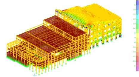
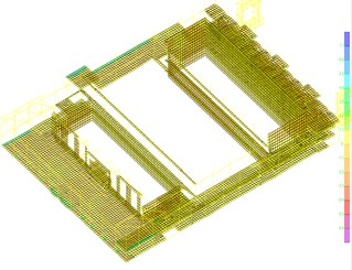
Fig. 5Stress distribution on floors of the main RC workshop for cooling in winter case
a) Stress distribution on top two floors
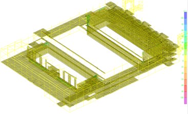
b) Stress distribution on rest floors
4.3. Winter heating
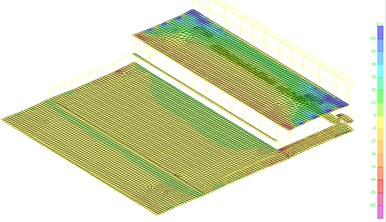
When heating in winter, the equivalent analysis method is to cool the outer surface of the structure by 20 ℃, it is found that the stress at the top of the space truss is larger, which is about 97 MPa. The shear force of the corner columns around the main RC workshop is 14.11 KN, 24.21 KN, 24.29 KN and 52.88 KN. The maximum tensile stress of the floor is 5.70 MPa and the maximum compressive stress is 1.73 MPa, which mainly distributes on both longitude edges and the connection between the main RC workshop and the space truss.
Fig. 6Stress contour of the structure in winter heating case
4.4. Improvement measures
In the case of heating in winter, the maximum tensile stress and compressive stress of the concrete main workshop floor are 5.70 MPa and 1.73 MPa, which are mainly distributed both longitude edges and the connection between the main RC workshop and the space truss, as shown in Fig. 7. In order to prevent the potential cracks of floors in above regions, post pouring zone, temperature reinforcement or carbon fiber sheet can be used. According to the economy and the complexity of construction technology, the temperature reinforcement bar is preferred. Temperature reinforcing bars are widely used at home and abroad. Referring to Chinese “Code for Concrete Structure Design” GB50010-2010, the concrete layout methods are as follows.
Fig. 7Stress distribution on floors of the main RC workshop in winter heating case
a) Stress distribution on top two floors
b) Stress distribution on rest floors
According to the analysis of the temperature stress distribution, the temperature stress on both sides of the board is larger, so the inner diameter of the two sides of the board is 6.5, and the distance between the two sides is 100. The width of the steel bar network is 3 meters (width according to the temperature stress beyond the standard range), and the length is the length of the board. Temperature reinforced steel bar and original steel bar penetration layout, the thickness of protective layer is 20 mm. Temperature stress reinforcement is used to resist restraint tension stress caused by shrinkage and temperature change of concrete in cast-in-place floor. Temperature reinforcement is arranged in the area shown in Fig. 8. Strengthened temperature reinforcement can effectively reduce the stress of floors to acceptable range. As shown in Fig. 9, when strengthened temperature reinforcement is used, the tensile stress of floors is reduced to 1.67 MPa.
Fig. 8Layout of the strengthened temperature reinforcement
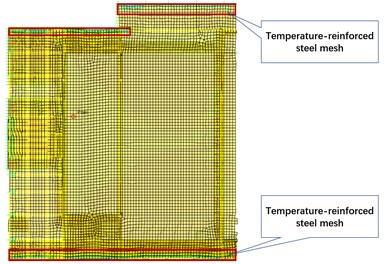
Fig. 9The tensile stress of floors after the strengthened temperature reinforcement is arranged
5. Conclusions
The following conclusions can be drawn from the analysis of temperature stress in the main plant structure of waste power station.
The effect of temperature on frame beams and columns can be neglected, but the effect on floors is greater, it cannot be neglected. Measures need to be taken to reduce the tensile stress caused by temperature.
The location of the maximum tensile stress produced by the temperature action on the floor mainly distributes in both longitude sides and the connection between the main RC workshop and the space truss.
Reinforcing steel bar band is set at the place where the tensile stress of floors is larger, which can effectively reduce the tensile stress of concrete caused by temperature action.
References
-
Zhao T. B. Temperature Stress Analysis of Super-Long Structures. M.S. Thesis, Zhengzhou University, Zhengzhou, China, 2003, (in Chinese).
-
Dai H. J. Research on Temperature-Dependent Response of Concrete Structure of Main Powerhouse of Large Thermal Power Plant. M.S. Thesis, Xi'an University of Architecture and Technology, Xi’an, China, 2011, (in Chinese).
-
Shan C., Liu W. Temperature stress analysis of prestressed concrete box girder with corrugated steel webs. Transactions of Tianjin University, Vol. 18, Issue 2, 2012, p. 97-103, (in Chinese).
-
Yan P. Research on temperature field and temperature stress of large span concrete cable-stayed bridge girder. Applied Mechanics and Materials, Vol. 178, Issue 181, 2012, p. 2075-2080, (in Chinese).
-
Liao Y. Y. Analysis and Control of Temperature Cracks in Super-Long Concrete Structures. M.S. Thesis, Hefei University of Technology, Hefei, China, 2012, (in Chinese).
-
Cui S. Temperature Stress Analysis and Control of Super-Long Structures. M.S. Thesis, Tongji University, Shanghai, China, 2007, (in Chinese).
-
Chen X. D. Environmental Temperature Effect of Extra-long Concrete Semi-basement Exterior Wall. M.S. Thesis, Tongji University, Shanghai, China, 2006, (in Chinese).
-
Harwood J. Temperature stress: reacting and adapting: lessons from poikilotherms. Annals of the New York Academy of Sciences, Vol. 1113, Issue 1, 2007, p. 52-57.
-
Zhao Jida, Xu Youlin, Huang Xiaokun, et al. Code for design of concrete structures (GB 50010-2010). Construction Science and Technology, Vol. 10, 2015, p. 28-30.
About this article

This work was supported by National Natural Science Foundation of China under Grant No. 10802104, and Fundamental Research Funds for the Central Universities of Project No. 2019CDCGJ013.
