Abstract
The paper presents a study dedicated to analyzing the sensitivity of structures with open contours to cracks. For this purpose, we analyze the particular case of the I-beam made by welding, for which we want to see how the frequencies of different modes of vibration change when a crack occurs in the weld joint between the web and the flange. The research is done using numerical simulations performed with the ANSYS program, from which the natural frequencies are obtained depending on the depth and extent of the crack. A large number of vibration modes and two types of boundary conditions are taken into account. We found that the frequency changes are small but still detectable and depend on the beam fixation mode. This makes it possible to detect cracks in the weld joint if the vibration modes where the decrease in frequency is significant are analyzed.
Highlights
- We present the frequency changes for an I-beam with a geometrical discontinuity between the web anf the flange.
- The frequency evolution for 12 vibration modes and two beam fixing conditions is presented.
- We recommend the modes that should be considered for structural health monitoring and indicat the optimum position of the accelerometer
1. Introduction
Monitoring the integrity of structures is a constant concern of researchers and practitioners for several decades. In most cases, global control methods are used, which are based on the analysis of the vibration signals of the monitored structure. The parameters that are monitored and which provide information about the integrity of the structure are the natural frequencies, mode shapes and curvatures, and less often modal damping. Damage detection techniques that use these modal parameters are available [1-5]. There are also techniques that consider the axial forces manifested in the beam that appear due to environmental conditions [6] or operational loads [7-9]. All the methods that use the vibrations are based on the deterministic link between the changes of the beam geometry and its modal parameters. Mathematical relationships that formalize this link are presented in the literature for a single [10-12] or multiple cracks [13, 14].
Although open cross-section beams are often used in engineering structures, there are few studies that address the detection of cracks by vibration analysis for these types of structural elements, see for instance [15]. The intention of the authors is to investigate the behavior of I-beams with longitudinal cracks by involving numerical methods since these have been proved as reliable and versatile [16]. In addition, these methods can highlight the small frequency changes that are expected, and which are difficult to be observed in the initial stage of research by experiments. However, we have developed methods to increase the accuracy of frequency estimation [17-19] and the procedures to compare the modal parameters in the healthy and damaged state [20], so that we appreciate that in a mature stage the method to detect longitudinal cracks in weld joints of the I-beams will work efficiently.
2. Materials and methods
The research focuses on finding the effect of a longitudinal crack on the natural frequencies of I-beams. To this aim, a steel beam with three different boundary conditions is taken into account in this study. It has the geometrical dimensions are indicated in Fig. 1.
Fig. 1The geometry and dimensions of the I-beam
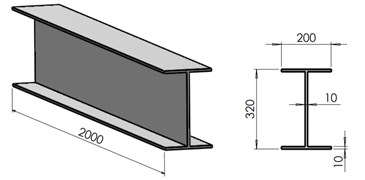
The relevant physical-mechanical properties extracted from the ANSYS library for a structural steel are: Mass density 7850 kg/m3, Young modulus 2·1011 N/m2, Poisson ratio 0.3, Tensile strength 470-630 MPa, Yield strength 355 MPa, and Min. elongation 20 %.
The two boundary conditions are as follows:
– Case 1: fixed at the bottom flange exterior surface (Fig. 2.a);
– Case 2: fixed at the median cross-section of the web (Fig. 2.b).
In case 2, for simplicity and without losing on information, we consider just the upper half of the I-beam.
The crack extends along the beam in longitudinal direction and is located in the corner weld joint between the flange and the web of the beam as presented in Fig. 3.
Fig. 2The boundary conditions considered in this research
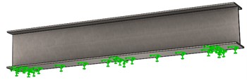
a)
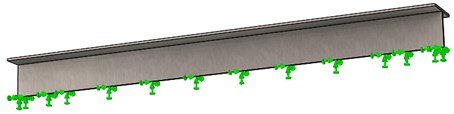
b)
Fig. 3The I-beam and a zoom on the crack location, highlighting it dimensions
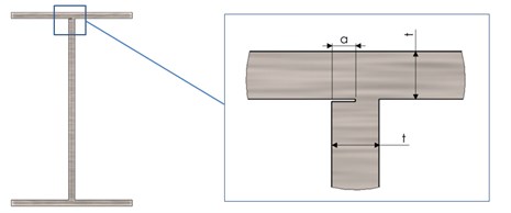
We consider 5 crack scenarios and study the effect of the different crack depths, starting with the crack depth 1 mm and further increasing it with a step of 1 mm until it reaches the depth 5 mm. The crack starts always from the exterior web surface of the I-beam, as illustrated in Fig. 3.
In order to obtain the natural frequencies of the healthy and damaged structure, a modal study has been carried out. The boundary conditions for the I-beam are imposed by applying the fixed support constraint as indicated in Fig. 2, first at the flange and secondly on the cross-section located at the mid of the web.
The intact beam was meshed by using hexahedral elements of 5 mm size, see Fig. 4(a). It results a model with 113936 elements and 623810 nodes. For the beam with a crack, illustrated in Fig. 4(b), the resulted mesh is even finer because the elements are deformed in the interface between the intact beam and damage boundary.
The dynamic behavior of the I-beam was studied by means of the ANSYS software. For the healthy beam and the beam with cracks of different depths we perform a modal analysis and determine the natural frequencies and mode shapes for the first thirteen vibration modes. The aim is to find if a sufficient frequency drop is obtained in order to indicate the crack and in which modes the biggest drop is obtained and qualify for the structural health monitoring.
Fig. 4A zoom on the left beam end for the intact beam a) and the damaged beam b), highlighting the prismatic element’s distribution
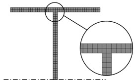
a)
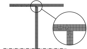
b)
3. Results and discussions
The simulation results presented in this section are processed in order to become relevant. This means we had to check the similarity of the vibration modes because the software assigns mode numbers according to the natural frequencies in ascending order, which is unsuitable for this analysis. Therefore, we checked the shape for each vibration mode and reordered these to ensure coherence. The frequencies acquired for the healthy beam and the beam with cracks are presented in Table 1 for the I-beam fixed at the flange and in Table 2 for the I-beam fixed at the mid of the web.
Table 1The frequencies for the I-beam fixed at the flange
Mode No. | (Hz) | (Hz) | (Hz) | (Hz) | (Hz) | (Hz) |
1 | 46.12 | 46.122 | 46.125 | 46.126 | 46.124 | 46.12 |
2 | 52.701 | 52.671 | 52.639 | 52.603 | 52.566 | 52.526 |
3 | 218.5 | 218.52 | 218.53 | 218.54 | 218.55 | 218.54 |
4 | 267.74 | 266.4 | 264.3 | 261.03 | 255.92 | 247.00 |
5 | 277.14 | 275.82 | 273.76 | 270.63 | 265.72 | 257.21 |
6 | 307.27 | 305.91 | 303.86 | 300.81 | 296.23 | 288.47 |
7 | 344.47 | 343.41 | 341.91 | 339.77 | 336.65 | 331.44 |
8 | 399.75 | 398.67 | 397.25 | 395.38 | 392.84 | 388.87 |
9 | 461.9 | 460.85 | 459.56 | 457.98 | 456.04 | 453.27 |
10 | 524.46 | 522.27 | 518.95 | 514.03 | 506.66 | 494.91 |
11 | 534.6 | 533.52 | 532.3 | 530.92 | 529.42 | 527.57 |
12 | 614.58 | 613.44 | 612.15 | 610.69 | 608.87 | 594.72 |
13 | 670.89 | 664.29 | 654.46 | 640.49 | 621.05 | 592.80 |
We observe from Table 1 that the first three and several superior modes are less sensitive to crack, while others attain big frequency drops even for a small crack depth. These latter vibration modes belong to the group characterized by the displacement of the flange and can be best used for structural health monitoring. The most relevant are modes five, six respectively twelve and thirteen, which all attain a bigger frequency decrease that 20 Hz for the longitudinal crack with depth 5 mm. In the mode thirteen the frequency decrease is 5 Hz even for the crack depth 1 mm, which is easily measurable.
The results presented in Table 2 lead to a different conclusion. We observe that here just the first three vibration modes are less sensitive to crack, while all superior modes attain big frequency drops. Therefore, all superior modes are qualified for structural health monitoring.
A comprehensive view on the normalized natural frequency evolution with the crack depth is presented in Fig. 5. The normalization is obtained by dividing the frequencies for the damaged beams with the frequency of the undamaged beam for the corresponding mode, see for instance reference [6]. One can observe a quite similar evolution, the difference consisting of the level of the frequency drop.
Table 2The frequencies for the I-beam fixed at the mid of the web
Mode no. | (Hz) | (Hz) | (Hz) | (Hz) | (Hz) | (Hz) |
1 | 126.06 | 126 | 125.91 | 125.75 | 125.38 | 124.88 |
2 | 133.96 | 133.87 | 133.76 | 133.6 | 133.31 | 132.98 |
3 | 255.83 | 255.55 | 255.19 | 254.58 | 253.36 | 251.81 |
4 | 457.03 | 451.51 | 444.02 | 431.35 | 404.31 | 375.11 |
5 | 463.59 | 456.18 | 446.59 | 431.63 | 407.11 | 380.77 |
6 | 471.94 | 465.13 | 456.65 | 443.62 | 423.19 | 403.72 |
7 | 492.9 | 485.99 | 477.23 | 463.08 | 438.98 | 415.52 |
8 | 536.03 | 529.58 | 521.45 | 509.11 | 488.16 | 467.61 |
9 | 598.59 | 592.28 | 584.54 | 572.68 | 553.06 | 533.35 |
10 | 656.47 | 654.6 | 652.31 | 647.98 | 629.27 | 610.74 |
11 | 673.43 | 667.1 | 659.48 | 649.07 | 644.13 | 639.96 |
12 | 756.85 | 750.59 | 743.15 | 732.07 | 714.49 | 697.32 |
13 | 849.84 | 843.62 | 836.31 | 825.68 | 808.94 | 792.9 |
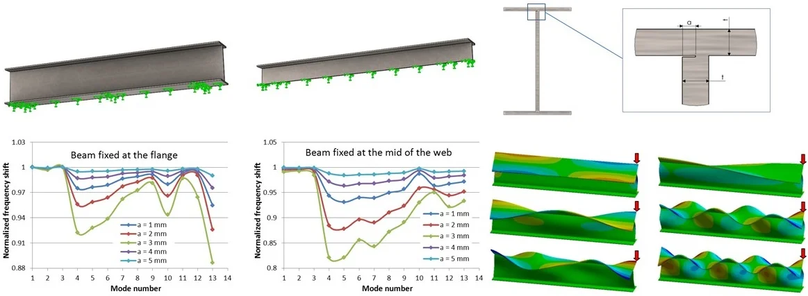
Fig. 5Normalized frequencies evolution with the crack depth for the two fixing conditions
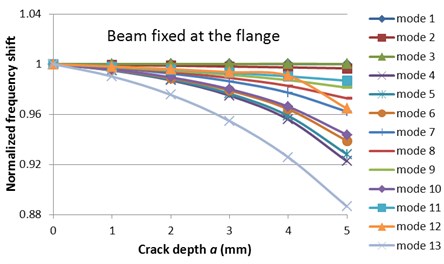
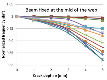
Fig. 6Normalized frequencies evolution with the mode number for the two fixing conditions
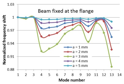
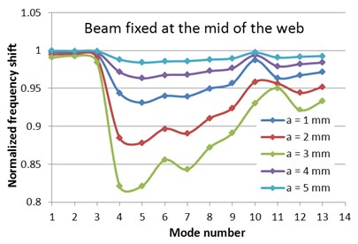
Fig. 6 shows the normalized frequency evolution with the mode number for the I-beam with fixed flange and the mid of the web, respectively. This figure shows once again the mode shapes for which a relevant frequency drop due to the crack is obtained. Because the fixing conditions can be more conveniently ensured at the flange, and the beam suffers frequency drops big enough to be read easily, we propose this approach for damage detection.
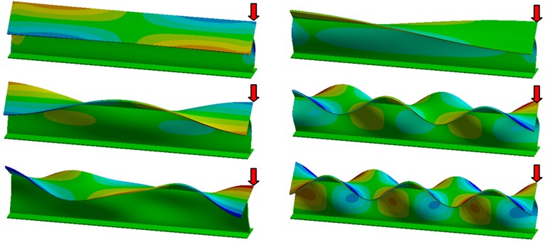
Fig. 7 illustrates six typical vibration mods with the beam fixed at the flange. In the figure the positions were the accelerometers should be located for best frequency readability is indicated by red arrows. It can be observed that the beam end is ideal to this aim and permits capturing signals with high amplitude for all considered modes. Obviously, depending on the vibration mode, some other locations are also available. The results of this study permit concluding the cracks in I-beams can be detected by vibration-based damage detection methods.
Fig. 7The shapes for the vibrating I-beam for six relevant modes
4. Conclusions
This paper presents a study made to find out if longitudinal crack occurring in the weld joint between the flange and the web of an I-beam are detectable by vibration-based damage detection methods. We found that, for longitudinal cracks with a big extend, the frequencies of the higher-order modes suffer important drops. These changes being around 20 Hz for the structure considered in this study that are easily measurable, we conclude that the damage can be precisely evaluated even for small crack depths. From the two applied fixing conditions we also found that the rigid the web, the higher the frequency drop is.
Our next research will focus on a new fixing condition that makes the web and one flange extremely rigid, so that actually just one flange can vibrate. A second future research will consider internal cracks with short extent.
References
-
Chinka S. S. B., Adavi B., Putti S. R. Damage localization of cantilever beam based on normalized natural frequency zones and vibration nodes. International Journal of Innovative Technology and Exploring Engineering, Vol. 8, Issue 5, 2019, p. 1167-1174.
-
Sha G., Radzieński M., Cao M., Ostachowicz W. A novel method for single and multiple damage detection in beams using relative natural frequency changes. Mechanical Systems and Signal Processing, Vol. 132, 2019, p. 335-352.
-
Gillich G. R., Minda P. F., Praisach Z. I., Minda A. A. Natural frequencies of damaged beams - a new approach. Romanian Journal of Acoustics and Vibration, Vol. 9, Issue 2, 2012, p. 101-108.
-
Song Y. Z., Bowen C. R., Kim A. H., Nassehi A., Padget J., Gathercole N. Virtual visual sensors and their application in structural health monitoring. Structural Health Monitoring, Vol. 13, Issue 3, 2014, p. 251-264.
-
Zenzen R., Belaidi I., Khatir S., Wahab M. A. A damage identification technique for beam-like and truss structures based on FRF and Bat algorithm. Comptes Rendus Mécanique, Vol. 346, Issue 12, 2018, p. 1253-1266.
-
Gillich G.-R., Furdui H., Abdel Wahab M., Korka Z.-I. A robust damage detection method based on multi-modal analysis in variable temperature conditions. Mechanical Systems and Signal Processing, Vol. 115, 2019, p. 361-379.
-
Janeliukstis R., Ručevskis S., Kaewunruen S. Mode shape curvature squares method for crack detection in railway prestressed concrete sleepers. Engineering Failure Analysis, Vol. 105, 2019, p. 386-401.
-
Bozyigit B., Bozyigit I., Yesilce Y., Abdel Wahab M. Crack identification in multi-span beams on elastic foundation by using transfer matrix method. Lecture Notes in Mechanical Engineering, 2020, p. 402-409.
-
Valle J., Fernández D., Madrenas J. Closed-form equation for natural frequencies of beams under full range of axial loads modeled with a spring-mass system. International Journal of Mechanical Sciences, Vol. 153, Issue 154, 2019, p. 380-390.
-
Gillich G. R., Praisach Z. I., Onchis Moaca D., Gillich N. How to correlate vibration measurements with FEM results to locate damages in beams. Proceedings of the 4th WSEAS International Conference on Finite Differences – Finite Elements – Finite Volumes – Boundary Elements, 2011, p. 76-81.
-
Praisach Z. I., Minda P. F., Gillich G. R., Minda A. A. Relative frequency shift curves fitting using FEM modal analyses. Proceedings of the 4th WSEAS International Conference on Finite Differences – Finite Elements – Finite Volumes – Boundary Elements, 2011, p. 82-87.
-
Gillich G. R., Tufoi M., Korka Z. I., Stanciu E., Petrica A. The relations between deflection, stored energy and natural frequencies, with application in damage detection. Romanian Journal of Acoustics and Vibration, Vol. 13, Issue 2, 2016, p. 87-93.
-
Zhang K., Yan X. Multi-cracks identification method for cantilever beam structure with variable cross-sections based on measured natural frequency changes. Journal of Sound and Vibration, Vol. 387, 2017, p. 53-65.
-
Gillich G.-R., Aman A. T., Nedelcu D., Hamat C. O., Manescu T. Assessing multiple cracks in beams by a method based on the damage location coefficients. Vibroengineering Procedia, Vol. 23, 2019, p. 49-54.
-
Fu C., Wang Y., Tong D. Stiffness estimation of cracked beams based on nonlinear stress distributions near the crack. Mathematical Problems in Engineering, Vol. 2018, 2018, p. 5987973.
-
Tufisi C., Gillich G.-R., Nedelcu D., Hamat C.-O. Numerical study on complex shaped cracks in cantilever beams concerning frequency and stiffness changes. Vibroengineering Procedia, Vol. 19, 2018, p. 253-258.
-
Gillich G. R., Mituletu I. C., Praisach Z. I., Negru, Tufoi I. M. Method to enhance the frequency readability for detecting incipient structural damage. Iranian Journal of Science and Technology, Transactions of Mechanical Engineering, Vol. 41, Issue 3, 2017, p. 233-242.
-
Onchis Moaca D., Gillich G. R., Frunza R. Gradually improving the readability of the time-frequency spectra for natural frequency identification in cantilever beams. European Signal Processing Conference2012, p. 809-813.
-
Gillich G. R., Mituletu I. C., Negru I., Tufoi M., Iancu V., Muntean F. A method to enhance frequency readability for early damage detection. Journal of Vibration Engineering and Technologies, Vol. 3, Issue 5, 2015, p. 637-652.
-
Minda P. F., Praisach Z. I., Gillich N., Minda A. A., Gillich G. R. On the efficiency of different dissimilarity estimators used in damage detection. Romanian Journal of Acoustics and Vibration, Vol. 10, Issue 1, 2013, p. 15-18.
About this article

