Abstract
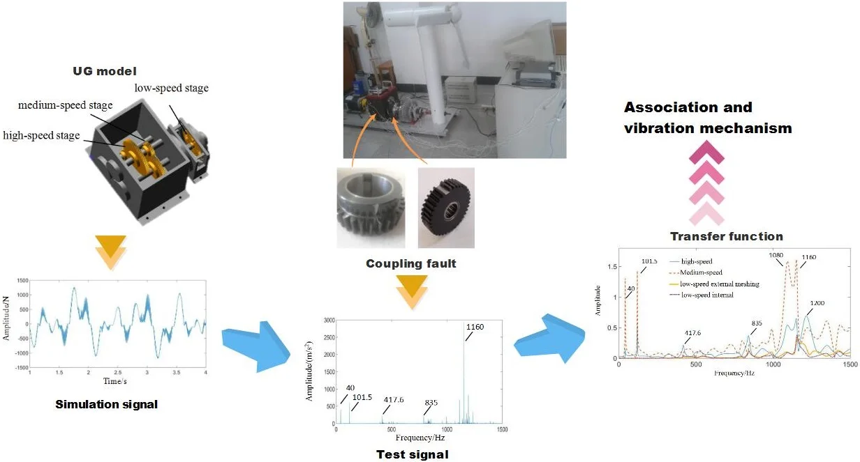
The test signal of multistage gear transmission system is complex. When coupling faults occur in the system, it is often difficult to accurately extract all kinds of fault features. In the past studies, we found that the fault signals have modulation and coupling effects. The failure of a gear is often reflected in the power spectrum in the form of associated changes in the meshing frequency of other stages. The separation of these features will facilitate the analysis of the coupling effects of multiple faults. The transfer characteristic method provides an effective method for decomposing such signal features. In this paper, through the analysis of transfer characteristics, the coupling fault transfer characteristics and the associated influence relationship of fixed-axis gear crack and planetary gear missing tooth are revealed. The contact force signals of each pair of gears with the coupling fault are obtained by dynamic simulation. The test signals of the fixed-axis gearbox and planetary gearbox are obtained under normal and coupling fault states. According to the method of system identification, the corresponding transfer function model of each path is established. The transfer process is revealed by the analysis of transfer characteristics. The association between two kinds of faults is found, which does not exist in a single fault and is difficult to obtain by signal analysis. This study reveals the association and vibration mechanism of the coupled fault, which provides a theoretical basis for fault diagnosis of multistage gears.
Highlights
- The contact force fault signals of each pair of gears are calculated by dynamic simulation. The test signals of the gearbox under normal and coupled fault conditions are obtained.
- Each path transfer function model is analyzed to reveal the transfer process.
- The study reveals the vibration mechanism and transfer characteristics of the coupling fault, as well as the associated influence relationship between crack and missing tooth.
1. Introduction
The test signal of multistage gear transmission system is complex. When coupling faults occur in the system, it is often difficult to accurately extract all kinds of fault features. There are also mutual modulation and coupling among the fault signals. What changes in the system are eventually caused by coupled signal. What kind of influence will be exerted on their fault features? These are issues of great concern to scientists and engineers.
In terms of the coupling characteristics of multistage gears, some scholars used the coupled dynamics model to analyze the coupling characteristics [1]. Others analyzed the dynamic coupling between time-varying mesh stiffness (TVM) and gears [2], the effects of the coupling strength [3], or the nonlinear dynamics of clearance variation and fault coupling [4]. The finite element model [5] was also used to study the coupled nonlinear dynamic characteristics of multistage gear transmission systems. The vibration signal model [6] was used to analyze the spectral characteristics of synchronous and asynchronous meshing. However, the final coupling effect of the actual signal may be slightly different from the theoretical result.
In the past decade, due to the development of big data, neural networks, machine learning and other disciplines, many new analysis algorithms for complex signals have appeared, such as the improved ant colony optimization algorithm (ICMPACO) proposed by Wu Deng [7], the new fault diagnosis (PABSFD) method based on the principal component analysis (PCA) and the broad learning system (BLS) [8], the new performance degradation prediction(HMEPEM) method based on High-Order Differential Mathematical Morphology Gradient Spectrum Entropy (HOMMSE), phase space reconstruction and Extreme Learning Machine (ELM) [9], the genetic and ant colony adaptive cooperation Optimization (MGACACO) algorithm [10], and so on [11, 12]. However, the complex structure and mechanism of mechanical equipment, coupled with the interference of its complex environment and the changes in working conditions brought by its complex tasks, make it difficult to analyze, process and diagnose the big data of mechanical equipment. Nowadays, the traditional academic thinking, which mainly focuses on observing phenomena, accumulating knowledge, designing algorithms, extracting features and analyzing decisions, is changing to a new academic thinking which takes mechanism as the foundation, data as the center, computing as the means and intelligent data analysis and decision-making as the demand. Therefore, with the rapid development of big data and algorithms, the research on mechanism cannot be ignored.
In a multi-stage gear transmission system, various fault characteristics are coupled together via path transfer. The difficulty of signal analysis lies in the fact that it is difficult to collect data at the ideal meshing point in the experimental test. Usually, the collected signals are the integrated signals on the surface of the gearbox body transmitted through multiple paths. To separate these signals, the transfer path analysis (TPA) method is a good method, which can decompose each path of the integrated signal. The coupling characteristics of multiple faults can be separated by splitting the contribution and characteristics of each component to the integrated signal. Transfer path analysis has been widely used in such fields as vehicles, high-speed trains and ships [14]. The application in gear transmission system is still in its initial stage. The current research focus is mainly on the planetary gearbox. Liu [15] proposed a comprehensive vibration signal model for a planetary gear set considering all the vibration sources and transfer path effects. Lei [16] constructed a vibration simulation model of the planetary gearbox by analyzing the transfer paths of each meshing vibration. Huang [17] used finite element model and MATLAB curve fitting toolbox to establish a mathematical model of the transfer path change law of planetary gearbox. Xu [18, 19] studied the influence of measuring points on transfer path under the conditions of planet gear crack and missing tooth fault. Chen [20] studied the propagation path and failure behavior of cracked gears at different initial angles. Transfer path analysis has not been applied in the study of the coupling fault vibration mechanism of multi-stage gear transmission systems.
For a multistage gear transmission system including both fixed-axis gears and a planetary gear train, multistage gear meshing and multiple transfer paths will interact with each other. When a fault occurs in one stage of meshing, it will appear in the form of other meshing frequencies in the power spectrum [21, 22]. Therefore, the fault characteristics and the fault transfer characteristics of a multistage gear transmission system should be studied specifically.
In this paper, the multistage gear transmission system is taken as the research object. The simulation and experimental methods are used to calculate the amplitude-frequency response curves of the transfer function,which transmit various meshing excitation forces to the planetary gearbox and fixed-axis gearbox under normal condition and coupling faults condition. The association between two faults was found out. The source and contribution of each frequency component in the test signal is studied. The fault characteristics and associated characteristics of coupling fault are summarized. This study provides a theoretical basis for the extraction and identification of coupling fault of multistage gear transmission system.
2. Dynamic model of multistage gear transmission system
2.1. Fault simulation test rig of a multistage gear transmission system
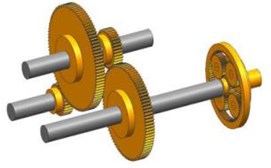
The multistage gear transmission system fault simulation test rig is taken as the research object, shown in Fig. 1. The vibration characteristic analysis and the transfer characteristic analysis are carried out.
Fig. 1Fault simulation test rig of a multistage gear transmission system: 1 – motor, 2 – torque sensor and encoder, 3 – two stage fixed-axis gearbox, 4 – radial load of bearing, 5 – one stage planetary gearbox, 6 – brake
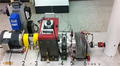
As can be seen from Fig. 1, there are two gearboxes in the gear transmission system test rig. The fixed-axis gearbox consists of two-stage fixed-axis gears, and the planetary gearbox consists of one-stage planetary gear train. The system structure diagram is shown in Fig. 2, where, is the input torque, driven by three-phase AC asynchronous motor. is the output torque, which can be set through the electromagnetic powder brake. Gears 1 and 2 form the high-speed gear pair. Gear 1 is the high-speed driving gear. Gear 2 is the high-speed driven gear. Gears 3 and 4 are the medium-speed driving gear and driven gear respectively. The planetary gear train is the low-speed stage, is the planetary gear, is the sun gear, is the planet carrier, and is the ring gear (fixed). The gears in the test rig are all spur gears with pressure angle of 20°. Gear parameters are shown in Table 1.
Fig. 2Structural diagram of the gear transmission system test rig
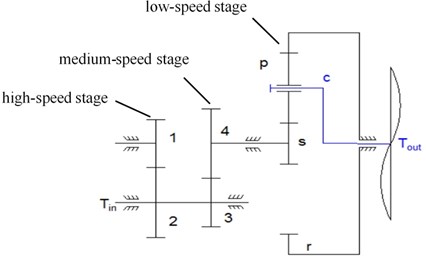
Table 1Gear parameters
Gear | Number of tooth | Mass /g | Rotational inertia / (g∙m2) | Face width / mm | Module / mm |
1 | 29 | 125 | 0.05 | 15 | 1.5 |
2 | 100 | 1224.5 | 6 | 15 | 1.5 |
3 | 36 | 224 | 0.14 | 15 | 1.5 |
4 | 90 | 1111 | 4 | 15 | 1.5 |
28 | 41 | 0.007 | 10 | 1.0 | |
36 | 34.6 | 0.01 | 10 | 1.0 | |
848.7 | 0.76 | 10 | 1.0 | ||
100 | 10 | 1.0 |
2.2. Dynamic model of gearboxes
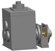
A fault simulation test rig of the multistage gear transmission system is taken as the research object. The corresponding 3D solid model was established and imported into ADAMS for dynamic simulation. Considering nonlinear characteristics of the gearboxes, the fixed axis gearbox and the planetary gearbox were softened [23, 24] to obtain more realistic gear dynamics characteristics. The gear, axis, box and other components were built. Gearboxes were integrally assembled by constraint relations. The assembled body and its internal structure are shown in Fig. 3.
Fig. 3The test rig solid model: a) assembled body, and b) internal structure
a)
b)
3. Analysis of dynamic excitation signals of gear meshing
The gear contact force can fully reflect dynamic response characteristics of the gear meshing process, and contribute to the qualitative analysis of system dynamic characteristics and fault characteristics under fault state. The contact force signals of the ADAMS dynamic model (Fig. 3) are solved under normal state and coupling fault state. The motor rotation frequency is 40 Hz (40 Hz). The motor drive torque is about 6 N·m (6 N·m). A load torque of 236 N·m ( 236 N·m) is applied to the planet carrier. Number of gear teeth are 29, 100, 36, 90, 28, 36, 100. Characteristic frequency parameters of gears at all stages in the test rig are shown in Table 2.
Table 2Main frequency parameters
Characteristic frequency | Computational formula | Value |
High-speed meshing frequency | 1160 Hz | |
Medium-speed meshing frequency | 417.6 Hz | |
Sun gear rotation frequency | 4.64 Hz | |
Planet carrier rotation frequency | 1.015 Hz | |
Low-speed (planetary) meshing frequency | 101.5 Hz | |
High-speed gear failure characteristic frequency | 40 Hz | |
Planetary failure characteristic frequency | 2.819 Hz |
3.1. Analysis of gear contact force signals under normal state
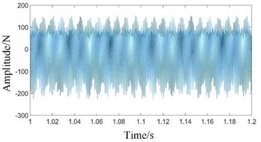
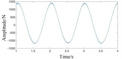
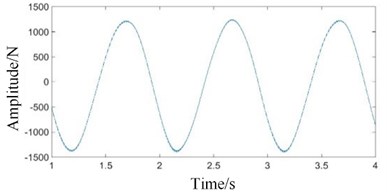
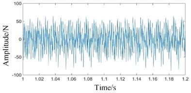
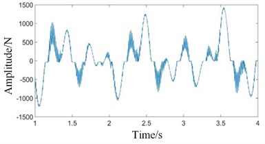
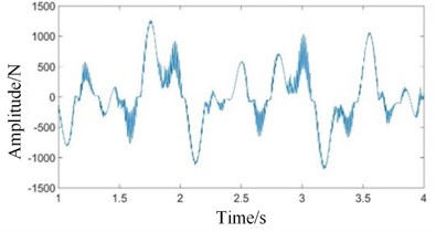
The dynamic simulation of the system under normal state is carried out. The contact force simulation signals of high-speed, medium-speed and low-speed external meshing (planetary gear meshing with sun gear) and low-speed internal meshing (planetary gear meshing with ring gear) are extracted respectively, as shown in Fig. 4.
As can be seen from Figs. 4(a) and 4(b), the waveforms of high-speed and medium-speed signals are relatively dense, mainly composed of high frequency component. In Figs. 4(c) and 4(d), the amplitude of low-speed contact force signal is large.
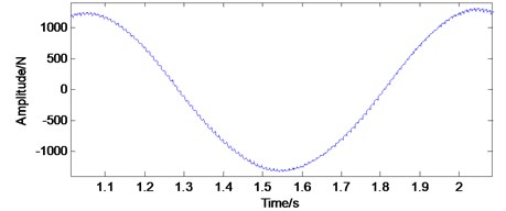
The ring gear in a planetary gearbox is generally stationary. When testing vibration signals, the sensor is usually mounted on the ring gear or the box connected to it. In operation, the positions of the two pairs of meshing points (the sun gear and the planet gear, the planet gear and the ring gear) relative to the sensor change with the rotation of the planet carrier. It is assumed that the sensor is mounted on the top of the ring gear. At the initial moment, one planetary gear is located on the top of the ring gear and directly below the sensor. As the planet carrier rotates, this planetary gear will gradually move away from the sensor. The meshing vibration of the planetary gear with the sun gear and the ring gear measured by the sensor will gradually decrease. When the planetary gear reaches the bottom of the ring gear, the amplitude of the meshing vibration signals reaches the minimum. As the planet carrier continues to rotate, the planetary gear will gradually approach the sensor. The sensor tests that the meshing vibration of the planetary gear with the sun gear and ring gear will gradually increase. When the planetary gear reaches the top of the ring gear, the amplitude of the meshing vibration signals reaches its maximum. Therefore, the passing effect of the planetary gear will have an amplitude modulation effect on the meshing vibration signals [25]. This amplitude modulation effect can be expressed by the Hanning function [26, 27]. If the planetary gearbox has planetary gears. Then, for each revolution of the planet carrier, planetary gears will pass directly under the sensor. The vibration signal is modulated times. The planet carrier rotation frequency (1.015 Hz) in Figs. 4(c) and 4(d) is the modulation frequency. The small fluctuation in Fig. 4(e) is the low-speed meshing frequency (101.5 Hz).
Fig. 4Time domains of gear contact force simulation signal under normal state: a) high-speed, b) medium-speed, c) low-speed external meshing, d) low-speed internal meshing, and e) low-speed external meshing magnification
a)
b)
c)
d)
e)
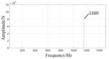
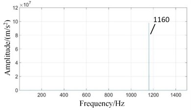
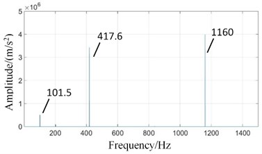
In order to observe the frequency components and the proportion of signals, the power spectrum corresponding to each time domain signal is obtained, as shown in Fig. 5.
In Fig. 5(a), the vibration frequency is dominated by high-speed meshing frequency (1160 Hz). Medium-speed meshing frequency (417.6 Hz) and low-speed meshing frequency (101.5 Hz) are relatively weak and hardly visible.
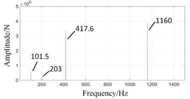
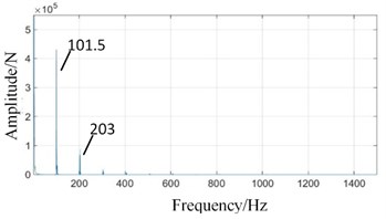
In Fig. 5(b), in addition to medium-speed meshing frequency (417.6 Hz), there are also high-speed meshing frequency (1160 Hz), low-speed meshing frequency (101.5 Hz) and its twice (203 Hz). It shows the correlation between various gear signals.
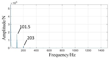
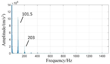
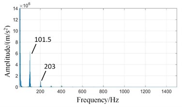
In Figs. 5(c) and (d), high-speed meshing frequency (1160 Hz) and medium-speed meshing frequency (417.6 Hz) attenuate obviously. The planet carrier rotation frequency (1.015 Hz) has the highest amplitude. The low-speed meshing frequency (101.5 Hz) and its higher order harmonics (, ...) are the main components. The response frequency amplitude of low-speed external meshing in Fig. 5(c) is larger than that of low-speed internal meshing in Fig. 5(d).
The above time domain and frequency domain charts conform to the basic law of the gear vibration, and verify the correctness of the model.
Fig. 5Frequency domains of gear contact force simulation signals under normal state: a) high-speed, b) medium-speed, c) low-speed external meshing, and d) low-speed internal meshing
a)
b)
c)
d)
3.2. Analysis of gear contact force signals under the coupling fault state
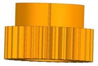
The high speed driving gear (gear 1) is set to have crack in the root. The depth of the crack is consistent with the crack gear in the test rig, as shown in Fig. 6. Crack tooth model is shown in author’s paper [28]. In this paper, crack length is 1 mm and crack angle is 70°. The planetary gear 1 in the low speed stage is set to have a missing tooth fault, as shown in Fig. 7.
Fig. 6Cracked gear: a) actual gear, and b) simulation gear model

a)
b)
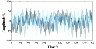
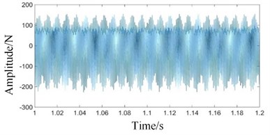
When the multistage gear transmission system has both fixed-axis gear crack fault and planetary gear missing tooth fault, the fault characteristics are coupled to each other to make the signal more complicated. The vibration signals of the meshing contact force of each gear are shown in Fig. 8.
Fig. 7The missing tooth planetary gear: a) actual gear, and b) simulation gear model

a)

b)
Fig. 8Time domains of meshing contact force simulation signals under coupling fault state: a) high-speed, b) medium-speed, c) low-speed external meshing, and d) low-speed internal meshing
a)
b)
c)
d)
Comparing Figs. 4(a) and 4(b) with Figs. 8(a) and 8(b), it can be seen that the meshing contact force signals of the high and medium speed stages have not changed significantly. Comparing Figs. 4(c) and 4(d) with Figs. 8(c) and 8(d), it can be seen that the time domain vibration signals of the low speed internal and external meshing contact forces under the coupling fault are obviously changed. The periodic pulse components of the signal increase, and the degree of signal distortion increases.
The signal characteristics of coupling fault are observed in frequency domain, as shown in Fig. 9.
As shown in Figs. 9(a) and 9(b), there is no obvious change in signal characteristics in the meshing contact force signals of the high and medium speed stages under coupling fault. In Figs. 9(c) and 9(d), the amplitudes of low-speed meshing frequency (101.5 Hz) and its doubled frequency increase obviously, and there are side-bands spaced apart by (0, 1, 2, ...; 1, 2, ...). The amplitudes of low-speed meshing frequency (101.5 Hz) in the low-speed meshing contact signals are compared and analyzed under the fixed-axis gear crack state, the planetary gear missing tooth state and the coupling fault state. It is found that the high-speed gear crack has little effect on the low-speed vibration response when only the fixed-axis gear is cracked. The main characteristic is the increase of the amplitude of its rotation frequency and the meshing frequency of medium-speed gear. When only the planetary gear tooth is missing, the high and medium speed vibration responses are not affected much. The amplitude of low-speed meshing frequency and its double increase. The amplitude of low-speed meshing frequency (101.5 Hz) increases sharply under the condition of the coupling fault, which indicates that the fixed-axis gear crack fault has an exciting effect on the planet gear tooth missing fault.
Fig. 9Frequency domains of meshing contact force simulation signals under coupling fault state: a) high-speed, b) medium-speed, c) low-speed external meshing, and d) low-speed internal meshing
a)
b)
c)
d)
4. Test signal analysis and transfer function calculation of test rig
4.1. Test signal characteristics under normal state
The acceleration response signals on the surface of gearboxes under normal state were measured, in which the input axis frequency was 40 Hz, the output axis was loaded with 10 V. Considering the difference of collected signals on different boxes, the acceleration vibration response signals of fixed-axis gearbox and planetary gearbox in horizontal direction were measured separately. The test results of two boxes on the surface under normal state are shown in Fig. 10.
Fig. 10Power spectrum signals of the test rig under normal state: a) fixed axis gearbox, and b) planetary gearbox
a)
b)
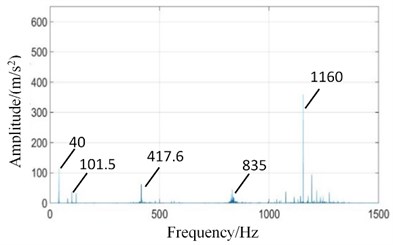
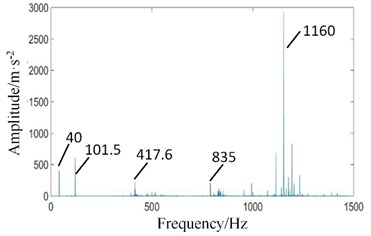
It can be seen from Fig. 10 that the main frequency components of two boxes in normal state are high-speed meshing frequency (1160 Hz), high-speed axis frequency (40 Hz), medium-speed meshing frequency (417.6 Hz) and its doubled frequency 2 (835 Hz), low-speed meshing frequency (101.5 Hz), etc.
Affected by distance, the signal intensities of two boxes are different. In Fig. 10(b), input axis rotation frequency (40 Hz) and high-speed meshing frequency (1160 Hz) are significantly weakened because of far away from high-speed stage. The amplitude of low-speed meshing frequency (101.5 Hz) is enhanced.
4.2. Transfer function of each transfer path under normal state
Affected by factors such as time-varying meshing stiffness, transmission error, meshing impact, etc., under normal condition, the meshing of gear teeth will also generate dynamic meshing forces. Not only that, it also causes fault excitation forces under fault conditions. These excitation forces cause gear vibration. The vibration signals are constantly aliased in a certain way, and are transmitted to the outside of the box through different media and different paths such as transmission components, lubricants, and air. The transmission direction of the vibration signal in the transmission process is arbitrary. But in general, it will be transmitted to the gear box through gear-key-shaft-bearing-box. During the transmission of vibration signals inside the box, there are not only static transmission paths in the static structure, but also dynamic transmission paths formed by various transmission components. These transmission paths, like filters, affect the amplitude and phase of different frequencies in the signal transmission process.
Fig. 11The amplitude-frequency response curves of transfer function of each transfer path under normal state: a) contact forces are transmitted to fixed axis gearbox, and b) contact forces are transmitted to planetary gearbox
a)
b)
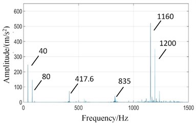
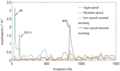
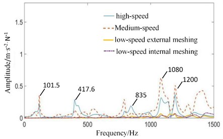
The vibration transfer path system model of multistage gear transmission system is established by system identification method. The four contact forces in Fig. 4 are taken as the input excitation forces, and the test signals on the surface of gearboxes in Fig. 8 are taken as the output. The model is solved using an automatic regression exogenous (ARX) model with multi-point input and single-point output, and the Tustin inverse transform method. The amplitude-frequency response curves of transfer function of meshing excitation forces transmitted to fixed-axis gearbox and planetary gearbox under normal state are shown in Fig. 11.
In Fig. 11(a), 40 Hz has the highest amplitude, and the frequency is high-speed axis frequency. Therefore, high-speed stage contact force has the greatest contribution to the frequency. Medium-speed and low-speed also have some contributions. Meshing frequencies of , and are not obvious. But meshing frequency of 2 (835 Hz) is obvious, which comes from the contribution of low-speed internal and external meshing process [29].
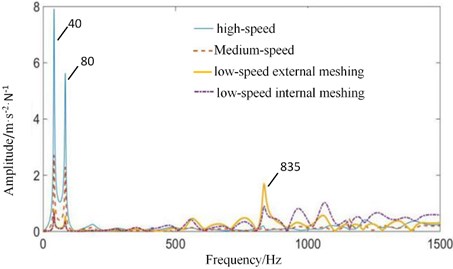
In Fig. 11(b), planetary gearbox is far away from high-speed stage. Signal intensity of high-speed stage is weakened, and low-speed signal is enhanced. The amplitude of high-speed axis rotation frequency (40 Hz) decreases. The frequency characteristic of low-speed meshing frequency (101.5 Hz) increases. Low-speed internal and external meshing also causes a large frequency component of 2 (835 Hz).
4.3. Test signal characteristics of coupling fault
The normal high-speed driving gear was replaced by the gear with root crack fault, and the normal planetary gear was replaced by the missing tooth one. The test signals of the two gearboxes are shown in Fig. 12.
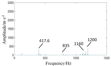
In Fig. 12(a), The high-speed shaft frequency (40 Hz) peak disappears in the fixed-axis gearbox spectrum, while the side band (1, 2, ...) appears around the meshing frequency of the high-speed stage. The amplitudes of medium-speed meshing frequency and 2 increase slightly. However, the amplitude of the high-speed meshing frequency decreases instead.
The amplitude of planetary gear meshing frequency (101.5 Hz) affected by the missing tooth fault of planetary gear is increased in the spectrum of planetary gearbox in Fig. 12(b), which is consistent with the basic law of gear fault. The amplitudes of the medium-speed meshing frequency and its doubled frequency 2 are also slightly increased due to the influence of the fixed-axis gearbox. The amplitude of high-speed meshing frequency increases sharply.
Fig. 12Power spectrum signals of test rig under coupling fault state: a) fixed axis gearbox, and b) planetary gearbox
a)
b)
4.4. Transfer function of each transfer path under the state of the coupling fault
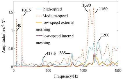
The four contact force simulation signals under the coupling fault state in Fig. 9 are taken as input excitation forces. The coupling fault signals tested on the gearbox surface in Fig. 12 are taken as the output. The amplitude-frequency response curves of transfer function of meshing excitation forces transmitted to fixed-axis gearbox and planetary gearbox under the coupling fault state are shown in Fig. 13.
As can be seen from Fig. 13, the main contribution of the increase in the amplitude of the planetary gear meshing frequency (101.5 Hz) is not from its own vibration, but from the high-speed stage and the medium-speed stage, which is consistent with the conclusion in 3.2 in that the fixed-axis gear crack fault has an exciting effect on the planetary gear tooth missing fault. Comparing Fig. 13 and Fig. 11, it can be seen that the contribution of each gear to the high-speed stage meshing frequency (1160 Hz) is obviously increased under the influence of fixed axis crack fault. It is worth noting that the contributions of the low-speed internal and external meshing in the planetary gearbox to far exceed the contribution to itself. The medium-speed stage is connected to the high-speed stage and the low-speed stage at the same time. Both kinds of faults have an impact on it. So that the contribution of the medium-speed stage in the full frequency band is improved.
It can be seen from the contribution of each meshing frequency that there is an interaction relationship between the gears of each stage. The main contribution of low-speed fault characteristics comes from the high-speed and medium-speed stage, while the features of the high-speed stage include the contribution of the low-speed stage. Both of them affect the medium-speed stage, which makes the medium-speed stage contribute a lot in the full frequency band. This interrelated relationship does not exist in the case of a single fault.
Fig. 13The amplitude-frequency response curves of transfer function of each transfer path under the coupling fault state: a) contact forces are transmitted to the fixed axis gearbox, and b) contact forces are transmitted to the planetary gearbox
a)
b)
5. Conclusions
In this study, the fault simulation test rig of the multistage gear transmission system is taken as the research object. The three-dimensional solid rigid-flexible coupling model of system is established. According to the method of system identification, the transfer function models corresponding to each path are established. The signal transfer process is revealed through the transfer characteristic analysis. The associated fault characteristics and fault transfer characteristics between gears under the coupling fault state are obtained. It is found that most of the energy contribution of the planetary gear fault features comes from the fixed axis gear, while some of the energy contribution of the fixed axis fault features come from the planetary gear. There is a interrelated relationship between the two faults, which does not exist in the case of a single fault. This relationship can be explored by the transfer function method, which cannot be obtained by the signal analysis method. The vibration transfer mechanism of the coupling fault in the multistage gear transmission system studied in this paper provides a theoretical basis for fault diagnosis of multistage gear systems.
References
-
Wei J., Zhang A. Q., Qin D. T., Shu R. Z. Coupling vibration analysis for planetary gear system considering flexible structure. Journal of Mechanical Engineering, Vol. 53, Issue 1, 2017, p. 1-12.
-
Wang Q. B., Li Z. W., Ma H., Wen B. Effects of different coupling models of a helical gear system on vibration characteristics. Journal of Mechanical Science and Technology, Vol. 31, Issue 5, 2017, p. 2143-2154.
-
González-Cruz C. A., Jáuregui-Correa J. C., Domínguez-González A., et al. Effect of the coupling strength on the nonlinear synchronization of a single-stage gear transmission. Nonlinear Dynamics, Vol. 85, 2016, p. 123-140.
-
Wang X. Stability research of multistage gear transmission system with crack fault. Journal of Sound and Vibration, Vol. 434, 2018, p. 63-77.
-
Zhu C. C., Huang Z. H., Tang Q., Tan Y. H. Analysis of nonlinear coupling dynamic characteristics of gearbox system about wind-driven generator. Journal of Mechanical Engineering, Vol. 41, Issue 8, 2005, p. 203-207.
-
Cristián M. V. Vibration characteristics of single-stage planetary gear transmissions. Revista Chilena De Ingeniería, Vol. 22, Issue 1, 2014, p. 88-98.
-
Deng W., Xu J. J., Zhao H. M. An improved ant colony optimization algorithm based on hybrid strategies for scheduling problem. IEEE Access, Vol. 7, 2019, p. 20281-20292.
-
Zhao H. M., Zheng J. J., Xu J. J., Deng W. Fault diagnosis method based on principal component analysis and broad learning system. IEEE Access, Vol. 7, 2019, p. 99263-99272.
-
Zhao H. M., Liu H. D., Xu J. J., Deng W. Performance prediction using high-order differential mathematical morphology gradient spectrum entropy and extreme learning machine. IEEE Transactions on Instrumentation and Measurement, 2019, https://doi.org/10.1109/TIM.2019.2948414.
-
Deng W., Zhao H. M., Zou L., Li G. Y., Yang X. H., Wu D. Q. A novel collaborative optimization algorithm in solving complex optimization problems. Soft Computing, Vol. 21, Issue 15, 2017, p. 4387-4398.
-
Deng W., Zhao H. M., Yang X. H., Xiong J. X., Sun M., Li B. Study on an improved adaptive PSO algorithm for solving multi-objective gate assignment. Applied Soft Computing, Vol. 59, 2017, p. 288-302.
-
Liu Y. Q., Wang X. X., Zhai Z. G., Chen R., Zhang B., Jiang Y. Timely daily activity recognition from headmost sensor events. ISA Transactions, Vol. 94, 2019, p. 379-390.
-
Li Z. X., Yan X. P., Yuan C. Q., Zhao J. B., Peng Z. X. A fault diagnosis approach for gears using multidimensional features and intelligent classifier. Noise and Vibration Worldwide, Vol. 41, Issue 10, 2010, p. 76-86.
-
Magrans F. X., Poblet-Puig J., Rodríguez-Ferran A. The solution of linear mechanical systems in terms of path superposition. Mechanical Systems and Signal Processing, Vol. 85, Issue 1, 2017, p. 111-125.
-
Liu L. B., Liang X. H., Zuo M. J. Vibration signal modeling of a planetary gear set with transmission path effect analysis. Measurement, Vol. 85, 2016, p. 20-31.
-
Lei Y. G., Tang W., Kong D. T., Lin J. Vibration signal simulation and fault diagnosis of planetary gearboxes based on transmission mechanism analysis. Journal of Mechanical Engineering, Vol. 50, Issue 1, 2014, p. 61-68.
-
Huang Y. H., He G. L., Zeng Z. J. Transfer path analysis of meshing vibration signal of planetary gear sets. Journal of Chongqing University of Technology (Natural Science), Vol. 29, Issue 6, 2015, p. 37-40.
-
Xu Y. X., Zhao X. F., Xiong Y. Q. Gear crack fault identification for multi-stage gearbox based on signal propagation path. Chinese Journal of Scientific Instrument, Vol. 37, Issue 5, 2016, p. 1018-1024.
-
Xiong Y. Q., Xu Y. X. Identification of planetary gear tooth missing fault based on signal propagation model. Chinese Journal of Scientific Instrument, Vol. 37, Issue 2, 2016, p. 249-255.
-
Chen Y. X., Jin Y., Liang X. H., Kang R. Propagation path and failure behavior analysis of cracked gears under different initial angles. Mechanical Systems and Signal Processing, Vol. 110, 2018, p. 90-109.
-
Pattabiraman T. R., Srinivasan K., Malarmohan K. Assessment of sideband energy ratio technique in detection of wind turbine gear defects. Case Studies in Mechanical Systems and Signal Processing, Vol. 2, 2015, p. 1-11.
-
Cooley C. G., Parker R. G. The geometry and frequency content of planetary gear single-mode vibration. Mechanical Systems and Signal Processing, Vol. 40, Issue 1, 2013, p. 91-104.
-
X Ma. G., Yang W., You X. M., Chen C. G., ZhangF. Multi-body dynamical analysis on rigid-flexible coupling for planetary gear system. Chinese Journal of Construction Machinery, Vol. 7, Issue 2, 2009, p. 146-152.
-
He Y. L., Huang W., Li C. W., Du J., Hou H. C. Flexible multibody dynamics modeling and simulation analysis of large-scale wind turbine drivetrain. Journal of Mechanical Engineering, Vol. 50, Issue 1, 2014, p. 61-69.
-
Feng Z. P., Zhu F. L. Vibration spectral characteristics of distributed gear fault of planetary gearboxes. Proceedings of the CSEE, Vol. 33, Issue 2, 2013, p. 118-125+21.
-
Inalpolat M, Kahraman A. A theoretical and experimental investigation of modulation sidebands of planetary gear sets. Journal of Sound and Vibration, Vol. 323, Issues 3-5, 2009, p. 677-696.
-
Inalpolat M, Kahraman A. A dynamic model to predict modulation sidebands of a planetary gear set having manufacturing errors. Journal of Sound and Vibration, Vol. 329, Issue 4, 2010, p. 371-393.
-
Wang X. Study on failure characteristics of gear transmission system with crack fault. UPB Scientific Bulletin, Series D: Mechanical Engineering, Vol. 80, Issue 2, 2018, p. 141-152.
-
Yang Y., Chu Z. G., Xiong M. Transfer path analysis of booming noise in a car cabin based on impedance matrix method. Journal of Vibration and Shock, Vol. 33, Issue 18, 2014, p. 164-169+176.
About this article

This research is supported by Natural Science Basic Research Program of Shaanxi (Program No. 2019JQ-898), China.
