Abstract
This paper explores the model for the analysis of two misaligned Jeffcott rotors flexibly-coupled through a Hooke’s joint. The aim is to present a transmission on non-linear shafts-coupling model subjected to elastic deformation. The model provides some insight into the transmission motion on misaligned rotor-system under the influences of unbalance and helps to understand the dynamic characteristics of the coupling twin-rotor system. Modelled results reveal that the unbalance and Hooke’s joint in the drive and driven shafts lead to alternating stress fields in the rotating shafts.
Highlights
- Numerical analysis of the unbalanced twin-rotor Interconnect through Hooke‘s joint, including lateral and torsional deformation
- Expression of a small perturbation parameter depending on the driver shaft speed is established
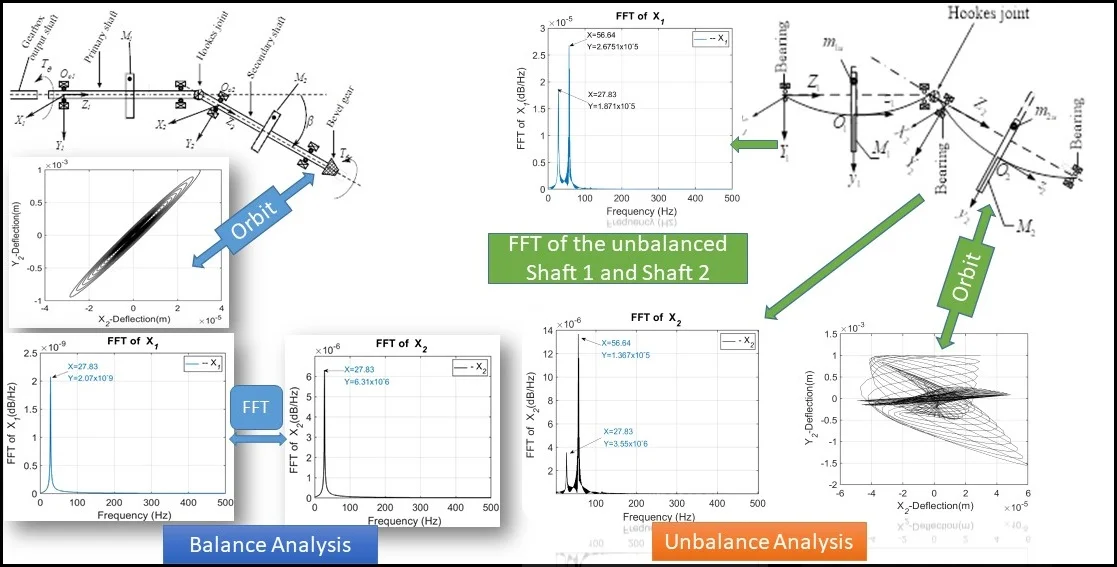
- FFT exhibited a higher frequency amplitude of the balanced system on both shaft 1 and shaft 2.
- FFT as well reflected the synchronous excitation frequencies due to the unbalance effect.
- The trajectory of the balanced shaft centre 1 and 2 in steady-state is orbital stable.
- Irregularity in orbit orientation is perceptible for unbalanced shafts near the first critical speed.
1. Introduction
The study of vibratory behaviour of connected shafts covers several branches of mechanics and mathematics. The Cardan joint is amongst the most commonly used universal joints in the mechanical couplings when the input drive and output driven shaft are not aligned [1]. Two shafts are considered to be misaligned when the rotational axes of primary and driven shafts are non-coincident at the point of coupling. Usually, a real shafts misalignment into a rotor system is subjected to the influence of the angular joint angle, as shown in Fig. l(a).
The study of the dynamics of Cardan shafts connected by a universal joint and affected by a mass unbalance is a delicate problem that covers different technical and mathematical aspects. The analysis of such a system requires appropriate modeling for both the unbalance and the connected shafts. It is a complex non-linear system requiring a relevant description. A fine modelling of the rotating shafts as well as transmission elements allowing the identification of the parameters characterizing the transmission of motion from one shaft to another. The shafts of the rotating machines constitute structures that are rather complex to analyse. Depending on the applications for which they are intended, they are often composed of several sections and subject to solicitations of various origins. The major faults related to the joints transmission devices are mainly abnormal noise, high vibrations, and sometimes torsional deformations. The probability of a fault in the universal joint, causing errors in the engine and transmission is higher than in other parts of a vehicle [2]. The study of the influence of both unique and combined faults in the structure connected by a universal joint is therefore important. A substantial number of studies have been conducted on a structure connected by universal joints using a simulation method. However, the quantitative relation between unique or combined faults on the performance of the transmission of motion has still not been adequately investigated.
In this paper, the transmission performance with regard to the unbalance faults associated with the self-aligned Hooke’s joint, including lateral and torsional deformation, is analysed. First, a transmission model is proposed, and a new model for unbalanced faults associated with shaft motions is presented. Then, the transmission performance analysis is discussed based on a perturbation of small order of the parametric excitation due to Hooke’s joint.
2. Modelling approach and assumptions
The main objective of the work is to derive a basic mathematical model of coupled twin-rotor which can be used to study the vibration response of unbalanced rotor systems. The model is based on a simple Jeffcott’s approach aiming at an intuitive and simple interpretation of the system excitation-response relationships. Fig. 1(a) represents the modelled twin-rotor system. Its basic elements are the primary and secondary shafts, bearings, and a Hooke’s coupling. The system considered comprises two symmetric elastic shafts each carrying a massive rigid disk; which are characterized by the system’s kinetic energy. The two discs are of masses and and carry eccentric unbalanced lumps of masses, and respectively. The following assumptions and considerations have been made: 1. The two shafts are flexible to assure lateral and torsional vibration. 2. Gyroscopic effects due to discs’ spinning are neglected. 3. The shafts flexural stiffness are considered to be relatively small compared to the bearings’ stiffness. 4. The linear viscous damping effects of the bearings has been considered. 5. Gyroscopic effects due to the spinning disks are negligible. 6. Self-aligning bearings are assumed, to ensure that the bearing takes up the bending mode shape of the shafts at the supports. 7. The power spends to overcome the torsional vibration is nil. Therefore, the system’s d.o.f.s are lumped at the centres of the inertias and their net displacements are as follows: the motor mass moment of inertia that undergoes rigid-body rotation of the gearbox output inertia only. -Net mass moment of inertia of the mass-disc transmitted through the Hooke’s joint that undergoes rigid-body rotation , and the angle of intersection of the primary and secondary shaft axes . Hooke’s couplings have been modelled by applying the kinematics associated with universal-joints [3].
Fig. 1a) Kinematic sketch of the Cardan shaft system, b) A dynamic model of Cardan shaft system
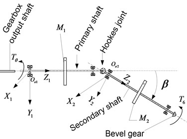
a)
b)
It is well known that in automotive assembly, the difference between input and output motions of a Cardan shaft is kept low to reduce vibration in the coupling [3]. This is achieved by curbing to a low value, usually below 6°. The kinematic relationship between the driver and the driven shaft can be expressed as [4]:
where is a small perturbation parameter that depends on expressed as [5]:
The difference between and the output for infinitesimal small-angle approximation gives:
2.1. Lagrangian formulation of the system
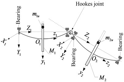
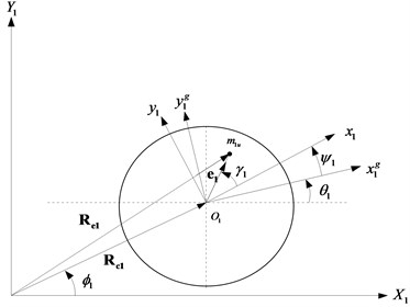
Combined two inertial reference frames, , , and , , as shown in Fig. 2 have been adopted for the global representation of the lumped mass system. , , is fixed to the gearbox with coincident with the gearbox output shaft axis. Whereas, , , is attached to the left bearing of the secondary shaft such that, is coincident with the central axis of the bearing as indicated in Fig. 1(a). The vectors and represent the global position of and respectively. The pairs of vectors , and , respectively, represent the centres of the rotor masses and . The kinetic energy of the parts of the driveline coupled with the Cardan shaft is expressed as:
Differentiating Eq. (4), assigning and performing appropriate substitutions leads to the kinetic energy Eq. (5) below:
Fig. 2a) Deformed configuration of shaft1 carrying disc 1, b) deformed shaft 2 carrying disc 2
a)

b)
2.2. System potential energy
The system potential energy comprises the shaft lateral vibration strain energy and the torsional strain energy expressed as:
where, , , , , are the shaft stiffness, and are the torsional stiffness coefficients associated with the system degrees of freedom.
2.3. The Rayleigh dissipation function
Taken into account the effect of damping coefficient, and neglecting the exciting external force and the external torque, the Rayleigh’s dissipation function can be expressed as:
where, , , , are the flexural vibration damping the respective degree of freedom’s damping coefficients, and are the torsional vibration damping of the first and second shaft respectively.
2.4. The equations of motion
Lagrangian equation of a system in each generalized coordinate frame is:
Upon substitution of Eqs. (5)-(7) into Eq. (8), performing requisite differentiation and manipulation, the system dynamic equation reads:
The elements of mass, stiffness and damping matrices in their final forms are:
The vectors , have been analytically obtained by the Lagrangian formalism and are the vector of Coriolis couple corresponding to the rotor quadratic velocity excited torque, and the elastic interaction of rotor’s stiffness of the secondary shaft in terms of the perturbation of primary shaft assembly through the Hooke‘s joint.
3. Results and analysis
The numerical solutions of Eq. (9) of the twin-propeller shafts are evaluated using the values of parameters prescribed in [6]. In the first simulation, the rotor system was operated with zero eccentric mass and was therefore considered balanced. Figures below show the variation of perturbation parameter on frequency and orbit of the primary and secondary unbalanced shafts.
To perform unbalance fault simulation, a mass of pre-determined weight was introduced and results through orbit and FFT are presented as shown in Figs. 7, 8 and 9.
Fig. 3Variation of the perturbation function
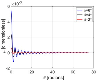
Fig. 4FFT of the primary shaft perturbation
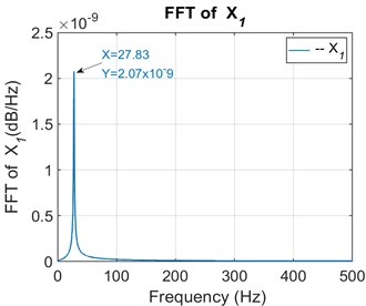
Fig. 5Orbit pattern of the balanced output shaft (stable operation)
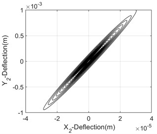
Fig. 6FFT of the secondary shaft
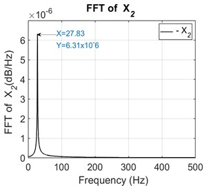
Fig. 7Orbit pattern of the unbalanced output shaft (unstable operation)
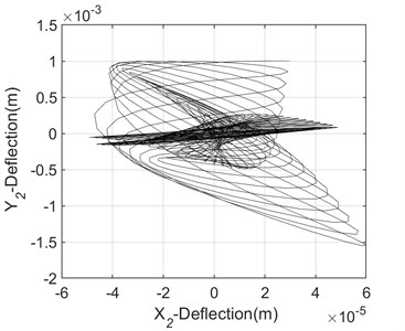
The analysis of obtained results shows that vibration due to combined misalignment and unbalance is characterised by 2 times running speed frequency component at high-level harmonics, and an increasing of the irregularity of the shaft orbit loops with a divergent static equilibrium trajectory (Fig. 7). FFT analysis in an interconnected twin-rotor through Hooke’s joint yielded satisfactory results when performing online unbalance fault identification. At present frequency domain features are effective for vibration analysis of unbalanced rotating machine by indicating more easily the first and second resonance frequency components. However, suitable vibration techniques need to be implemented as per the need to obtain an optimal output of non-stationary vibration signals.
Fig. 8FFT of the primary unbalanced shaft 1
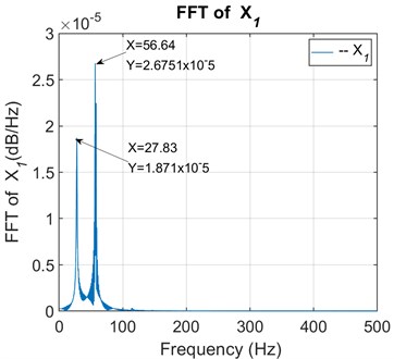
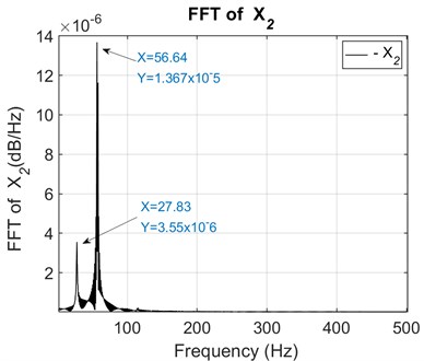
Fig. 9FFT of the secondary unbalanced shaft 2
4. Conclusions
The proposed model of interconnected twin-rotor through Hooke’s joint has been effective in extracting unbalancing feature faults using the orbit patterns and FFT spectrum of the Cardan shaft. In order to validate the correctness of the proposed interconnected twin-rotor model, it is very necessary to perform systematic experiments for vibration measurement and unbalance fault detection in rotating machinery in real rotating machinery.
References
-
Erdman G., Sandor G. N. Mechanism Design. Prentice Hall Publication, 1991.
-
Zhang S., Chen Y. Dynamics modeling of vehicle shimmy system with clearance in the universal joint movement. Automobile Application Technology, Vol. 4, 2012, p. 46-49.
-
Alugongo A. A. Parametric excitation and wavelet transform analysis of a ground vehicle propeller shaft. Journal of Vibration and Control, Vol. 20, Issue 2, 2012, p. 280-289.
-
Evernden H. I. F. The propeller shaft or Hooke’s coupling and the Cardan joint. Proceedings of the Institution of Mechanical Engineers: Automobile Division 2, Vol. 1, 1948, p. 100-110.
-
Alugongo A. A. Parametric vibration of a cardan shaft and sensitivity analysis. Proceedings of the World Congress on Engineering and Computer Science, 2018.
-
Tchomeni B. X., Alugongo A. Modelling and numerical simulation of vibrations induced by mixed faults of a rotor system immersed in an incompressible viscous fluid. Advances in Mechanical Engineering, 2018, https://doi.org/10.1177/1687814018819341.
About this article

The authors acknowledges the support of the Vaal University of Technology, South Africa.
