Abstract
Nowadays, two-stage mounting system having integral intermediate mass is widely applied and researched to attenuate vibration of marine machinery equipment, while two stage mounting system having distributed intermediate mass which has the feature of lightweight and installation dimension is rarely used and studied. The theoretical models of two types of mounting systems are set up and force transmissibility rate of the two mounting systems are deduced through four-pole parameters method. A scale experimental prototype is established to test the isolation efficiency of the two-stage mounting system having distributed intermediate mass. FEMs of the two systems are established to make a comparison ascertaining the difference between the two about vibration isolation efficiency at the different frequency. The result shows that two stage mounting system having distributed intermediate mass achieve better vibration isolation efficiency and take less space than two-stage mounting system having integral intermediate mass if with equivalent intermediate mass. Two-stage mounting system having distributed intermediate mass can meet the requirements of practical projects and provides a new way for engineer to refer to when meet with machinery equipment vibration problems.
1. Introduction
In many segments of industry the trend in the past few years has been towards more complex equipment and machines, which are lighter and more compact than their predecessors and which operate at greater speeds and power ratings. To the vibration engineer this trend has meant more problems associated with vibration isolation problems: i.e., more excitation available and more components likely to be affected adversely by them so that it has become increasingly important to provide vibration isolation systems that will retain their effectiveness [1, 2]. Machinery mounting system is one of the most significant vibration and noise attenuation technology of mechanical equipment [3-5].
It has been extensively believed that the intermediate mass of two-stage mounting system would be better to improve isolation efficiency than one-stage mounting system [6, 7]. At present, two-stage mounting system having frame structure intermediate mass like raft mounting system is widely used in the field of naval vessels which have been gaining widespread attention. In practical application, the intermediate mass usually takes amount of 20-30 % of the isolated mass [8], but in special cases where dimensions and weight are strictly limited, this way may not be suitable. Thus, the other Machinery mounting system that is two-stage mounting system having distributed intermediate mass which takes less space would play a more important role in the field of vibration noise controlling.
The simplified theoretical and finite element model of the two kinds of two-stage mounting systems are analysed in the paper. The equation of two kinds of mounting systems’ isolation effectiveness expressed by transmissibility were deduced through four-pole parameter method. A comparison between the two mounting systems to ascertain the difference about vibration isolation efficiency at different specific frequency through FEM model analysis was made. A scale experimental platform was established to test the isolation efficiency of the two-stage mounting system having distributed intermediate mass.
The research results based on the calculation and analysing on the two kinds of mounting systems can provide a reference for engineer when designing mounting system for machinery equipment.
2. Mounting system theoretical model
2.1. Basic theory of four-pole parameters method
The behaviour of mounting systems is complicated and extremely hard to predict because of wave effects. To depict the behaviour of system’ dynamic performance is difficult so that to simplify practical mounting system is necessary [9, 10].
Four–pole parameters method is an essentially simple idea and for this reason is helpful in providing a point of view [11]. All of the pertinent properties of a system can be expressed in terms of four pole parameters which characterize only the system for which they are determined; their value is not influenced by the preceding or subsequent mechanical systems.
A linear mechanical system is shown schematically in Fig. 1. The system may be comprised one or more lumped or distributed elements, or be constructed from any combination of such elements. The input side of the system vibrates sinusoidally with a velocity in response to an applied force . In turn, the output side of the system exerts a force on the input side of some further system, sharing with it a common velocity . Thus the system shown is said to have input and output terminal pairs, a force and velocity at the input terminal pair giving rise to a force and velocity at the output terminal pair, the reaction of any subsequent mechanical system being accounted for. Forces are considered positive when directed to the right [12, 13].
Fig. 1Schematic diagram of mounting system
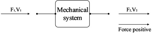
The vibration response of the four-terminal system of Fig. 1 can be represented by the following matrix equation. The term four-pole parameters are the name applied to the four coefficients in the pair of equation shown below:
It is directly apparent that:
where the subscript indicates that the output terminal pair is blocked and the subscript indicates the output terminal pair is free(unrestrained. The parameters and are dimensionless; has the dimensions of impedance and the dimensions of mobility. Normally impedance data is obtained by experiments in practical engineering application [14]. The four-pole parameter of basic mechanical components are as followed below.
Mass:
Spring:
Damping:
where , , represent mass, stiffness of spring and damping factor respectively. And , represents angular frequency.
2.2. Two-stage mounting system having integral intermediate mass
A two-stage mounting system having integral intermediate mass is shown diagrammatically in Fig. 2. Here a machine of mass vibrates with a sinusoidally varying velocity under the action of a force . The machine is isolated from a non-rigid of arbitrary impedance by two resilient mounts between which is located an arbitrary impedance . is the impedance of a lumped intermedia mass . represents the force transiting to foundation in Fig. 3.
To simplify the system, vertical vibration was studied only.
Fig. 2Simplified two-stage mounting system having integral intermediate mass model
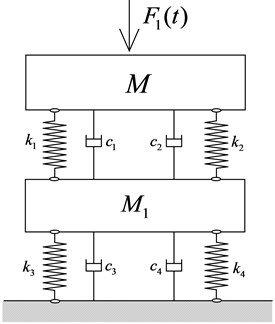
Fig. 3An equivalent four-terminal system with series-connected components
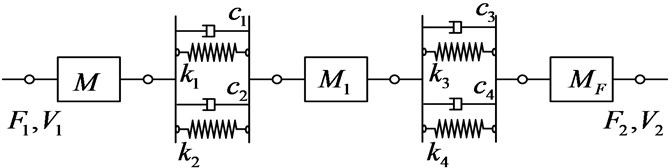
, , , , are impedance of upper isolator, lower isolator, intermediate mass, mechanical device and foundation respectively:
where , , represent equivalent mass, stiffness, damping factor of foundation respectively.
It’s possible to envisage the overall system as shown in Fig. 3 and the following relation between the input and output forces and velocity may be written down directly:
where , , , , , are the four-pole parameters of mounting system compounded by upper device, isolators, foundation and intermediate mass:
The receiver’s force when the mount is absent:
The most commonly used to measure performance of a mounting system in a given situation is the force transmissibility [15]. Transmissibility may be defined as the ratio of the force amplitude at the receiver to the force amplitude on the source side of the system. That is:
Inspection of Eqs. (5-8), the force transmissibility of mounting system can be easily obtained as shown below:
2.3. Two-stage mounting system having distributed intermediate mass
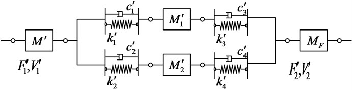
As is shown in Fig. 4 and Fig. 5, the intermediate mass is divided into several parts (two parts in simplified model). To simplify calculation, , , , .
For the two-stage mounting system as shown in Fig. 4. It follows directly that:
Fig. 4Simplified two-stage mounting system having distributed intermediate mass model
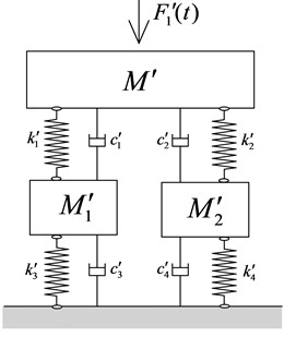
Fig. 5An equivalent four-terminal system with series-connected components
The four-pole parameters now become:
The receiver’s force when the mount is absent is:
Combining Eqs. (10-12) yields the isolation effectiveness of mounting system expressed by transmissibility can be easily obtained:
2.4. Numerical analysis
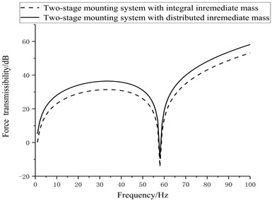
Numerical analysis is presented according to Eq. (9) and (13) derived based on a group of baseline parameters. Amounts of upper device is 1000 kg, the stiffness of upper isolators is 10e6 N/m, damping factor 0.1; the stiffness of lower isolators is 10e6 N/m, damping factor 0.001; the impedance of foundation equals 10e6 N·s/m. To compare the force transmissibility performance of two-stage mounting system with different forms of intermediate mass, the force transmissibility curves were obtained based on the group of baseline parameters under the condition that amounts of different forms of intermediate mass equals, that is 300 kg.
Fig. 6 shows the force transmissibility of two-stage mounting system with distributed and integral intermediate mass. It can be seen that two stage mounting system having distributed intermediate mass achieve better vibration isolation efficiency than two-stage mounting system having integral intermediate mass if with equivalent intermediate mass.
Fig. 6Comparison of force transmissibility curves
3. Experiment
To validate the theoretical analysis in this paper, a scale experimental prototype is established to test the vibration isolation efficiency of the two-stage mounting system having distributed intermediate mass. The experimental prototype is shown in Fig. 7.
Fig. 7A scale experimental prototype having distributed intermediate mass
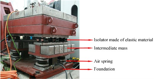
Isolators made of hard elastic material were used in the upper mount whose natural frequency were about 8 Hz and stiffness is 1.5×10e6 N/m, damping factor 0.09. Air spring was used in the lower mount whose natural frequency was about 4 Hz, stiffness is 10e6 N/m and damping factor 0.05. Intermediate mass amounts about 20 % of the total mass of the upper body including a vibration generator to simulate vibration source and rack to hold it. The vibration generator generates vibration at a precise frequency. The isolation effectiveness expressed by acceleration tested by PULSE exploited by Brüel&Kjær was shown in Table 1. All of the measurements summarized here were obtained after post-process using Pulse Reflex, driven by1/3 octave band filtered white noise, and by measuring 1/3 octave bands. Experimental results showed that satisfactory isolation effectiveness evaluated by vibration lever difference could be obtained by using distributed intermediate mass as frame structure intermediate mass does.
Table 1Measured isolation effectiveness of mounting system experimental prototype. (Reference acceleration: 1.0×10⁻⁶ m/s2)
Frequency (Hz) | Upper vibration level (dB) | Lower vibration level (dB) | Isolation effectiveness (dB) |
40 | 102.7 | 60.7 | 42.0 |
55 | 102.1 | 51.4 | 50.7 |
80 | 101.3 | 41.0 | 60.2 |
120 | 100.4 | 43.3 | 57.1 |
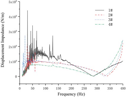
To obtain the parameter of impedance of foundation , hammering method was used to test using the same device. Transducer position when testing was shown in Fig. 8. Tested results after post-processing were shown in the Fig. 9.
Fig. 8Transducer position when testing
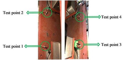
Fig. 9ZF tested by hammering method
4. Finite element model
To compare the isolation effectiveness of two-stage mounting system having integral intermediate mass with distributed intermediate mass. FEMs of the two types of mounting system was designed based on the scale experimental prototype having distributed intermediate mass was set up through ABAQUS as is shown in Fig. 10 and Fig. 11. Q235 whose density 7800 kg/m3, elasticity modulus 200 GPa, Poisson’s ratio 0.3 was used as the material of foundation, intermediate mass and rack to install a vibration generator. The upper and lower isolators were simulated by spring with three dimensional stiffness and both ends of the spring were six degrees of freedom coupling constrained to the foundation, upper rack and intermediate mass with its actual contract area respectively. Data of isolators’ three dimensional stiffness was obtained through practical testing so that can be used as input parameters. The foundation was six degrees of freedom coupling constrained to the ground.
Fig. 10FEM of two-stage distributed mounting system
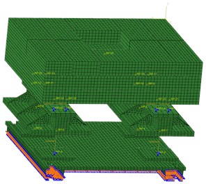
Fig. 11FEM of two-stage integral mounting system
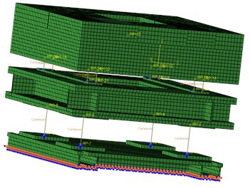
The frame structure intermediate mass equals on the left FEM equals to the distributed intermediate mass on the right FEM above. The impedance of foundation tested was used as the input parameter to predict vibration isolation effectiveness. Unit force at a specific frequency was exerted on the model to predict isolation effectiveness evaluated by vibration level difference calculated through force transmitting rate according to Eq. (15). Results were shown in Table 2:
where was the average force extracted from the up side of upper isolators and the average force extracted from the bottom side of lower isolators.
Table 2Isolation effectiveness of two types of mounting system predicted through FEM. Reference force: 1 N
Frequency (Hz) | Two-stage mounting system having integral intermediate mass (dB) | Two-stage mounting system having distributed intermediate mass (dB) |
40 | 41.0 | 43 |
55 | 48.7 | 49.5 |
80 | 58.2 | 59 |
120 | 55.1 | 56.3 |
5. Conclusions
In this paper, four-pole parameter method and numerical calculation method were used to analyse the two types of two-stage mounting systems and a scale prototype was designed to test isolation effectiveness of two-stage mounting system having distributed intermediate mass. Results showed:
1) Two-stage of mounting system having distributed intermediate mass can satisfy the criterion of practical projects in isolation efficiency over 40 dB which provide a new way for designer to choose when making mounting plan.
2) When the two types mounting systems having the same intermediate mass in quality, two-stage mounting system having distributed intermediate mass would obtain better isolation efficiency.
The usual frame designs, however, incorporate extended structural members which exhibit modal behaviour at acoustic frequency; thus, such frames do not act as rigid masses at these frequencies and the advantages of a two-stage mounting system are lost. In many such installations it is likely that better high-frequency isolation, plus perhaps a saving in weight, may be obtained essentially by replacing the frame with distributed compact mass which will act as rigid mass at high frequency like the two-stage mounting system having distributed intermediate mass I discussed in the paper.
Further research on how the vibration isolation effectiveness fluctuate with increasing intermediate compact mass and detailed physical explanation on why would distributed intermediate mass provide as well vibration isolation effectiveness as a frame structure intermediate masa work will be continued.
References
-
Den Hartog J. P. Mechanical Vibration. 3rdEdition, Mc-Graw Hill, 1948.
-
He Lin, Xu Wei Naval vessel machinery mounting technology and its recent advances. Acta Acustica, Vol. 38, Issue 2, 2013, p. 128-136.
-
Zhao Jianxue, Yu Xiang, Chai Kai, et al. Vibration isolation performance analysis of double layer vibration isolation system. Chinese Journal of Ship Research, Vol. 12, Issue 6, 2017, p. 101-107.
-
Snowdon J. C. Mechanical four-pole parameters and their application, Journal of Sound and Vibration, Vol. 15, Issue 3, 1971, p. 307-323.
-
Gorman R. M. Design and advantages of two-stage mounting system for major machine in ship’s engine room. Shock and Vibration Bulletin, Vol. 35, 1966, p. 227-234.
-
Mcgoldrick R. T. Calculation of Natural Frequencies and Normal Modes of Vibration for a Compound Isolation Mounting System. David Taylor Model Basin Report 1420, 1960.
-
Harbour J. P. Evaluation and Comparison of Electric Propulsion Motors for Submarines. Massachusetts Institute of Technology, Massachusetts, 2001.
-
Winberg M., Hansen C., Claesson I., et al. Active Control of Engine Vibrations in a Collins Class Submarine. Blekinge Institute of Technology, Australia, 2003.
-
Rivin E. Passive Vibration Isolation. The American Society of Mechanical Engineer, New York, 2003.
-
Jin W. H., Chung J. T. Vibration analysis of a flexible rotating disk with angular misalignment. Journal of Sound and Vibration, Vol. 274, 2004, p. 821-841.
-
Swinbanks M. A., Daley S. Advanced Submarine Technology - Project M Control Experiments and Simulations. Office on Naval Research, America, 1994.
-
Ma Y. T., Zhou Y. Summary of floating raft system. Ship Science and Technology, Vol. 30, Issue 4, 2008, p. 22-27.
-
Xu W., He L., Shi L. A Study on alignment disturbance control of air-suspended main engine. Journal of Vibration and Shock, Vol. 30, Issue 1, 2011, p. 6-10.
-
Widdle R. D., Krousgrill C. M., Sudhoff S. D. An induction motor model for high-frequency torsional vibration analysis. Journal of Sound and Vibration, Vol. 290, 2006, p. 865-881.
-
Fahy F., Gardonio P. Sound and structural Vibration. 2nd Edition, Academic Press, Amsterdam, 2007.
About this article

