Abstract
Truss bridges are integral part of the transport network, mainly railroads and partially road bridges. The investigated bridge is located in the western part of Slovakia, and it crosses the Vah River. Density of traffic on the bridge is not so high, so the bridge is accessible for repeating dynamic measurements. Many load situations were simulated. Among of them also a case, where one diagonal member was excited by an electromagnetic exciter during the measurements and the influence on other diagonals have been also analyzed. Results of dynamic measurements are shown in this paper in comparison to analytical solution and to FEM calculations.
Highlights
- Artificial excitation of one diagonal member can excite another diagonal member to the resonant frequency
- The FEM model prepared by using mainly BEAM elements can be used for comparison of global mode-shapes
- On the other hand, neglecting structural details can lead to a mismatch of experimentally obtained and calculated natural frequency
1. Introduction
Bridge structures represent an important part of the transport network. Generally, closures of bridges due to bad technical conditions can cause negative economic consequences. Because of that, preparing a reliable method as a practical tool for assessment of the conditions of existing bridges has become a very important research field [1, 2]. Nowadays, many research teams are working on a non-destructive testing (NDT) of truss bridges in their works [3-6]. There are several available methods how to monitor structures or to check operational conditions of bridge structures. The NDT methods can be based on vibrations [7], other types of waves [8] or radiation. Vibration based NDT methods belong to more used methods and one of them is based on natural frequency. It is the simplest method when the only natural frequency is investigated. The method was reviewed in [9]. Besides that, possible change in natural frequency can lead to identification of structural damage (Level 1 [10]).
Fig. 1Truss bridge – a view
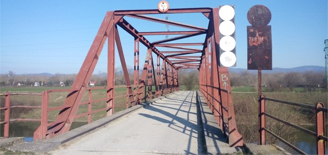
This work follows the laboratory experiment published by the authors [11] but a real structure was measured in this case. It connects the two sides of the Vah River canal, and it is described in [12] in more detail. In this study, diagonal members of the bridge (Fig. 1) have been monitored. Artificial electromagnetic exciters [13] were used for an excitation of the investigated structure.
The paper consists of the following sections. Section 2 deals with a Finite Element Method (FEM) model and numerical calculations; Section 3 describes the dynamic tests of chosen diagonal members; Section 4 is devoted to the analysis of results and Section 5 consists of some conclusions from the research.
2. FEM model and numerical calculations
Before the dynamic measurements, the initial FEM model was created. The FEM model consisted mainly of BEAM elements, but the bridge deck is modelled as SHELL elements. Then, numerical modal analysis was done. Some global results from the numerical calculation and the measurement are published in [12]. Besides that, local mode-shapes can be identified from the calculation. The first tensioned diagonal members are described in the next part of the paper, and their mode-shapes are shown in Fig. 2. Globally, Fig. 2(a) represents the 18th mode-shape and Fig. 2(b) represents the 19th mode-shape.
Fig. 2FEM of the truss bridge with local mode-shapes of the diagonal members (the 1st tensioned)
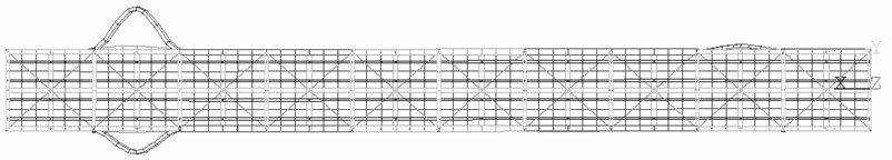
a)
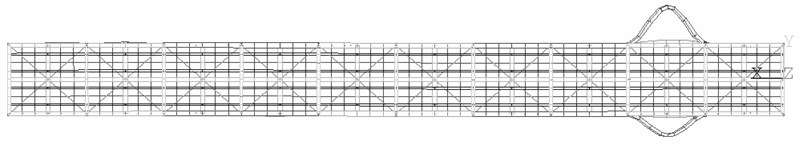
b)
Besides that, the natural frequency of the diagonal member has been calculated analytically. It has been considered that the member (Fig. 4) is represented by a continuous system [14]. In accordance with that, boundary conditions have been variously considered, as a simple supported beam (Case A) and full constraints on the both sides (Case B). Then, natural frequencies have been calculated for both cases. The results from the FEM calculations and the analytical solution are mentioned in the 4th section.
Fig. 3The 1st tensioned diagonal members: a) cross-section, b) side-view

a)
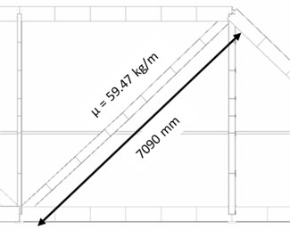
b)
3. Experimental tests
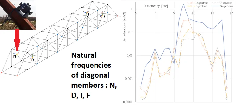
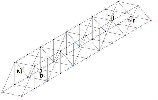
A NI cRIO 9074 device with one delta-sigma converter NI 9234 module was used for dynamic measurements. Four PCB Piezotronics 393B31 accelerometers were connected to the module. This combination represents the possibility to measure frequencies above the value of 0.5 Hz with amplitudes between the limits ± 4.9 ms-2. It was suitable for measurements of natural frequencies of truss members. Accelerometers (labelled in Fig. 4 as D, F, I, N) were placed at four points in the middle of the first tensioned diagonal members. Besides that, one of these diagonal members was excited by the electromagnetic harmonic exciter with 0.6 kg of moving mass (at the place of the accelerometer “N). The mass of the exciter (18 kg) was added in numerical analysis.
Fig. 4Placement of accelerometers (of the investigated diagonal members)
The excitation frequency has been changed smoothly. The frequencies from 5 Hz up to 15 Hz with 0.5 Hz step has been used. The used logging data rate was 2048 samples per second. After that, data were down-sampled to sampling rate 100 samples per second in the NI DIAdem software. Fast Fourier Transform (FFT) [15] has been also done in the NI DIAdem.
4. Analysis of results
The results of FFT for each member are shown in Fig. 5. The logarithmic scale was chosen for the -axis (Accelerations) in order to make the graph more readable.
Fig. 5Response spectrum of the 1st tensioned diagonal members (at places D, F, I, N)
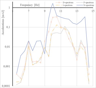
It can be seen from Fig. 5 that every single diagonal member has a bit different natural frequency. The lowest frequency has been obtained for the diagonal member with the accelerometer “N” where the exciter was attached. It represents more mass which vibrated on the diagonal member.
The following table (Table 1) compares the natural frequencies obtained by various methods. The results show that the difference is presented between FEM calculation and the experimentally obtained data. It can be caused that the FEM model neglect the real structural joints, so the model does not consider real boundary conditions.
Table 1The comparison of natural frequencies
Experimental measurement [Hz] | FEM calculation [Hz] | Analytical solution Case A [Hz] | Analytical solution Case B [Hz] |
10.5 up to 11.5 | 13.8 up to 14.2 | 6.5 | 14.6 |
5. Conclusions
It can be concluded from the presented results:
1) Artificial excitation of one diagonal member can excite another diagonal member to the resonant frequency.
2) The FEM model prepared by using mainly BEAM elements can be used for comparison of global mode-shapes, e.g., the comparison in [10]. On the other hand, neglecting structural details can lead to a mismatch of experimentally obtained and calculated natural frequency in this comparison.
3) Analytical solution shows that the real frequency of the diagonal member is between the result of the Case A (simple supported beam) and the Case B (fully constraint beam).
The various experimentally obtained frequencies can also indicate small inaccuracies between investigated diagonal members. If the FEM model includes modeling of structural details, it can be used for damage scenario simulations in the future. The presented method should be tested repeatedly to become a reliable method as a part of the evaluation system of bridge conditions.
References
-
Limongelli M. P., Chatzi E., Anžlin A. Condition assessment of roadway bridges: from performance parameters to performance goals. The Baltic Journal of Road and Bridge Engineering, Vol. 13, Issue 4, 2018, p. 345-356.
-
Caglayan O., Ozakgul K., Tezer O. Assessment of existing steel railway bridges. Journal of Constructional Steel Research, Vol. 69, Issue 1, 2012, p. 54-63.
-
Costa J. A. B., Figueiras J. A. Rehabilitation and condition assessment of a centenary steel truss bridge. Journal of Constructional Steel Research, Vol. 89, 2013, p. 185-197.
-
Yoshioka T., et al. Damage assessment of truss diagonal members based on frequency changes in local higher modes. Procedia Engineering, Vol. 14, 2011, p. 3119-3126.
-
Shibeshi R. D., Roth C. P. Field measurement and dynamic analysis of a steel truss railway bridge. South African Institution of Civil Engineering, Vol. 58, Issue 3, 2016, p. 28-36.
-
Bayraktar A., Altunisik A. C., Turker T. Structural health assessment and restoration procedure of an old riveted steel arch bridge. Soil Dynamics and Earthquake Engineering, Vol. 83, 2016, p. 148-161.
-
Čech J., et al. Structural condition assessment of the bridge in Ostrava. MATEC Web of Conferences, 2017.
-
Favai P., et al. Bridgemon: Improved Monitoring Techniques for Bridges. Civil Engineering Research in Ireland Belfast, UK, 2014, p. 179-184.
-
Salawu O. S. Detection of structural damage through changes in frequency: a review. Engineering Structures, Vol. 19, Issue 9, 1997, p. 718-723.
-
Comisu C.-C., Taranu N., Boaca G., Scutaru M.-C. Structural health monitoring system of bridges. Procedia Engineering, Vol. 199, Issue 2017, 2017, p. 2054-2059.
-
Venglar M., Sokol M., Ároch R. System identification of a truss beam. 22nd International Conference on Engineering Mechanics, 2016, p. 573-576.
-
Venglar M., Sokol M., Ároch R. Ambient vibration measurements of steel truss bridges. Journal of Measurements in Engineering, Vol. 6, Issue 4, 2018, p. 234-239.
-
Thorby D. Structural Dynamics and Vibration in Practice: an Engineering Handbook. Butterworth-Heinemann, Amsterdam, 2008.
-
Clough R., Penzien J. Dynamics of Structures. McGraw-Hill, New York, 2004.
-
Bendat Piersol J. A. Random Data. Wiley, Hoboken, 2010.
About this article

This paper was supported by the Slovak Research and Development Agency (SRDA), i.e. a grant from research program No. APVV-0236-12. It was also supported by VEGA No. 1/0749/19.
